Transcription
ixPREFACE11-11-21-31-41-51-61-71-81-921BINARY SYSTEMSDigital Computers and Digital SystemsBinary Numbers4Number Base Conversions6Octal and Hexadecimal Numbers9Complements10Signed Binary Numbers14Binary Codes17Binary Storage and Registers25Binary Logic28References32Problems33136BOOLEAN ALGEBRA AND LOGIC GATES2-12-22-3Basic Definitions36Axiomatic Definition of Boolean Algebra38Basic Theorems and Properties of Boolean Algebra41III
ivContents2-42-52-62-72-8349SIMPLIFICATION OF BOOLEAN oolean Functions45Canonical and Standard FOnTISOther Logic Operations56Digital Logic Gates58Integrated Circuits62References69Problems69The Map Method72Two- and Three-Variable Maps73Four-Variable Map78Five-Variable Map82Product of Sums Simplification84NAND and NOR Implementation88Other Two-Level Implementations94Don't-Care Conditions98The Tabulation Method101Determination of Prime Implicants101Selection of Prime Implicants106Concluding Remarks108References110ProblemsIIICOMBINATIONAL gn Procedure115Adders116121Subtractors124Code ConversionAnalysis Procedure126Multilevel NAND Circuits130Multilevel NOR Circuits138114
Contents4-95152Introduction152Binary Adder and Subtractor154Decimal Adder160Magnitude Comparator163166Decoders and EncodersMultiplexers173Read-Only Memory (ROM)180187Programmable Logic Array (PLA)192Programmable Array Logic (PAL)197ReferencesProblems197202SYNCHRONOUS SEOUENTIAL LOGIC6-16-26-36-46-56-66-76-87142MSI AND PLD COMPONENTS5-15-25-35-45-55-65-75-85-96Exclusive-OR p-Hops204210Triggering of Hip-FlopsAnalysis of Clocked Sequential CircuitsState Reduction and Assignment228Hip-Flop Excitation Tables231Design Procedure236Design of Counters247References251Problems251218REGISTERS, COUNTERS, AND THE MEMORY UNIT7-17-2VIntroduction257Registers258257
viContents7-37-47-57-67-77-87-9Shift Registers264Ripple Counters272Synchronous Counters277Timing Sequences285Random-Access Memory (RAM)Memory Decoding293299Error-Correcting CodesReferencesProblems8302303ALGORITHMIC STATE MACHINES IASMI8-18-28-38-48-58-69289307Introduction307ASM Chart309Timing Considerations312Control Implementation317Design with Multiplexers323PLA Control330References336Problems337ASYNCHRONOUS SEQUENTIAL is Procedure343Circuits with Latches352Design Procedure359Reduction of State and Flow TablesRace-Free State Assignment374Hazards379Design Example385References391Problems392341366
Contents10DIGITAL INTEGRATED ntroduction399Special Characteristics401Bipolar-Transistor Characteristics406RTL and DTL Circuits409412Transistor-Transistor Logic (TTL)Emmitter-Coupled Logic (ECL)422Metal-Oxide Semiconductor (MOS)424Complementary MOS (CMOS)427CMOS Transmission Gate Circuits430References433Problems434LABORATORY 36Introduction to Experiments436Binary and Decimal Numbers441Digital Logic Gates444Simplification of Boolean Functions446447Combinational CircuitsCode Converters449Design with Multiplexers451Adders and Subtractors452Flip-Flops455Sequential Circuits458Counters459Shift Registers461Serial Addition464Memory Unit465Lamp Handball467Clock-Pulse Generator471Parallel Adder473Binary Multiplier475Asynchronous Sequential Circuits477)
viii12ContentsSTANDARD GRAPHIC -Shape Symbols479Qualifying Symbols482Dependency Notation484Symbols for Combinational ElementsSymbols for Flip-Flops489Symbols for Registers491Symbols for Counters494Symbol for RAM496References497Problems497479486APPENDIX: ANSWERS TO SELECTED PROBLEMSINDEX499512
\Digital Design is concerned with the design of digital electronic circuits. The subjectis also known by other names such as logic design, digital logic, switching circuits, anddigital systems. Digital circuits are employed in the design of systems such as digitalcomputers, control systems, data communications, and many other applications that require electronic digital hardware. This book presents the basic tools for the design ofdigital circuits and provides methods and procedures suitable for a variety of digital design applications.Many features of the second edition remain the same as those of the first edition.The material is still organized in the same manner. The first five chapters cover combinational circuits. The next three chapters deal with synchronous clocked sequential circuits. Asynchronous sequential circuits are introduced next. The last three chaptersdeal with various aspects of commercially available integrated circuits.The second edition, however, offers several improvements over the first edition.Many sections have been rewritten to clarify the presentation. Chapters I through 7and Chapter 10 have been revised by adding new up-to-date material and deleting obsolete subjects. New problems have been formulated for the first seven chapters. Thesereplace the problem set from the first edition. Three new experiments have been addedin Chapter II. Chapter 12, a new chapter, presents the IEEE standard graphic symbolsfor logic elements.The following is a brief description of the subjects that are covered in each chapterwith an emphasis on the revisions that were made in the second edition.Ixf
XPrefaceChapter 1 presents the various binary systems suitable for representing informationin digital systems. The binary number system is explained and binary codes are illustrated. A new section has been added on signed binary numbers.Chapter 2 introduces the basic postulates of Boolean algebra and shows the correlation between Boolean expressions and their corresponding logic diagrams. All possiblelogic operations for two variables are investigated and from that, the most useful logicgates used in the design of digital systems are determined. The characteristics of integrated circuit gates are mentioned in this chapter but a more detailed analysis of theelectronic circuits of the gates is done in Chapter 11.Chapter 3 covers the map and tabulation methods for simplifying Boolean expressions. The map method is also used to simplify digital circuits constructed with ANDOR, NAND, or NOR gates. All other possible two-level gate circuits are consideredand their method of implementation is summarized in tabular form for easy reference.Chapter 4 outlines the formal procedures for the analysis and design of combinational circuits. Some basic components used in the design of digital systems, such asadders and code converters, are introduced as design examples. The sections on multilevel NAND and NOR implementation have been revised to show a simpler procedurefor converting AND-OR diagrams to NAND or NOR diagrams.Chapter 5 presents various medium scale integration (MS!) circuits and programmable logic device (PLD) components. Frequently used digital logic functionssuch as parallel adders and sub tractors, decoders, encoders, and multiplexers, are explained, and their use in the design of combinational circuits is illustrated with examples. In addition to the programmable read only memory (PROM) and programmablelogic array (PLA) the book now shows the internal construction of the programmablearray logic (PAL). These three PLD components are extensively used in the design andimplementation of complex digital circuits.Chapter 6 outlines the formal procedures for the analysis and design of clocked synchronous sequential circuits. The gate structure of several types of flip-flops is presented together with a discussion on the difference between pulse level and pulse transition triggering. Specific examples are used to show the derivation of the state tableand state diagram when analyzing a sequential circuit. A number of design examplesare presented with added emphasis on sequential circuits that use D-type flip-flops.Chapter 7 presents various sequential digital components such as registers, shiftregisters, and counters. These digital components are the basic building blocks fromwhich more complex digital systems are constructed. The sections on the random access memory (RAM) have been completely revised and a new section deals with theHamming error correcting code.Chapter 8 presents the algorithmic state machine (ASM) method of digital design.The ASM chart is a special flow chart suitable for describing both sequential and parallel operations with digital hardware. A number of design examples demonstrate the useof the ASM chart in the design of state machines.Chapter 9 presents formal procedures for the analysis and design of asynchronoussequential circuits. Methods are outlined to show how an asynchronous sequential cir-
\Prefacexlcuit can be implemented as a combinational circuit with feedback. An alternate implementation is also described that uses SR latches as the storage elements in an asynchronous sequential circuit.Chapter 10 presents the most common integrated circuit digital logic families. Theelectronic circuits of the common gate in each faruily is analyzed using electrical circuittheory. A basic knowledge of electronic circuits is necessary to fully understand thematerial in this chapter. Two new sections are induded in the second edition. One section shows how to evaluate the numerical values of four electrical characteristics of agate. The other section introduces the CMOS transmission gate and gives a few examples of its usefulness in the construction of digital circuits.Chapter 11 outlines 18 experiments that can be performed in the laboratory withhardware that is readily and inexpensively available commercially. These experimentsuse standard integrated circuits of the TTL type. The operation of the integrated circuits is explained by referring to diagrams in previous chapters where siruilar components are originally introduced. Each experiment is presented informally rather than ina step-by-step fashion so that the student is expected to produce the details of the circuit diagram and formulate a procedure for checking the operation of the circuit in thelaboratory.Chapter 12 presents the standard graphic symbols for logic functions recommendedby ANSI/IEEE standard 91-1984. These graphic symbols have been developed for SSIand MSI components so that the user can recognize each function from the uniquegraphic symbol assigned to it. The best time to learn the standard symbols is whilelearning about digital systems. Chapter 12 shows the standard graphic symbols of allthe integrated circuits used in the laboratory experiments of Chapter 11.The various digital componets that are represented throughout the book are similarto commercial MSI circuits. However. the text does not mention specific integrated circuits except in Chapters 11 and 12. The practical application of digital design will beenhanced by doing the suggested experiments in Chapter 11 while studying the theorypresented in the text.Each chapter in the book has a list of references and a set of problems. Answers tomost of the problems appear in the Appendix to aid the student and to help the independent reader. A solutions manual is available for the instructor from the publisher.M. Morris Mano
Binary' ystems1·1DIGITAL COMPUTERS AND DIGITAL SYSTEMSDigital computers have made possible many scientific, industrial, and commercial advances that would have been unattainable otherwise. Our space program would havebeen impossible without real-time, continuous computer monitoring, and many business enterprises function efficiently only with the aid of automatic data processing.Computers are used in scientific calculations, commercial and business data processing,air traffic control, space guidance, the educational field, and many other areas. Themost striking property of a digital computer is its generality. It can follow a sequenceof instructions, called a program, that operates on given data. The user can specify andchange programs and/or data according to the specific need. As a result of thisflexibility, general-purpose digital computers can perform a wide variety of information-processing tasks.The general-purpose digital computer is the best-known example of a digital system.Other examples include telephone switching exchanges, digital voltmeters, digitalcounters, electronic calculators, and digital displays. Characteristic of a digitaLsYstemis its manipulation. of discrete elements of information: SlicIi(JJscreteeiemenis may be .electric impulses, th;;-decimaf iigTiS:-tlie letters of an alphabet, arithmetic operations,punctuation marks, or any other set of meaningful symbols. The juxtaposition of discrete elements of information represents a quantity of information. For example, theletters d, 0, and g form the word dog. The digits 237 form a number. Thus, a sequenceof discrete elements forms a language, that is, a discipline that conveys information.Early digital computers were used mostly for numerical computations. In this case, the1
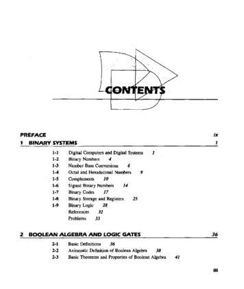
2Chapter 1Binary Systemsdiscrete elements used are the digits. From this application, the term digital computerhas emerged. A more appropriate name for a digital computer would be a "discrete information-processing system."Discrete elements of information are represented in a digital system by physicalquantities called signals. Electrical signals such as voltages and currents are the mostcommon. The signals in all present-day electronic digital systems have only two discrete values and are said to be binary. The digital-system designer is restricted to theuse of binary signals because of the lower reliability of many-valued electronic circuits.In other words, a circuit with ten states, using one discrete voltage value for each state,can be designed, but it would possess a very low reliability of operation. In contrast, atransistor circuit that is either on or off has two possible signal values and can be constructed to be extremely reliable. Because of this physical restriction of components,and because human logic tends to be binary, digital systems that are constrained to takediscrete values are further constrained to take binary values.Discrete quantities of information arise either from the nature of the process or maybe quantized from a continuous process. For example, a payroll schedule is an inherently discrete process that contains employee names, social security numbers, weeklysalaries, income taxes, etc. An employee's paycheck is processed using discrete datavalues such as letters of the alphabet (names), digits (salary), and special symbols suchas . On the other hand, a research scientist may observe a continuous process butrecord only specific quantities in tabular form. The scientist is thus quantizing his continuous data. Each number in his table is a discrete element of information.Many physical systems can be described mathematically by differential equationswhose solutions as a function of time give the complete mathematical behavior of theprocess. An analog computer performs a direct simulation of a physical system. Eachsection of the computer is the analog of some particular portion of the process understudy. The variables in the analog computer are represented by continuous signals, usually electric voltages that vary with time. The signal variables are considered analogousto those of the process and behave in the same manner. Thus, measurements of theanalog voltage can be substituted for variables of the process: The term analog signal issometimes substituted for continuous signal because "analog computer" has come tomean a computer that manipulates continuous variables.To simulate a physical process in a digital computer, the quantities must be quantized. When the variables of the process are presented by real-time continuous signals,the latter are quantized by an analog-to-digital conversion device. A physical systemwhose behavior is described by mathematical equations is simulated in a digital computer by means of numerical methods. When the problem to be processed is inherentlydiscrete, as in commercial applications, the digital computer manipulates the variablesin their natural form.A block diagram of the digital computer is shown in Fig. 1-1. The memory unitstores programs as well as input, output, and intermediate data. The processor unit performs arithmetic and other data-processing tasks as specified by a program. The con-trol unit supervises the flow of information between the various units. The control unitretrieves the instructions, one by one, from the program that is stored in memory. For
Section 1 1 Digital Computers and Digital Systems3Processor,Controlunitorarithmetic unitStorage,ormemory unitInputdevicesand controlOutputdevicesand controlFIGURE 1·1Block diagram of a digital computereach instruction, the control unit informs the processor to execute the operationspecified by the instruction. Both program and data are stored in memory. The controlunit supervises the program instructions, and the processor manipulates the data asspecified by the program.The program and data prepared by the user are transferred into the memory unit bymeans of an input device such as a keyboard. An output device, such as a printer, receives the result of the computations and the printed results are presented to the user.The input and output devices are special digital systems driven by electromechanicalparts and controlled by electronic digital circuits.An electronic calculator is a digital system similar to a digital computer, with the input device being a keyboard and the output device a numerical display. Instructions areentered in the calculator by means of the function keys, such as plus and minus. Dataare entered through the numeric keys. Results are displayed directly in numeric form.Some calculators come close to resembling a digital computer by having printing capabilities and programmable facilities. A digital computer, however, is a more powerfuldevice than a calculator. A digital compiIter can accommodate many other input andoutput devices; it can perform not only arithmetic computations, but logical operationsas well and can be programmed to make decisions based on internal and external conditions.A digital computer is an interconnection of digital modules. To understand the operation of each digital module, it is necessary to have a basic knowledge of digital systems and their general behavior. The first four chapters of the book introduce the basictools of digital design such as binary numbers and codes, Boolean algebra, and the basic building blocks from which electronic digital circuits are constructed. Chapters 5and 7 present the basic components found in the processor unit of a digital computer.
4Chapter 1Binary SystemsThe operational characteristics of the memory unit are explained at the end of Chapter7. The design of the control unit is discussed in Chapter 8 using the basic principles ofsequential circuits from Chapter 6.It has already been mentioned that a digital computer manipulates discrete elementsof information and that these elements are represented in the binary form. Operandsused for calculations may be expressed in the binary number system. Other discrete elements, including the decimal digits, are represented in binary codes. Data processing iscarried out by means of binary logic elements using binary signals. Quantities arestored in binary storage elements. The purpose of this chapter is to introduce the various binary concepts as a frame of reference for further detailed study in the succeedingchapters.1-2BINARY NUMBERSA decimal number such as 7392 represents a quantity equal to 7 thousands plus 3 hundreds, plus 9 tens, plus 2 units. The thousands, hundreds, etc. are powers of 10 impliedby the position of the coefficients. To be more exact, 7392 should be written as7X10 3 3X10² 9X10' 2 x 10 However, the convention is to write only the coefficients and from their position deduce the necessary powers of 10. In general, a number with a decimal point is represented by a series of coefficients as follows:The aj coefficients are one of the ten digits (0, 1,2, . ,9), and the subscript valuejgives the place value and, hence, the power of 10 by which the coefficient must be multiplied.10'a, 104a4 103a3 102a2 lOla, 100ao 1O-'a , 1O- 2a 2 1O- 3a 3The decimal number system is said to be of base, or radix, 10 because it uses ten digitsand the coefficients are multiplied by powers of 10. The binary system is a differentnumber system. The coefficients of the binary numbers system have two possible values: 0 and 1. Each coefficient aj is multiplied by 21. For example, the decimal equivalent of the binary number 11010.11 is 26.75, as shown from the multiplication of thecoefficients by powers of 2:I X 24 I X 2 3 0 X 22 1 X 2' 0 x 2 I x 2 -, 1 X 2- 2 26.75In general, a number expressed in base-r system has coefficients multiplied by powersof r:an'r" a,, 1'r,,--'1 ' , ' a2'r 2 aj'r Go G J,,--l a 2'r- 2 ' , . a m'r- m
Section 1-25Binary NumbersThe coefficientsaj rangein vllJue Jrom 0 to r - 1. To distinguish between numbers ofdifferent bases, we enclose the coefficients in parentheses and write a subscript equal tothe base used (except sometimes for decimal numbers, where the content makes it obvious that it is decimal). An example of a base-5 number is(4021.2)5 4X53 0X5' 2X5' 1X50 2X5-' (511.4hoNote that coefficient values for base 5 can be only 0, I, 2, 3, and 4.It is customary to borrow the needed r digits for the coefficients from the decimalsystem when the base of the number is less than 10. The letters of the alphabet are usedto supplement the ten decimal digits when the base of the number is greater than 10.For example, in the hexadecimal (base 16) number system, the first ten digits are borrowed from the decimal system. The letters A, B, C, D, E, and F are used for digits10, 11, 12, 13, 14, and 15, respectively. An example of a hexadecimal number is(B 65Fh. 11 X 163 6 X 16' 5 X 16 15 (46687)10The first 16 numbers in the decimal, binary, octal, and hexadecimal systems are listedin Table I-I.TABLE ,-,Numbers with Different BasesDecimalBinary(base 10)(base 11OCtal(base e 16)I23456789ABCDEFArithmetic operations with numbers in base r follow the same rules as for decimalnumbers. When other than the familiar base 10 is used, one must be careful to use onlythe r allowable digits. Examples of addition, subtraction, and multiplication of two binary numbers are as follows:
6Chapter 1Binary Systemsaugend:addend:sum:101101 100111multiplicand:multiplier:1011x 101product:101100001011110111000110The sum of two binary numbers is calculated by the same rules as in decimal, exceptthat the digits of the sum in any significant position can be only 0 or I. Any carry obtained in a given significant position is used by the pair of digits one significant positionhigher. The subtraction is slightly more complicated. The rules are still the same as indecimal, except that the borrow in a given significant position adds 2 to a minuenddigit. (A borrow in the decimal system adds 10 to a minuend digit.) Multiplication isvery simple. The multiplier digits are always I or O. Therefore, the partial products areequal either to the multiplicand or to O.1-3NUMBER BASE CONVERSIONSA binary number can be converted to decimal by forming the sum of the powers of 2of those coefficients whose value is 1. For example(1010.011), 2' 21 2' 2- 1 (10.375)10The binary !lumber has four I's and the decimal equivalent is found from the sum offour powers of 2. Similarly, a number expressed in base r can be converted to its decimal equivalent by mUltiplying each coefficient with the corresponding power of randadding. The following is an example of octal-to-decimal conversion:(630.4h 6X82 3X8 4X8- 1 (408.5)10The conversion from decimal to binary or to any other base-r system is more convenient if the number is separated into an integer part and a fraction part and theconversion of each part done separately. The conversion of an integer from decimal tobinary is best explained by example.Example1-1Convert decimal 41 to binary. First, 41 is divided by 2 to give an integer quotient of 20and a remainder of 4. The quotient is again divided by 2 to give a new quotient andremainder. This process is continued until the integer quotient becomes O. The coefjicients of the desired binary number are obtained from the remainders as follows:
Section 1-3Integerquotient41220210RemainderNumber Base ConversionsCoefftclent20 I2ao 10 0a, 05 0a2 02 I2a, 2: I 0a4 0 0 I2as 12 52: 2I2answer: (41)107II (a,a4a,a2a,ao)' (101001),The arithmetic process can be manipulated more conveniently as follows:IntegerRemainder41201052I oThe conversion from decimal integers to any base-r system is similar to the example, except that division is done by r instead of 2.Example1-2Convert decimal 153 to octal. The required base r is 8. First, 153 is divided by 8 togive an integer quotient of 19 and a remainder of I. Then 19 is divided by 8 to give aninteger quotient of 2 and a remainder of 3. Finally, 2 is divided by 8 to give a quotientof 0 and a remainder of 2. This process can be conveniently manipulated as follows:153192oI32L (231).
8Chapter 1Binary SystemsThe conversion of a decimal fraction to binary is accomplished by a method similarto that used for integers. However, multiplication is used instead of division, and integers arc accumulated instead of remainders. Again, the method is best explained byexample.Example1-3Convert (0.6875)10 to binary. First, 0.6875 is multiplied by 2 to give an integer and afraction. The new fraction is multiplied by 2 to give a new integer and a new fraction.This process is continued until the fraction becomes 0 or until the number of digitshave sufficient accuracy. The coefficients of the binary number are obtained from theintegers as follows:Integer0.6875 x 2 0.3750 x 2 0.7500 X 2 0.5000 X 2 Answer: (0.6875)'0 (O.a10Fraction 0.37500.75000.50000.0000la-2u-3 a-4h Coefficienta-I 1U-2 0a-3 a-4 (O.lDII), To conyert a decimal fraction to a number expressed in base r, a similar procedure isused. Multiplication is by r instead of 2, and the coefficients found from the integersmay range in value from 0 to r - I instead of 0 and I.ExampleConvert (0.513)10 to octal.1-40.513 x 8 4.1040.104X8 0.8320.832 x 8 6.6560.656 x 8 5.2480.248 x 8 1.9840.984 x 8 7.872The answer, to seven significant figures, is obtained from the integer part of the products:(0.513),0 (0.406517 . ls The conversion of decimal numbers with both integer and fraction parts is done byconverting the integer and fraction separately and then combining the two answers. Using the results of Examples 1-1 and 1-3, we obtain
Section 1 4(41.6875)10Octal and Hexadecimal Numbers9 (101001.10I1hFrom Examples 1-2 and 1-4, we have(153.513)10 (231.406517),1-4OCTAl. AND HEXADECIMAl. NUMBERSThe conversion from and to binary, octal, and hexadecimal plays an important part indigital computers. Since 23 8 and 24 16, each octal digit corresponds to three binary digits and each hexadecimal digit corresponds to four binary digits. The conversion from binary to octal is easily accomplished by partitioning the binary number intogroups of three digits each, starting from the binary point and proceeding to the leftand to the right. The corresponding octal digit is then assigned to each group. The following example illustrates the -.JL-.JL-.J374000110 h (26153.7460),L-.JL-.J06Conversion from binary to hexadecimal is similar, except that the binary number is divided into groups of four l.-.JBF (2C6B.F2h.0010 hl.-.J2The corresponding hexadecimal (or octal) digit for each group of binary digits is easilyremembered after studying the values listed in Table 1-1.Conversion from octal or hexadecimal to binary is done by a procedure reverse tothe above. Each octal digit is converted to its three-digit binary equivalent. Similarly,each hexadecimal digit is converted to its four-digit binary equivalent. This is illustrated in the following examples:(673.124),(306.Dh. ( (110111011001010100 00110'---'61101l.-.JhDBinary numbers are difficult to work with because they require three or fourtimes as many digits as their decimal equivalent. For example, the binary number111111111111 is equivalent to decimal 4095. However, digital computers use binarynumbers and it is sometimes necessary for the human operator or user to communicatedirectly with the machine by means of binary numbers. One scheme that retains the binary system in the computer but reduces the number of digits the human must consider
10Chapter 1Binary Systemsutilizes the relationship between the binary number system and the octal or hexadecimal system. By this method, the human thinks in terms of octal or hexadecimal numbers and performs the required conversion by inspection when direct communicationwith the machine is necessary. Thus the binary number 111111111111 has 12 digitsand is expressed in octal as 7777 (four digits) or in hexadecimal as FFF (three digits).During communication between people (about binary numbers in the computer), theoctal or hexadecimal representation is more desirable because it can be expressed morecompactly with a third or a quarter of the number of digits required for the equivalentbinary number. When the human co
Digital Design is concerned with the design of digital electronic circuits. The subject is also known by other names such as logic design, digital logic, switching circuits, and digital systems. Digital circuits are employed in the design of systems such as digital computers, control syst