Transcription
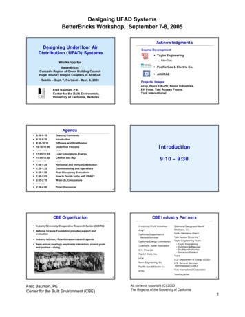
Designing UFAD SystemsBetterBricks Workshop, September 7-8, 2005AcknowledgmentsDesigning Underfloor AirDistribution (UFAD) SystemsCourse Development Taylor Engineering Workshop forAllan Daly Pacific Gas & Electric Co.BetterBricksCascadia Region of Green Building CouncilPuget Sound / Oregon Chapters of ASHRAE ASHRAESeattle – Sept. 7, Portland – Sept. 8, 2005Projects, ImagesArup, Flack Kurtz, Nailor Industries,EH Price, Tate Access Floors,York InternationalFred Bauman, P.E.Center for the Built Environment,University of California, Berkeley2Agenda 9:00-9:10Opening Comments 9:10-9:30Introduction 9:30-10:10Diffusers and Stratification 10:10-10:50 10:50 -11:05 11:05-11:45Load Calculations, Energy 11:45-12:00Comfort and IAQ 12:00 -1:00 1:00-1:20Horizontal and Vertical DistributionCommissioning and Operations 1:35-1:50Post-Occupancy Evaluations 1:50-2:05How to Decide to Go with UFAD? 2:15 -2:30 2:30-4:009:10 – 9:30Lunch 1:20-1:35 2:05-2:15IntroductionUnderfloor PlenumsBreakWrap-Up, ConclusionsBreakPanel Discussion3CBE OrganizationCBE Industry Partners Industry/University Cooperative Research Center (I/UCRC)Armstrong World Industries National Science Foundation provides support andevaluationArup* Industry Advisory Board shapes research agenda Semi-annual meetings emphasize interaction, shared goalsand problem solvingSkidmore Owings and MerrillSteelcase, Inc.California Department ofGeneral ServicesSyska Hennessy GroupCalifornia Energy CommissionTaylor Engineering Team:Charles M. Salter AssociatesE.H. Price Ltd.Flack Kurtz, Inc.HOKKeen Engineering, Inc.Pacific Gas & Electric Co.RTKLTate Access Floors Inc.* Taylor EngineeringGuttmann & BlaevoetSouthland IndustriesSwinerton BuildersTraneU.S. Department of Energy (DOE)*U.S. General ServicesAdministration (GSA)*York International Corporation*founding partner5Fred Bauman, PECenter for the Built Environment (CBE)6All contents copyright (C) 2000The Regents of the University of California1
Designing UFAD SystemsBetterBricks Workshop, September 7-8, 2005Overhead SystemUnderfloor air distribution system55 F-57 F61 F-65 F78Underfloor vs. ConventionalAir Distribution System Design IssuesPotential UFAD Benefits Underfloor air supply plenum Improved occupant comfort,productivity and health Air supplied into occupied zone near floor level Improved ventilation efficiencyand indoor air quality Higher supply air temperatures (for cooling) Reduced energy use Allows for occupant control Reduced life-cycle building costs Properly controlled stratification leads to reduced energyuse while maintaining comfort Improved flexibility forbuilding services Reduced space sensible heat load Perimeter zone solutions are critical Reduced floor-to-floor height innew construction Access floor improves flexibility and re-configurability910Room Air StratificationCurrent Barriers to UFAD Technology(cooling operation) Lack of familiarity by building industry Higher first costs Need for design guidelines and tools Fundamental research needed on key issues Room air stratification Underfloor plenums Energy performance Thermal comfort and ventilation effectiveness Problems with applicable standards and codes11Fred Bauman, PECenter for the Built Environment (CBE)12All contents copyright (C) 2000The Regents of the University of California2
Designing UFAD SystemsBetterBricks Workshop, September 7-8, 2005Floor ConstructionIntegrated Service Plenum1314Underfloor Air & PowerPLUG & PLAYPOWER andCONTROLSVAVDiffuserUnderfloor HVAC ConceptModularWiring1516ASHRAE Research Project RP-1064:UFAD Design GuideASHRAE UFAD Design GuideCONTENTS (243 pp.) Project start: September 19991. Primary author – Fred Bauman2. Contributing author – Allan Daly3. Sponsored by ASHRAE and CBE4. Technical oversight by TC 5.3,Room Air Distribution5.6. Guide published by ASHRAE inDecember 20037. Available from ASHRAE bookstore8. Developed ASHRAE ProfessionalDevelopment Seminar (PDS)Fred Bauman, PECenter for the Built Environment (CBE)IntroductionRoom Air DistributionThermal Comfort andIndoor Air QualityUnderfloor Air SupplyPlenumsUFAD EquipmentControls, Operation, andMaintenanceEnergy UseDesign, Construction, r and SpecialSystemsCost ConsiderationsStandards, Codes, andRatingsDesign MethodologyExamplesFuture DirectionsGlossaryReferences andAnnotated BibliographyIndex1718All contents copyright (C) 2000The Regents of the University of California3
Designing UFAD SystemsBetterBricks Workshop, September 7-8, 2005Development of UFAD Design GuideCurrent status of UFAD technology Strong interest due to several attractive features Design Guide material Research (laboratory, field, simulation) Design experience (literature, interviews, case studies) Manufacturer’s literature Current database of UFAD projects in North America 300 installations 50-55 million ft2 Includes UFAD and closely related task/ambient conditioning(TAC) systemsRoutinely considered as HVAC design option Ongoing research and experience in the field are generatingnew and improved informationCovers topics in which important differences exist betweenUFAD and conventional overhead design Problems found in completed UFAD installations are often thesame as those found in overhead buildingsIdentifies areas where more work is needed Conservative design Poor construction practice Inadequate commissioning, controls, and operation19Raised floor and UFAD adoption¾ 2002: 7% of new officesused raised floors,15% of these with UFADsystems.¾ 2004: 14% -15% haveraised floors, 45% ofthese with UFADsystems.How Many UFAD Projects are Installed? Through 2000, approximately 80 projectsrepresenting some 20 million sq ft in US.20%% of New Office Construction¾ 1995: Less than 3% ofnew office buildings hadraised floors, UFAD a“fringe” element16%Raised Floor Between 2000-2002, the number of new projectsrepresented another 25 million sq ft.UFAD12% CBE currently maintains database of NorthAmerican UFAD projects with over 300installations representing 50-55 million sq ft.8%4%0%19952019971999200120032005Year The jobs are getting larger. The Bank One Centerin Chicago (1.5 million sq ft) was completed in2003 and several more projects over 1 million sq ftare now in design or under construction.2122Diffuser typesVariable area (VA)SwirlDiffusers and Stratification9:30 – 10:10Swirl, horizontal dischargeLinear bar grille24Fred Bauman, PECenter for the Built Environment (CBE)All contents copyright (C) 2000The Regents of the University of California4
Designing UFAD SystemsBetterBricks Workshop, September 7-8, 2005Personal control of swirl diffuserSwirl DiffusersRotate face plateSwirl floor diffuser25Personal control of swirl diffuser26Individual Plenum Box2728Office cubiclesToo many!One diffuser per workstation29Fred Bauman, PECenter for the Built Environment (CBE)30All contents copyright (C) 2000The Regents of the University of California5
Designing UFAD SystemsBetterBricks Workshop, September 7-8, iable Air Volume PerformanceBar Grilles in PerimeterCONSISTANT VELOCITY - VARIABLE VOLUMEMaintain constant discharge velocity even as air reduces3334Perimeter solution:Variable Speed Fan-Coil ControlUnderfloor variable-speed fan-coilMax Fan Speed130 FDischarge AirTemperatureSetpointDesignFan SpeedAirflowGlazingReturn Air GrilleNo U/A diffusersin perimeter zones30% DesignFan SpeedTHeating CoilRaised Access FloorDesign AirflowAirflowFan SpeedReturn Air Plenum30% Design AirflowFan SpeedLowest PossibleFan Speed( 15% MaxFan Speed)Linear BarDiffuserMinimum Airflow(due topressurizedplenum)60 FFan Coil w/ ECM motorHeating Loop OutputDeadbandCooling Loop OutputFlex Duct35Fred Bauman, PECenter for the Built Environment (CBE)36All contents copyright (C) 2000The Regents of the University of California6
Designing UFAD SystemsBetterBricks Workshop, September 7-8, 2005Perimeter solution:Underfloor variable-speed fan-coil3738Perimeter solution – variable-area diffuserPerimeter solution – variable-area diffuserCooling modeHeating mode3940Task/Ambient Conditioning SystemsDiffuser Code Compliance Desktop control for maximumoccupant comfort control In the past, technically only all-metal diffusers could meet all codeflame spread and smoke ratings Relatively rare in practice For plastic diffusers: UL 94 (Flammability of Plastic Devices) NFPA 90A (smoke developed index 50) Smoke test protocol is NFPA 255 (burn 25 ft sample) NFPA 90A exception (smoke optical density) NFPA 262 or UL 2043 (new test for smoke generation from plastic diffusersin 2002 edition of NFPA 90A)41Fred Bauman, PECenter for the Built Environment (CBE)42All contents copyright (C) 2000The Regents of the University of California7
Designing UFAD SystemsBetterBricks Workshop, September 7-8, 2005Room air stratificationOverhead Air Distribution System(cooling operation)Mixing system tries to maintain uniform temperatureand ventilation conditions throughout space4344Displacement Ventilation SystemUnderfloor Air Distribution SystemMinimize mixing in occupied zoneStratification height (SH) separates upper and lower zonesIncreased mixing up to throw height (TH)Diffuser throw below stratification height (SH)45Underfloor Air Distribution System46Air PatternsdisplacementswirlDiffuser throw above stratification level (SH)47Fred Bauman, PECenter for the Built Environment (CBE)48All contents copyright (C) 2000The Regents of the University of California8
Designing UFAD SystemsBetterBricks Workshop, September 7-8, 2005Diffuser ComparisonRoom Air Stratification TestingApproachDischargeSettingModel Full-scale laboratory tests of commercially available floordiffusers in realistic office setting. Study impact of various design and operating parameterson room air stratification (RAS).Vertical ThrowtoClear Zone50 VerticalVertical100754-62.5 - 4.51.51.5 Proper designVariableAreaVerticalFull Spread150110852.04.5 System sizing Energy efficient operationBarVerticalVertical75 / ft40 / ft2518- Thermal comfort Indoor air quality Control of stratification is crucial to:49Stratification test resultsResults – Interior office, swirl diffusersEffect of airflow rate: constant load, swirl diffusers, interior zoneASHRAE Std.55-2004 RAS profiles for high room load, 6 workstations5 F T115010Normalized to 65 F SAT and common deltaT879Swirldiffusers86756Height, ftHeight, ft101.0 cfm/sq. ft0.6 cfm/sq. ft0.3 cfm/sq. ft943Delta T 8 FDelta T 13 FLow roomtemperatureHigh roomtemperature54High throw, 2 diffusers32Still satisfies vertical temperaturedifference (5 F) with 40% less air1Low throw, 8 diffusersHigh throw, 2 diffusers2Low throw, 10 diffusersLowest throw, 7 DV diffusers10697071727374757677787980Room Temperature, F8182510656667686970717273747576777879Room Temperature, F52Stratification Test ResultsVariable Area vs. SwirlEffect of supply air temperature: constant load, swirl diffusers, interior zoneVA Diffuser11109Swirl DiffuserHeight, 879808182Room Temperature, FSource: ASHRAEJournal May 2002T estV A -1V A -2V A -3S W -1S W -2R oomL oadW / ft 22 .62 .91 .82 .52 .7R oomA i r f lo wc fm /ft20 .80 .80 .40 .60 .6D iffu s erf l o w r a te ,(% o fd e s ig n )70%30%40%90%40%50 fpmT h ro wft7 7 7 4 2Fred Bauman, PECenter for the Built Environment (CBE)5354All contents copyright (C) 2000The Regents of the University of California9
Designing UFAD SystemsBetterBricks Workshop, September 7-8, 2005RAS Testing ResultsRAS Testing Results(Perimeter zone cooling)(Cooling performance) The amount of stratification is primarily driven byroom airflow relative to load, and throw height. Key perimeter zone issuesStratification will increase as room airflow and/or diffuserthrow height are reduced for constant heat input.If too much air is delivered or throw height is too high,stratification will be reduced (approaching a well-mixedsystem), thereby compromising energy performance(increased fan energy, and lower RAT). Supply air temperature Diffuser throw height, airflow rate, amount of mixing Blinds up or blinds down Net effect is that cooling air quantities inperimeter zones can be in the range of 25% less to15% greater, depending on the amount ofstratification and other operating conditions.Optimized control strategies should promote stratification(reduce airflow requirements), while balancing this withcomfort considerations ( T 3-4 F in occupied zone).Due to stratification, consider increasing thermostat setpointby 1-2 F, especially in interior zones.55Stratification (in practice)Controlling Room Air Stratification GuidelinesMonitored Data from an Underfloor System80SensorLocations78 Perimeter Office1st floor, east perim10'8'6'4'2'0'767456 Promote stratification (reduce airflow requirements), whilemaintaining comfort: T 3-4 F in occupied zone.Don’t be too conservative! Airflow should be no greater thanOH systems.Provide controls to reduce airflow to interior (rather than raisesetpoint only) in case sizing is too conservative.72stratificationduring coolingmode70 Technology needsmixingduringheatingmode68noon6pmCooling airflow design tool Impact of stratification on thermal comfort Identify thermostat control strategiesWed 8/23Tue 8/226am66 5758Underfloor Air Supply PlenumsUnderfloor PlenumsRoom10:10 – 10:50Return Plenum60Fred Bauman, PECenter for the Built Environment (CBE)All contents copyright (C) 2000The Regents of the University of California10
Designing UFAD SystemsBetterBricks Workshop, September 7-8, 2005Plenum Design VariationsAirflow Performance Issues Pressurized plenum Objective – deliver desired amount of air Passive diffusers Pressurized vs. zero-pressure Most common approach and focus of current practice Reduced static pressure Plenum height (obstructions) Size of plenum zone Air leakage Plenum inlet conditions Zero-pressure plenum Active (fan-powered) diffusersNot as popular due to perceived higher costs Inlet velocity Fully ducted Inlet direction (open, vanes, plates)Not as popular due to high cost and lack of flexibility Location in zone Most designs are hybrid solutions Number of inlets in zone6162Underfloor Air Supply PlenumsResearch ResultsFull-Scale Plenum Test Facility Phase 1 – Airflow Performance ObjectiveInvestigate practical plenum configuration issues, includingminimum plenum height, for which acceptable airflowperformance can be achieved in pressurized underfloorplenums.4" x 14" Floor grills(typical)Plenum 23"x 23"DuctM 10'ApproachEmpirical experiments in full-scale underfloor air supplyplenum test facility.4' UnderfloorbarrierMMMMMMMMM40'80'Measurementpoint (typical)Obstruction #1Plan ViewRemovablefloor panels (2)Obstruction #224'19'14'10'Raised FloorConcrete SlabSection View63Plenum Schematic Cross-Section64Results Airflow delivery is very uniform from an 8-inchpressurized underfloor plenum over a full range ofsupply volumes (0.5-1.5 cfm/ft2), even at adistance of 80 feet from the plenum inlet.Plenum Schematic Cross-SectionFinish Floor Level1-inch Floor Panel Uniformity (less than 10% variation) is preservedfor solid obstructions with only 1.5 inches of clearspace.2"1"7"2"2"2"2"Polystyrene Blocks3"Concrete Slab65Fred Bauman, PECenter for the Built Environment (CBE)66All contents copyright (C) 2000The Regents of the University of California11
Designing UFAD SystemsBetterBricks Workshop, September 7-8, 2005Air Flow Ratio: 8-inch plenumPublication“How Low Can You Go?”Air Flow Performance ofLow-Height Underfloor Plenums130%1.5 cfm/sf1.0 cfm/sfDelivered Air Flow Ratio(Measured flow/Uniform flow)120%F. Bauman, P. Pecora, and T. WebsterCenter for the Built EnvironmentUniversity of CaliforniaBerkeley, California0.5 cfm/sf110%100%October 199990%PDF available from: 0607080Distance from Fan Inlet (ft)6768Smoke TestPlenum Air LeakageAir leakage between Floor Panels Air leakage from a pressurized plenum may impact energyuse and can impair system performance if not accountedfor.Air LeakageFloor DiffuserFloor Panel Types of leakage Leakage between floor panels Leakage due to poor sealing and construction69Air Leakage Test Setup70Carpet Tile ConfigurationsAlignedOffset71Fred Bauman, PECenter for the Built Environment (CBE)72All contents copyright (C) 2000The Regents of the University of California12
Designing UFAD SystemsBetterBricks Workshop, September 7-8, 2005Thermal Performance IssuesPressurized PlenumsAir Leakage between Floor PanelsCarpet Tile Configurations Objective – deliver air at the desired temperatureusing a minimum amount of energy1 2Air Leakage (cfm/ft )0.9Plenum inlet conditions Supply air temperature0.8Bare panels0.7 Inlet velocity and directionAligned carpet0.6Offset carpet0.5 Thermal decay Heat transfer coefficients (slab and panels)0.4 Velocity and residence time of air in plenum0.30.2 0.1Temperature profile in slab and floor panels Temperature on underside of slab000.01 0.02 0.03 0.04 0.05 0.06 0.07 0.08 0.09 Thermal storage strategies (nighttime pre-cooling)0.1Pressure (in. w.c.)7374Ongoing Research on Underfloor PlenumsTemperature variations in underfloor plenum Phase 2 – Thermal PerformanceTemperature [F] CFD model of underfloor plenum Full-scale experiments Validate model vs. test facility Study thermal performance (supplytemperature variations and thermalstorage control strategies)7576Plenum Air Temperature – CFD ModelEffect of Plenum Inlet ConditionsFocused jeta)b)DiffusersDiffusersVanesInletInletPlan view of plenum air flow patterns:(a) without inlet vanes, (b) with inlet vanes( F)77Fred Bauman, PECenter for the Built Environment (CBE)78All contents copyright (C) 2000The Regents of the University of California13
Designing UFAD SystemsBetterBricks Workshop, September 7-8, 2005CFD model: Particle visualizationFull-Scale Plenum Test FacilityTemperature ( F)7980Underfloor plenum guidelines Airflow delivery and pressure distribution BreakQuite uniform across open pressurized plenum zone Leakage Account for leakage into occupied space in design airflowcalculations10:50 – 11:05Careful attention to construction quality and sealing of plenumRecommend leak test at end of construction(guidelines needed) Thermal decay 50-65 ft (15-20 m) maximum to furthest diffuser Plenum inlet conditions can be important81Does UFAD Require More Air?Assuming complete mixing:Load Calculations,EnergyOverhead:55 FSupply Temp:63 FRoom Setpoint:75 FRoom Setpoint:75 FSpace Heat Load:11:05 - 11:45Underfloor:Supply Temp:17,297 Btu/hrCFM 17,297 Btu/hr 786 CFM1.1 Btu/hr-cfm-F x (75F-55F)Space Heat Load:17,297 Btu/hrCFM 17,291 Btu/hr 1,335 CFM1.1 Btu/hr-cfm-F x (75F-63F)Answer: No! The assumptionof complete mixing is incorrect!84Fred Bauman, PECenter for the Built Environment (CBE)All contents copyright (C) 2000The Regents of the University of California14
Designing UFAD SystemsBetterBricks Workshop, September 7-8, 2005Overhead Air Distribution SystemUnderfloor Air Distribution SystemMixing system tries to maintain uniform temperatureand ventilation conditions throughout spaceIncreased mixing up to throw height (TH)Diffuser throw below stratification height (SH)85Heat Transfer in UFAD Systems86Energy Flows in Stratified UFAD System Background In a conventional building using an overhead well-mixedsystem, 100% of the space heat gains are removed by warmreturn air leaving the room at ceiling level (heat extraction). Question How is heat removed from a stratified room in a multi-storybuilding with UFAD? Approach Assumption of perfect mixing is no longer validSimplified first-law (energy balance) model Publication Submitted to ASHRAE Transactions 200787Cooling Operation of Overhead System88Simplified Model – Heat Transfer PathwaysSlab-supply plenum conduction/convectionSlab78 FExtraction100%ReturnPlenumCeiling-slab radiationTceilingRaised FloorPanels0.6 cfm/ft2, 65 FReturn-slab convectionReturn-ceiling convectionCeiling-floor radiationRoomHeat gaininto space100%TreturnTreturnTroom, near floor 72 FTcarpetSupplyPlenumFloor-room convectionFloor-supply plenum conduction/convectionTplenumSlab-supply plenum conduction/convectionSlabReturn PlenumTreturn89Fred Bauman, PECenter for the Built Environment (CBE)90All contents copyright (C) 2000The Regents of the University of California15
Designing UFAD SystemsBetterBricks Workshop, September 7-8, 2005EnergyPlus ModelingPredicted Distribution of Room Cooling Load18029.124.416024.3 Considering Radiation isKEY to making sense outof heat flows in UFADsystems (and allsystems).Baseline results – hung ceilingHeat gaininto space100%Through slab29%Extraction57%7624.324.214023.923.875120100 Internal Loads Example(3.6 W/ft2) Tsupply 56Tplenum 63Troom 75Treturn 76Through floor14%7523.623.86040 System T 76-56 20Room T 75-63 13Total into plenum43% Troom 13 Tsystem 2Load Calc’s: What to do?!?Load Calculation/Energy Software Tools Designers need to understand the physics ofthese systems Common load/energy calculation programs Trane Trace 700/Load 700 Carrier HAP Elite Wrightsoft RSC DOE2.1, 2.2 “Standard” load calc’s seem to work(CAVEAT CAVEAT CAVEAT) Must design systems that can react to dynamicload conditions No Underfloor Model in any of them! For load calculations, air volumes seem to work out to be thesame as overhead calculations (so far ) VAV system operation important Resets seem to be very helpful Systems must be commissioned to make surethey work EnergyPlus UFAD system development underway!93UFAD: Good Energy Performance94More 100% Free Cooling Cooling Energy Free Cooling Mechanical CoolingMechanical cooling not requireddue to warm supply air temperatures 65oFOutdoor Air Temperature Fan Energy Air Pressures Air Volumes30Cooling Coilis OFF65oFSupply Air Temperature Reheat Energy Lower T Lower Air-Volumes85oFReturn Air Temperature95Fred Bauman, PECenter for the Built Environment (CBE)96All contents copyright (C) 2000The Regents of the University of California16
Designing UFAD SystemsBetterBricks Workshop, September 7-8, 2005More Integrated Economizer CoolingEnergy Advantages in the San Francisco AreaSan Francisco Outdoor Temperature Distribution(Dry Bulb temperatures between 8am and 8pm)Higher return air temperature keepssystem at 100% outdoor air longer100% Economizer2217 Hours30065oFSupply Air TemperatureCooling Coilis On65oF to 85oFOutdoor Air Temperature250Hours20015010085oFUFAD in Other r Dry Bulb Temperature [F]9798Economizer Savings Summary600500Example Sensible Cooling Energy as a Function ofOutside Air Cooling [Btu]500400300200100OH system15,000UF 065707580859095100Outside Air Temperature [o 0-15-200-25HVAC Design Fundamentals57555349475145434139373307950Return Air Temperature99Mechanical Cooling Energy SavingsChiller energydecreases as thechilled water supplytemperatureincreases – thecompressor doesless workDehumidificationChilled water supplytemperature isdetermined by thelowest supply-airtemperature needed.50oF62oF10065oFIf dehumidification isneeded, this is likely tobe 55oF or lower.65oFAffects bothmechanical and freecooling.101Fred Bauman, PECenter for the Built Environment (CBE)40oF52oF55oF55oF102All contents copyright (C) 2000The Regents of the University of California17
Designing UFAD SystemsBetterBricks Workshop, September 7-8, 2005Mixing OH and UFAD SystemsChilled water supplytemperature isdetermined by thelowest supply-airtemperature neededSystem Type Most UFAD perimeter systems still use reheat coilsconstant-speed or variable-speed fan units40oF52oF HW or electric resistance heat Unducted – supplies underfloor air for cooling VAV change-over air handlers are another more efficientoption65oFIf standard OHsystems are used, thisis likely to be 55oF. Separate air handler per exposure Controlled similar to “VVT” system55oFAffects bothmechanical and freecooling.103104Reheat EnergyItemUnitsSymbol / EquationStructural Slab Thermal Storage Building physics and anecdotal evidence suggestthere is a strong coupling of plenum air and slab.ExamplesOHUFADHeating Load[Btu/h]Qh10,00010,000System Supply Air Temp[F]Tsys5563Room Heating Setpoint[F]Tset7070Room Supply Air Temp[F]Tsupply90110Supply Air Flow[CFM]Qh / (1.1 x (Tsupply-Tset))455227Reheat[Btu/h]CFM x 1.1 x (Tset - Tsys)7,5001,75023% No validated mathematical models exist that canbe used in design. CBE, CEC, UCSD, and DOE working on it (EIEIO).105Reduced Fan Power106Fan Energy Savings: Air Volumes Calculations and practice suggest that UFAD systems donot require more air than OH systems due to stratification Underfloor plenum is the primary air distributionroute But UFAD systems use less ductwork than OHsystems Primary fan pressure reduced 1/2 to 1 in. H2O, areduction of about 25%There are many unknowns associated with load calc’sIt appears that built projects in case studies provide toomuch air Further research will allow us to design for reduced airvolumes Substantial energy savings on primary fan powerpossible, however this may be offset by fanpowered boxes or terminals used in perimeterzones107Fred Bauman, PECenter for the Built Environment (CBE)108All contents copyright (C) 2000The Regents of the University of California18
Designing UFAD SystemsBetterBricks Workshop, September 7-8, 2005Thermal ComfortVariations in Individual PreferencesComfort and IAQ11:45 – 12:00 Clothing Activity level Body weight& size Personalpreferences110Thermal ComfortPersonal Control Field research: Occupants with no control are twice as sensitiveto temperature changes Less control more hot/cold complaintsLight office activity,light jacket, slacksSedentary,Skirt, blouse, pantyhose111Thermal ComfortOccupant Control Issues Supply outlet design (swirl, jet) Traditional approach Satisfy up to 80% of building occupants Passive (pressurized plenum) vs. active (local fandriven) diffusers Underfloor approach 112 Understandable and easy to useAllow personal control of the local thermal environment satisfy up to 100% of occupants reduce occupantcomplaints Frequency of adjustmentExisting fan-driven (TAC) supply outlets provide sizablerange of temperature control:desktop 13 F (7 C); floor 9 F (5 C) Response rate Range of controlPassive diffusers (no fan power) don’t provide as much localtemperature control, but improve perception of individualcontrol Task/ambient control integration113Fred Bauman, PECenter for the Built Environment (CBE)114All contents copyright (C) 2000The Regents of the University of California19
Designing UFAD SystemsBetterBricks Workshop, September 7-8, 2005Comfort StandardsOngoing Comfort Research(Impact of stratification on thermal comfort) CBE advanced thermal comfort model indicatesthat greater stratification ( 5 F) may beacceptable in middle of comfort zone. ASHRAE 55 and ISO 7730define a 5 F (3ºC) limit onvertical air stratification The limit was based onOlesen’s study in 1979 on 16college students New research is needed to define comfort criteriain stratified environments Impact of stratification over full range of comfort zonetemperaturesComfort with and without personal controlImpact of localized heating or cooling (TAC systems) onthermal comfort115116Room Air StratificationIndoor Air Quality(cooling operation) Traditional approach Provide uniform ventilation throughout space Underfloor approach Fresh air is delivered closer to the occupantsFloor-to-ceiling air flow pattern provides improved IAQ inoccupied zone (up to 6 ft [1.8 m])Local air supply improves air motion, preventing sensation ofstagnant air (associated w/ poor IAQ)117118Air Change Effectiveness (ACE)Indoor air qualityACE age of air at return (τreturn) / age of air at breathing level (τbl) Air change effectiveness (ACE) τreturn τbl Overhead (OH) systems(0.8 heating, 1.0 cooling)Displacement ventilation (DV)(0.7 heating, 1.2 cooling)Underfloor air distribution(no data available yet:0.7 heating, 1.0 cooling)Task/ambient conditioning(up to 2.7 for desktop supply) Local air motion improvesperceived air quality119Fred Bauman, PECenter for the Built Environment (CBE)120All contents copyright (C) 2000The Regents of the University of California20
Designing UFAD SystemsBetterBricks Workshop, September 7-8, 2005Research needed Ventilation performance in UFAD systems Lack of quantitative data on ventilation performance ofcurrent-generation UFAD systemsLunchASHRAE TC 5.3 is preparing research work statement forproposed laboratory and computational fluid dynamics (CFD)study of ventilation performance of stratified systems (UFADand displacement ventilation)12:00 - 1:00CBE is seeking funding to conduct field study (with LawrenceBerkeley Laboratory) of ventilation effectiveness andpollutant removal efficiency in existing UFAD office building121Plenum Distribution Criteria General, uniform air distributionHorizontal and VerticalDistribution Relatively equal supply air temperature to eachdiffuser Relatively equal pressure in plenum1:00 – 1:20124HorizontalDistributionLayoutExample:Initial Plan –Large amount ofductwork125Fred Bauman, PECenter for the Built Environment (CBE)126All contents copyright (C) 2000The Regents of the University of California21
Designing UFAD SystemsBetterBricks Workshop, September 7-8, 2005HorizontalDistributionLayoutExample:Final planemploys multipleshafts to reduceductwork in thefloor50 footradiusShafts127“Air Highways”128“Air Hi
Room Air Stratification Testing Approach Full-scale laboratory tests of commercially available floor diffusers in realistic office setting. Study impact of various design and operating parameters on room air stratification (RAS). Significance Control of stratification is crucial to: Proper design System sizing Energy efficient operation


