Transcription
34826A getting started.book Page 1 Thursday, November 9, 2006 12:46 PMAgilent 34826ABenchLink Data Loggerfor 34980AGetting Started GuideAgilent Technologies
34826A getting started.book Page 2 Thursday, November 9, 2006 12:46 PMNotices Agilent Technologies, Inc. 2006WarrantyNo part of this manual may be reproduced inany form or by any means (including electronic storage and retrieval or translationinto a foreign language) without prior agreement and written consent from AgilentTechnologies, Inc. as governed by UnitedStates and international copyright laws.The material contained in this document is provided “as is,” and is subject to being changed, without notice,in future editions. Further, to the maximum extent permitted by applicablelaw, Agilent disclaims all warranties,either express or implied, with regardto this manual and any informationcontained herein, including but notlimited to the implied warranties ofmerchantability and fitness for a particular purpose. Agilent shall not beliable for errors or for incidental orconsequential damages in connection with the furnishing, use, or performance of this document or of anyinformation contained herein. ShouldAgilent and the user have a separatewritten agreement with warrantyterms covering the material in thisdocument that conflict with theseterms, the warranty terms in the separate agreement shall control.EditionFirst Edition, September 2006Agilent Technologies, Inc.3501 Stevens Creek Blvd.Santa Clara, CA 95052 USAMicrosoft is a U.S. registered trademarkof Microsoft Corporation.Software RevisionThis guide is valid for 1.x.x revisions of theAgilent 34826A BenchLink Data Logger for34980A software, where x.x refers to minorrevisions of the software that do not affectthe technical accuracy of this guide.Safety NoticesTechnology LicensesThe hardware and/or software described inthis document are furnished under a licenseand may be used or copied only in accordance with the terms of such license.Restricted Rights LegendU.S. Government Restricted Rights. Software and technical data rights granted tothe federal government include only thoserights customarily provided to end user customers. Agilent provides this customarycommercial license in Software and technical data pursuant to FAR 12.211 (TechnicalData) and 12.212 (Computer Software) and,for the Department of Defense, DFARS252.227-7015 (Technical Data - CommercialItems) and DFARS 227.7202-3 (Rights inCommercial Computer Software or Computer Software Documentation).CAU TI O NA CAUTION notice denotes a hazard. It calls attention to an operating procedure, practice, or the likethat, if not correctly performed oradhered to, could result in damageto the product or loss of importantdata. Do not proceed beyond aCAUTION notice until the indicatedconditions are fully understood andmet.WA RN INGA WARNING notice denotes ahazard. It calls attention to anoperating procedure, practice, orthe like that, if not correctly performed or adhered to, could resultin personal injury or death. Do notproceed beyond a WARNINGnotice until the indicated conditions are fully understood andmet.Data Logger for 34980A Getting Started Guide
34826A getting started.book Page 3 Thursday, November 9, 2006 12:46 PMSafety InformationDo not defeat power cord safety ground feature. Plug in to a grounded (earthed) outlet.Do not use product in any manner not specified by the manufacturer.Do not install substitute parts or performany unauthorized modification to the product. Return the product to an Agilent Technologies Sales and Service Office for serviceand repair to ensure that safety features aremaintained.Safety SymbolsWA RN INGMain Power and Test Input Disconnect: Unplug instrument fromwall outlet, remove power cord,and remove all external wiringbefore servicing. Only qualified,service-trained personnel shouldremove the cover from the instrument.Earth GroundWA RN INGChassis GroundLine Fuse: For continued protection against fire, replace the linefuse only with a fuse of the specified type and rating.Risk of electric shockRefer to manual for additional safety informationData Logger for 34980A Getting Started Guide3
34826A getting started.book Page 4 Thursday, November 9, 2006 12:46 PM4Data Logger for 34980A Getting Started Guide
34826A getting started.book Page 5 Thursday, November 9, 2006 12:46 PMWelcome to the Agilent BenchLink Data Logger for 34980AThe Agilent BenchLink Data Logger for 34980A softwareprovides a convenient way to collect and analyze your data. Thesoftware uses a familiar spreadsheet environment, streamliningyour data gathering needs. Simply identify the measurementsyou want to acquire, initiate the process, and see the datadisplayed on the computer screen. Use one of the many optionsto analyze and display your data—strip charts, histograms withstatistical analysis, bar and scatter charts, individual channelresults, and more.Data Logger for 34980A FeaturesSuperior UsabilityData Manager Tab-based user interface, simple menu structure. Manages all configurations and datalogs. Simplifies opening, renaming, deleting and editing. Easy access to data export. All configurations and datalogs are automaticallysaved—your data is protected! Last configuration can be opened upon application start-up.Export Data Complete control of the decimal character and fieldseparator. Complete control of the export contents. Automatically split files greater than 65536 lines or 256columns (for easy importing into Microsoft Excel). Export to clipboard. Export configurations.Data Logger for 34980A Getting Started Guide5
34826A getting started.book Page 6 Thursday, November 9, 2006 12:46 PMAuto Export DataGraphing Automatically export data with pre-configured preferencesduring the scan. All graph configurations are saved and restoredautomatically the next time Data Logger for 34980A isopened. Add/remove channels. Graph preferences allow easy control of graph look and feel. Popup windows for data, alarms, bar charts and markers. Automatically generate a graph for each 34980A. Add additional graphs for the same datalog. Split a graph to allow easy viewing of independentmeasurements. Editable Y Scale and Y Zero Reference. Full screen mode. Control the color of high and low alarms.Import ModuleConfigure 34980As Import a module's scan configuration from one configurationto another. Up to two 34980As scanning simultaneously. Download only the configured channels—saves you time!Globalization Uses the operating system settings for decimal and fieldseparators. Available in all data entry fields and in export data.Multiple Languages Application and all online help localized for French, German,Simplified Chinese, Korean and English. Uses the operating system language settings for supportedlanguages. Language changes happen immediately. The operatingsystem can be one language and the product anotherlanguage.6Data Logger for 34980A Getting Started Guide
34826A getting started.book Page 7 Thursday, November 9, 2006 12:46 PMImportant: Read the safety, warning and caution information inthe 34980A User's Guide before operating or connecting wiringto the 34980A and its modules. Module wiring information islocated in the 34980A User's Guide.Data Logger for 34980A Getting Started Guide7
34826A getting started.book Page 8 Thursday, November 9, 2006 12:46 PM8Data Logger for 34980A Getting Started Guide
34826A getting started.book Page 9 Thursday, November 9, 2006 12:46 PMAgilent BenchLink Data Logger for 34980AGetting Started Guide1Getting Started withData Logger for 34980AGetting Started Tutorial 10Step 1. Create a New Configuration 11Step 2. Configure 34980s 13Step 3. Configure Channels 17Step 4. Set Up Scan Control and Data Control 22Step 5. Start the Scan 25Step 6. View Data Graph 26Step 7. Customize the Graph 28Step 8. Stop the Scan 29Step 9. Export the Data 31NO TEThis tutorial assumes you have installed at least one 34980A, connected itvia interface to your PC, and verified PC to 34980A communication. For34980A installation information, refer to the Agilent 34980A GettingStarted Guide.If you have not done so, you can use the Agilent Connection Expert toautomatically configure interfaces and check 34980A communications.This utility is on the Automation-Ready CD ROM included with the 34980A.Agilent Technologies9
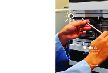
34826A getting started.book Page 10 Thursday, November 9, 2006 12:46 PM1Getting Started with Data Logger for 34980AGetting Started TutorialThis getting started tutorial introduces you to the Data Loggerfor 34980A and shows you how to: Connect to one or more 34980As Set up a simple channel configuration Scan channels and measure some data View the data in graphical form Export the data to a Microsoft Excel-compatible spreadsheet Save the configurationBefore starting the tutorial, you should become familiar withthe Data Logger for 34980A user interface. The graphic belowshows the menus, status area and tabs in the user interface.MenusStatus AreaTabs10Getting Started with Data Logger for 34980A
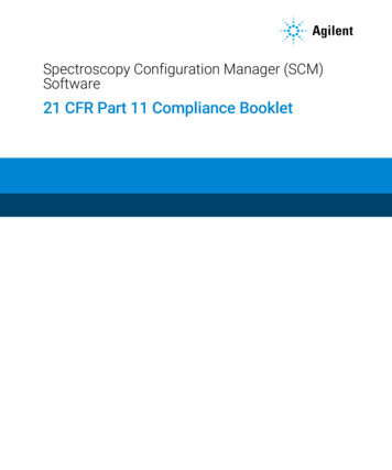
34826A getting started.book Page 11 Thursday, November 9, 2006 12:46 PMGetting Started with Data Logger for 34980A1Step 1. Create a New ConfigurationIn this step we will create a new configuration.NO TEFor purposes of example, this tutorial assumes you have a 34921A,34922A, 34923A, 34924A, or 34925A multiplexer module installed in a34980A. Although you can use up to two 34980As in a configuration, thistutorial uses only one 34980A. You should not have any channelsconnected to external equipment or signal sources for this tutorial.1 Click the Data Logger for 34980A icon on your desktop toopen the application.2 Click Configuration New. to create a new configuration.3 You will be prompted to enter a new configuration name andcomments. For this tutorial, enter the information shownbelow and click OK.Getting Started with Data Logger for 34980A11
34826A getting started.book Page 12 Thursday, November 9, 2006 12:46 PM1Getting Started with Data Logger for 34980AThe configuration name appears under Configuration: in thestatus area of the application window. For example:NO TE12Notice the unlocked padlock icon to the right of the configuration name.This indicates the configuration does not yet have a datalog and iseditable. Once a scan has occurred and a datalog exists for theconfiguration, the padlock will be shown as locked. To alter a lockedconfiguration, you must either delete the associated datalog(s) or copyand rename the configuration.Getting Started with Data Logger for 34980A
34826A getting started.book Page 13 Thursday, November 9, 2006 12:46 PMGetting Started with Data Logger for 34980A1Step 2. Configure 34980sIn this step you will identify which 34980A(s) to use in theconfiguration.Data Logger for 34980A can be used in either of these twomodes: Connected to 34980A (Connected Mode) Not connected to 34980A (Not Connected Mode)NO TEThis tutorial uses the Connected Mode and assumes your PC is connectedvia interface to at least one 34980A and communication has beenestablished. If you have not done so, you can use the Agilent ConnectionExpert to automatically configure interfaces and check 34980Acommunications. This utility is on the Automation-Ready CD ROMincluded with the 34980A.1 On the Configure 34980As tab, click Connected to 34980A.Notice on the Configure 34980As tab, the configurationsteps (1 through 4) are shown in bold lettering from left toright.NO TEYou can access the help for the selected tab by clicking the F1 key.2 Click the Add 34980s. button.3 Make sure the 34980s to be added are powered-on andconnected to the PC via an interface. In the Add 34980sdialog box, click the Find button.NO TEThe Find button will find only 34980As. It is not a general discovery tool forall devices on the interface.Getting Started with Data Logger for 34980A13
34826A getting started.book Page 14 Thursday, November 9, 2006 12:46 PM1Getting Started with Data Logger for 34980A4 You should now see a listing of the 34980As found. Forexample:The Find 34980A Status area shows the status of the findoperation. If you do not see any 34980As listed, check that theinterface is connected and the 34980A is powered-on. For moreinformation on troubleshooting configuration problems, refer tothe Agilent Connection Expert application on theAutomation-Ready CD ROM included with the 34980A.14Getting Started with Data Logger for 34980A
34826A getting started.book Page 15 Thursday, November 9, 2006 12:46 PMGetting Started with Data Logger for 34980A1Notice the License Status column. This column displays thelicensing status of the connected 34980A(s): If Licensed is displayed, the 34980A is properly licensed.You can continue with this tutorial. If Not Licensed, N Evaluations Remain is displayed, the34980A is not licensed but still has some evaluation runsleft. You can continue this tutorial in evaluation mode. Ifyou want to install license(s) now, clickTools Licensing Licensing Checklist and follow theinstructions. If Not Licensed, 0 Evaluations Remain is displayed, youneed to license the 34980A. ClickTools Licensing Licensing Checklist and follow theinstructions. Once licensed, you can continue this tutorial. If Instrument Firmware Update Required is displayed,the 34980A has outdated firmware. ClickTools Licensing Licensing Checklist and follow theinstructions. Once the firmware is updated, you cancontinue this tutorial.5 In the column labeled Select, click the box next to the34980A(s) you want to add. You can add up to two 34980Asin a single configuration.6 Click the Connect button. This reads the configuration of the34980A(s) and populates the Configure 34980As tab withthe 34980A number, address and modules found in the34980A.7 Double-click Instr1 in the Name column. Add a moredescriptive name for this 34980A. For this example, highlightInstr1 and enter the name Test Station 1.NO TEIt is best to rename the 34980A before starting a scan. Once scan data(datalog) exists, the Name field becomes locked.Getting Started with Data Logger for 34980A15
34826A getting started.book Page 16 Thursday, November 9, 2006 12:46 PM1Getting Started with Data Logger for 34980A8 Notice the Module Mode column. For modules that can beincluded in a scan (multiplexer and multifunction modules),this mode will be set to Scan Mode. Other modules thatcannot be included in a scan are set to Inactive Mode.Typically, for multiplexer and multifunction modules, youshould leave the Module Mode set to Scan Mode. If you wantto change the Module Mode, click in the field next to theright of the text and a drop down list will be available. Youmay choose Inactive Mode if you are not interested inscanning on a given module.NO TEAdditional modules are supported in Switch Mode. Refer to ModuleMode, in the online help, for details.9 Notice thebutton in the Properties column. Thisbutton opens the 34980A Properties dialog box which allowsyou to configure the 34980A, including changing the wiringmode (1-wire or 2-wire) of the 34923A and 34925A modules.16Getting Started with Data Logger for 34980A
34826A getting started.book Page 17 Thursday, November 9, 2006 12:46 PMGetting Started with Data Logger for 34980A1Step 3. Configure ChannelsIn this step you will add channels and measurement functionsto a scan list.1 Click the Configure Channels tab.NO TEWhenever you move from tab to tab or close the application, theconfiguration information is automatically saved.2 The 34980A number, name and modules are shown in thetree view in the column labeled Channels on the left side ofthe grid. You can collapse the tree view by clickingnextto a 34980A or module. Clickto expand a collapsed treeview.3 The Enable Channel column allows you to select channels tobe in the scan and, optionally, name each channel. To select achannel, click the checkbox in the Scan column under theEnable Channel column. For this tutorial, click the checkboxes next to channels 1001, 1002, 1003, 1004 and 1005.4 In the Name column, enter these names for the five selectedchannels: Power In, Low Load, High Load, Out Freq, OvenTemp.Getting Started with Data Logger for 34980A17
34826A getting started.book Page 18 Thursday, November 9, 2006 12:46 PM1Getting Started with Data Logger for 34980A5 The Measurement column allows you to select themeasurement function, the range, the resolution, and setadvanced measurement properties for each selected channel.The default measurement function for scanned channels isDC Voltage. To change the measurement function, click onthe word DC Voltage in the Measurement Function column.Click the down arrowfunctions:to see the available measurementFor this tutorial, set the measurement functions in sequence toDC Voltage, Four-Wire Ohms, Two-Wire Ohms, Frequency andTemp (Type B).NO TE18If your 34923A or 34925A multiplexer module is set to 1-wire mode, thefour-wire ohms function is not available. In this situation, set channel 1002to 2-wire ohms.Getting Started with Data Logger for 34980A
34826A getting started.book Page 19 Thursday, November 9, 2006 12:46 PMGetting Started with Data Logger for 34980ANO TE1Notice that for 4-wire ohms, a paired channel (channel n 20 for40-channel multiplexers or channel n 35 for 70-channel multiplexers) isautomatically configured for the sense lines.6 The Range column allows you to specify a fixed range orAutorange (the default). To change the range, click the wordAuto in the Range column. A drop down arrow appears,allowing you to select the range. For this tutorial, set theranges in sequence to: /- 1V, 10K, 100K, and Auto.NO TENotice the range for temperature measurements is fixed and displayed asNone.Getting Started with Data Logger for 34980A19
34826A getting started.book Page 20 Thursday, November 9, 2006 12:46 PM1Getting Started with Data Logger for 34980A7 The Res column allows you to set the measurementresolution for most measurement functions and thetemperature scale (C, K, or F) for temperaturemeasurements. To change the resolution, click the number5.5 in the Res column. A drop down arrow appears, allowingyou to select the resolution. For this tutorial, set theresolutions in sequence to: 5.5, 6.5, 5.5, 4.5 and F.20Getting Started with Data Logger for 34980A
34826A getting started.book Page 21 Thursday, November 9, 2006 12:46 PMGetting Started with Data Logger for 34980A18 The More column under Measurement allows you to selectadvanced settings for the measurement function. Forexample, for the DC Voltage function, you can set Number ofPower Line Cycles, Channel Delay and DC Input Resistance.For this tutorial, clickin the More column for channel1001, and set the Number of Power Line Cycles-NPLC to 10and click OK. This sets the integration time for the DMM.Notice the resolution for channel 1001 is now 6.5 digits—not5.5 digits. This is because integration time and measurementresolution are directly related.9 Optionally, you can use the Scaling (Mx B) column andAlarm Limits column to set scaling and alarms. We will notset scaling or alarms for this tutorial. Refer to the DataLogger for 34980A online help for more information onScaling (Mx B) or Alarms.Getting Started with Data Logger for 34980A21
34826A getting started.book Page 22 Thursday, November 9, 2006 12:46 PM1Getting Started with Data Logger for 34980AStep 4. Set Up Scan Control and Data ControlIn this step we will set the scan start and stop criteria anddefine when to log the data.1 Click on the Scan and Log Data tab—the channelconfiguration is automatically saved. The Scan and Log Datatab contains Scan Control, Scan Order, Data Control,Start/Stop and Scan Status sections. The default settingsstart the scan immediately.2 Typically, you will want to add more scan control to the scanthan starting immediately. Let's set the scan to start at aspecific time and stop after a number of scans.3 Clickin the Scan Control column. The Scan
Agilent BenchLink Data Logger for 34980A Getting Started Guide 1 Getting Started with Data Logger for 34980A Getting Started Tutorial 10 Step 1. Create a New Configuration 11 Step 2. Configure 34980s 13 Step 3. Configure Channels 17 Step 4. Set Up Scan Control and Data Control22 Step 5