Transcription
Category B1/B2 according Part-66 Appendix 1Module 8 Basic AerodynamicsPart 66 Cat. B1 / B2 Module 8BASIC AERODYNAMICSVilnius-2017Issue 1. Effective date 2017-07-28FOR TRAINING PURPOSES ONLYPage 1 of 74
Category B1/B2 according Part-66 Appendix 1Module 8 Basic AerodynamicsTable of ContentsPart-66 Module 8. Basic Aerodynamics (Cat. B1 and B2) Syllabus . 7Part-66: Appendix I - Basic Knowledge Requirements . 88.1 Physics of the Atmosphere . 9Atmosphere and Basic Aerodynamics . 9Temperature, Pressure and Altitude . 9Density. 12Humidity . 12Absolute Humidity . 13Relative Humidity and the Dew Point . 13International Standard Atmosphere (ISA) . 148.2. Aerodynamics . 17Airfoils . 17Terms Related to Air Stream around Airfoil . 18Upwash and Downwash . 18Turbulence . 19Stagnation Point and Stagnation Pressure . 19Boundary Layer, Laminar and Turbulent Flow . 19Free and Relative Flow/ Wind . 20The Airfoil Description . 21Angle of Attack . 21Angle of Incidence . 23Wing Area . 23Shape of the Airfoil . 24Airfoil Nomenclature . 25Thickness/Chord Ratio . 25Angle of Attack . 25The Wing Shape. 26Wing Span . 26Aspect Ratio . 26Wind Loading. 26Root Chord . 26Tip Chord . 26Swept Wing . 27Sweep Angle . 27Mean Aerodynamic Chord . 27Dihedral Angle . 28Issue 1. Effective date 2017-07-28FOR TRAINING PURPOSES ONLYPage 3 of 74
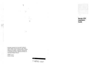
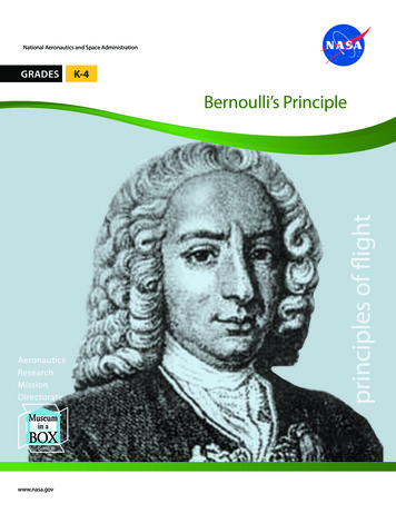
Category B1/B2 according Part-66 Appendix 1Module 8 Basic Aerodynamics8.1 PHYSICS OF THE ATMOSPHEREAtmosphere and Basic AerodynamicsAs an aircraft operates in the air the properties of air that affect aircraft control and performance mustbe understood.Air is a mixture of gases composed principally of nitrogen and oxygen. Since air is a combination ofgases, it follows the laws of gases. Air is considered a fluid because it answers the definition of afluid, namely, a substance which may be made to flow or change its shape by the application ofmoderate pressure. Air has weight, since something lighter than air, such as a balloon filled withhelium, will rise in the air.Air is made up of approximately 21% oxygen (O2) and 78% nitrogen (N) by volume, with theremaining 1% being made up from other gases. The ratios of the gases (21%, 78% and 1%) vary littlewith height although the moisture content drops with increase in altitude.Aerodynamics is the study of the dynamics of gases, or the interaction between moving object andatmosphere causing an airflow around a body. As first a movement of a body (ship) in a water wasstudies, it is not a surprise that some aviation terms are the same as naval ones – rudder, water line,keel beam, speed measured in knots (nautical miles).The understanding of basic aerodynamics – the possibility of flight, forces acting on aircraft in flight,why aircraft is designed with particular flight control systems, - is important for understanding themaintenance of aircraft systems.As a part of physics (gas laws, fluid dynamics and propagation of sound were studied in Module 2“Physics”) aerodynamics gives laws determining forces acting on aircraft and its behavior ininteraction with atmosphere.Temperature, Pressure and AltitudePhysically atmosphere is considered as a fluid of changing density, pressure and temperature.According to temperature changes with the height above the sea level atmosphere is divided intotroposphere, stratosphere, mesosphere and thermosphere (Fig. 1-1).As altitude increases, up to 30,000 feet (about 10 000 m), the temperature, pressure and density of theair decrease. This region is known as the TROPOSPHERE and the upper boundary is theTROPOPAUSE.Being minimal (about 60 C) at tropopause it rises up to 10 C at stratopause, and then decreasesto the altitude of about 80-85 kilometers (mesopause).These changes in temperature are very interesting as it is known the temperature of cosmicbackground is 455 𝐹𝐹 𝑜𝑜𝑜𝑜 273𝐾𝐾, but measurement show it depends on place of measurement –being in shadow or not.Issue 1. Effective date 2017-07-28FOR TRAINING PURPOSES ONLYPage 9 of 74
Category B1/B2 according Part-66 Appendix 1Module 8 Basic AerodynamicsFigure 1-1. Atmospheric Regions & RelationshipMore exactly the changes in temperature from sea level up to tropopause are presented on Fig. 1-2.Really the change in temperature from the sea level up to tropopause is almost linear and gives thevalues of 6.5 𝐶𝐶 for each 1 000 meters or 3.6 𝐹𝐹 per each 1 000 feet. This is called the standard (oraverage) laps rate.Figure 1-2. Changes in temperature with altitudeIf a 1-in. square column of air extending from sea level to the “top” of the atmosphere could beweighed, it would be found to weigh about 14.7 lbs. Thus, atmospheric pressure at sea level is 14.7PSI (pounds per square inch). However, pounds per square inch are rather a crude unit for themeasurement of a light substance such as air. Therefore, atmospheric pressure is usually measured interms of inches of mercury (Fig. 1-3) when measured with a mercury barometer or SI units.Issue 1. Effective date 2017-07-28FOR TRAINING PURPOSES ONLYPage 10 of 74
Category B1/B2 according Part-66 Appendix 1Module 8 Basic AerodynamicsFigure 1-5. Atmospheric pressure and attitude relationshipThe relation between different units is as follows:29.92 in Hg 1 atm 14.7 psi 1013.2 hPa 760 mm Hg 1.013 barThe last unit is that meteorologists use.DensityDensity is a term that means weight per unit volume. Since air is a mixture of gases, it can becompressed. If the air in one container is under one-half as much pressure as the air in anotheridentical container, the air under the greater pressure weighs twice as much as that in the containerunder lower pressure. The air under greater pressure is twice as dense as that in the other container.For equal weights of air, that which is under the greater pressure occupies only half the volume ofthat under half the pressure.The density of gases is governed by the following rules (gas Laws studied previously in M2 Physics):-Density varies in direct proportion with the pressure (under constant temp);-Density varies inversely with the temperature (under constant pressure).Thus, air at high altitudes is less dense than air at low altitudes (Fig. 1-4), and a mass of hot air is lessdense than a mass of cool air. Changes in density affect the aerodynamic performance of aircraft.With the same horsepower, turbine aircraft can fly faster at a high altitude where the density is lowthan at a low altitude where the density is great. This is because air offers less resistance to the aircraftwhen it contains a smaller number of air particles per unit volume.HumidityHumidity is the amount of water vapor in the air. The maximum amount of water vapor that air canhold varies with the temperature. The higher the temperature of the air, the more water vapor it canabsorb. By itself, water vapor weighs approximately five-eighths as much as an equal amount ofperfectly dry air. The last fact is due to difference in water (𝐻𝐻2 𝑂𝑂) and main air components (𝑁𝑁2 andIssue 1. Effective date 2017-07-28FOR TRAINING PURPOSES ONLYPage 12 of 74
Category B1/B2 according Part-66 Appendix 1Module 8 Basic Aerodynamics𝑂𝑂2 ) molecular weights. 𝐻𝐻2 𝑂𝑂 molecule molecular weight is 18 whereas 𝑁𝑁2 molecular weight – 28( 78% of air), and 𝑂𝑂2 molecular weight – 32 ( 20% of air). Therefore, when air contains water vaporit is not as heavy as air containing no moisture.Assuming that the temperature and pressure remain the same, the density of the air varies inverselywith the humidity. On damp days the air density is less than on dry days. For this reason, an aircraftrequires a longer runway for takeoff on damp days than it does on dry days.Absolute HumidityThe number of grams of water vapor per 1 𝑚𝑚3 of the atmosphere.Relative Humidity and the Dew PointExisting water vapor pressure of the atmosphere, expressed as a percentage of the saturated watervapor pressure at the same temperature.Air temperature drops as we rise in altitude above the surface. At some point the air temp drops tothe dew point of the air at which point the water vapor in the air condenses into liquid water, and thiswater we see condensed onto specs of dust in the air makes up the clouds. All air contains someamount of water vapor, varying from just a fraction of a percent (by weight) for cold dry desert air,on up to some 3% for hot steaming jungles.As the properties of air and water vapor are essentially independent, the property of the water – watervapor equilibrium (Fig. 1-6) at various temperatures is of great importance, but not the properties ofthe air.Figure 1-6. Air – saturation vapor pressure (According to The Engineering ToolBox)Having a jar of dry air, and poured some water into the bottom of it, water molecules on the surfacewill evaporate from the surface and periodically condense back into the surface until it reaches someequilibrium value where evaporation and condensation is equal. At that point the air in the jar willIssue 1. Effective date 2017-07-28FOR TRAINING PURPOSES ONLYPage 13 of 74
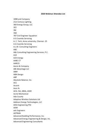
Category B1/B2 according Part-66 Appendix 1Module 8 Basic Aerodynamics8.2. AERODYNAMICSIn addition to definition given in sub-module 8.1 aerodynamics as the science describing body’smovement in an air. Thus it is a branch of dynamics which deals with the motion of air and othergases, with the forces acting upon an object in motion through the air, or with an object which isstationary in a current of air. In effect, in aviation aerodynamics is concerned with three distinct parts.These parts may be defined as the aircraft, the relative wind, and the atmosphere.AirfoilsAn airfoil is a surface designed to obtain a desirable reaction from the air through which it moves.Thus, we can say that any part of the aircraft which converts air resistance into a force useful for flightis an airfoil. The blades of a propeller are so designed that when they rotate, their shape and positioncause a higher pressure to be built up behind them than in front of them so that they will pull theaircraft forward. The model of a wing (Fig. 2-1) gives an excellent example of streamlines aroundairfoil.Figure 2-1. Streamlines around airfoilAlthough the top surface of the conventional wing profile has greater curvature than the lower surface,the principal thing is the larger density of streamlines above the wing. The larger density ofstreamlines means the greater velocity of air.According to Bernoulli’s principle (previously studied in Module 2 Physics) an increase in the speedof the fluid occurs simultaneously with a decrease in pressure or a decrease in the fluid's potentialenergy. This is equivalent to the principle of conservation of energy. This states that in a steady flowthe sum of all forms of mechanical energy in a fluid along a streamline is the same at all points onthat streamline.According Bernoulli’s principle the product 𝑃𝑃 𝑣𝑣 ��𝐴𝐴𝐴𝐴𝐴𝐴𝐴𝐴𝐴 𝑣𝑣𝐵𝐵𝐵𝐵𝐵𝐵𝐵𝐵𝐵𝐵 𝑃𝑃𝐵𝐵𝐵𝐵𝐵𝐵𝐵𝐵𝐵𝐵 sue 1. Effective date 2017-07-28FOR TRAINING PURPOSES ONLYPage 17 of 74
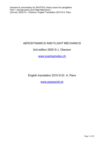
Category B1/B2 according Part-66 Appendix 1Module 8 Basic Aerodynamicsthat if the wing area is doubled, all other variables remaining the same, the lift and drag created bythe wing is doubled. If the area is tripled, lift and drag are tripled.Shape of the AirfoilThe shape of a wing (Fig. 2-10) consequently affects the efficiency of the wing.Figure 2-10. Airfoil typesAirfoil section properties differ from wing or aircraft properties because of the effect of the wingplanform. A wing may have various airfoil sections from root to tip, with taper, twist, and sweepback.The resulting aerodynamic properties of the wing are determined by the action of each section alongthe span.Efficiency of a wing is measured in terms of the lift over drag (L/D) ratio. This ratio varies with theangle of attack but reaches a definite maximum value for a particular angle of attack. At this angle,the wing has reached its maximum efficiency. The shape of the airfoil is the factor which determinesthe angle of attack at which the wing is most efficient; it also determines the degree of efficiency.Research has shown that the most efficient airfoils for general use have the maximum thicknessoccurring about one-third of the way back from the leading edge of the wing.High-lift wings and high-lift devices for wings have been developed by shaping the airfoils to producethe desired effect. The amount of lift produced by an airfoil will increase with an increase in wingchamber. Camber refers to the curvature of an airfoil above and below the chord line surface. Upperchamber refers to the upper surface, lower camber to the lower surface, and mean camber to the meanline of the section. Camber is positive when departure from the chord line is outward, and negativeswhen it is inward. Thus, high-lift wings have a large positive camber on the upper surface and a slightnegative camber on the lower surface. Wing flaps cause an ordinary wing to approximate this samecondition by increasing the upper chamber and by creating a negative lower chamber.It is also known that the larger the wingspan as compared to the chord, the greater the lift obtained.This comparison is called aspect ratio. The higher the aspect ratio, the greater the lift In spite of thebenefits from an increase in aspect ratio, it was found that definite limitations were of structural anddrag considerations.Issue 1. Effective date 2017-07-28FOR TRAINING PURPOSES ONLYPage 24 of 74
Category B1/B2 according Part-66 Appendix 1Module 8 Basic AerodynamicsDihedral AngleThe upward inclination of the wing to the plane through the lateral axis (Fig. 2-15).Figure 2-15. Dihedral angleAnhedral AngleThe downward inclination of the wing to the plane through the lateral axis (Fig. 2-16).Figure 2-17. Anhedral angleIssue 1. Effective date 2017-07-28FOR TRAINING PURPOSES ONLYPage 28 of 74
Category B1/B2 according Part-66 Appendix 1Module 8 Basic AerodynamicsThe total amount of drag on an aircraft is made up of many drag forces with three main:-Parasite drag;-Profile drag and-Induced drag.Parasite drag is made up of a combination of many different drag forces. Any exposed object on anaircraft offers some resistance to the air, and the more objects in the airstream, the more parasite drag.While parasite drag can be reduced by reducing the number of exposed parts to as few as practicaland streamlining their shape, skin friction is the type of parasite drag most difficult to reduce. Nosurface is perfectly smooth. Even machined surfaces when inspected under magnification have aragged uneven appearance. These ragged surfaces deflect the air near the surface causing resistanceto smooth airflow. Skin friction can be reduced by using glossy flat finishes and eliminatingprotruding rivet heads, roughness, and other irregularities.Profile drag may be considered the parasite drag of the airfoil. The various components of parasitedrag are all of the same nature as profile drag. The combination of induced and profile or form dragis shown on Fig. 2-27.Figure 2-27. DragThe action of the airfoil that gives us lift also causes induced drag. Remember that the pressure abovethe wing is less than atmospheric, and the pressure below the wing is equal to or greater thanatmospheric pressure. Since fluids always move from high pressure toward low pressure, there is aspanwise movement of air from the bottom of the wing outward from the fuselage and upward aroundthe wing tip. This flow of air results in “spillage” over the wing tip, thereby setting up a whirlpool ofair called a vortex (Fig. 2-28).Issue 1. Effective date 2017-07-28FOR TRAINING PURPOSES ONLYPage 35 of 74
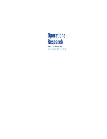
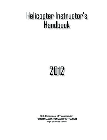
Category B1/B2 according Part-66 Appendix 1Module 8 Basic Aerodynamics8.3 THEORY OF FLIGHTAviation mechanic must understand the relationships between the atmosphere, the aircraft, and theforces acting on it in flight, in order to make intelligent decisions affecting the flight safety of bothairplanes and helicopters.Understanding why the aircraft is designed with a particular type of primary and secondary controlsystem, and why the surfaces must be aerodynamically smooth, becomes essential when maintainingtoday’s complex aircraftThe Forces Acting in FlightAs the air flows over the upper surface of an airfoil, its speed or velocity increases and its pressuredecreases. An area of low pressure is thus formed. There is an area of greater pressure on the lowersurface of the airfoil, and this greater pressure tends to move the wing upward. This difference inpressure between the upper and lower surfaces of the wing is called lift. Three-fourths of the total liftof an airfoil is the result of the decrease in pressure over the upper surface. The impact of air on theunder surface of an airfoil produces the other one-fourth of the total lift.An aircraft in flight is acted upon by four forces (Fig. 3-1):1. Gravity, or weight, the force that pulls the aircraft toward the earth;2. Lift, the force that pushes the aircraft upward;3. Thrust, the force that moves the aircraft forward;4. Drag, the force that exerts a braking action.Figure 3-1. Lift/Weight and Thrust/Drag pitching momentsCommon ConsiderationsLift acts through the centre of pressure and weight through the centre of gravity. For simplicity, thrustand drag forces are considered as acting parallel to the longitudinal axis, and their displacement fromIssue 1. Effective date 2017-07-28FOR TRAINING PURPOSES ONLYPage 43 of 74
Category B1/B2 according Part-66 Appendix 1Module 8 Basic Aerodynamicscarried out by actually transferring fuel from the main tanks in the wings to fuel tanks in the tail ofthe aircraft as in the A380. The CoG changes slightly as passengers move about the aircraft.Arrangement of the Four ForcesThe aircraft is designed so the four forces are arranged to make it reasonably stable. In straight andlevel flight at constant speed with no turning moments the aircraft is said to be in equilibrium. ThismeansTHRUST DRAG and WEIGHT LIFT.Each pair is equal and opposite in direction. Nevertheless they are not usually opposite in position.For straight and level flight the AA is adjusted by the pilot to make the lift equal to the weight, if it isgreater the aircraft will climb. If lift is less than weight the aircraft will descend. The engine thrust isadjusted by the throttles to make it equal to the drag, if it is greater the aircraft will increase airspeed- if it is less the aircraft's airspeed will decrease.The Perfect Interaction of Four ForcesFig. 3-1 and Fig. 3-4 shows the perfect interaction of the four forces. For various reasons some aircrafthave their forces in a not a perfect arrangement with thrust line higher than the drag line (as seaplanes).Figure 3-4. The perfect interaction of the four forcesThe ideal arrangement is where the CoG is forward of the CoL (CoP), which produces a nose downcouple - and the thrust line is lower than the CoD (Centre of Drag), which produces a nose up couple.In level flight each couple opposes the other and cancell each other out.Issue 1. Effective date 2017-07-28FOR TRAINING PURPOSES ONLYPage 47 of 74
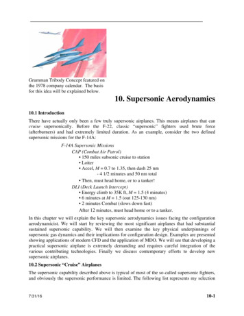
Category B1/B2 according Part-66 Appendix 1Module 8 Basic Aerodynamics8.4 FLIGHT STABILITY AND DYNAMICSAxes of an AircraftWhenever an aircraft changes its attitude in flight, it must turn about one or more of three axes. Fig.4-1 shows the three axes, which are imaginary lines passing through the center of the aircraft. Theaxes of an aircraft can be considered as imaginary axles around which the aircraft turns like a wheel.At the center, where all three axes intersect, each is perpendicular to the other two. The axis whichextends lengthwise through the fuselage from the nose to the tail is called the longitudinal axis. Theaxis which extends crosswise, from wing tip to wing tip, is the lateral axis. The axis which passesthrough the center, from top to bottom is called the vertical axis.Figure 4-1. Motion of an aircraft about its axesMotion about the longitudinal axis resembles the roll of a ship from side to side. In fact, the namesused in describing the motion about an aircraft’s three axes were originally nautical terms. They havebeen adapted to aeronautical terminology because of the similarity of motion between an aircraft anda ship.Thus, the motion about the longitudinal axis is called roll; motion along the lateral (cross-wing) axisis called pitch. Finally, an aircraft moves about its vertical axis in a motion which is termed yaw. Thisis a horizontal movement of the nose of the aircraft.Roll, pitch, and yaw - the motions an aircraft makes about its longitudinal, lateral, and vertical axes are controlled by three control surfaces. Roll is produced by the ailerons, which are located at theIssue 1. Effective date 2017-07-28FOR TRAINING PURPOSES ONLYPage 57 of 74
Category B1/B2 according Part-66 Appendix 1Module 8 Basic AerodynamicsFig. 4-5 shows a simplified aileron control system using push/pull rods, pulleys and cables and Fig.4-6 shows a simplified elevator control system using the same basic control system components.Figure 4-5. A simplified aileron control systemFigure 4-6. A simplified elevator control systemThe control systems of smaller aircraft are very similar to those shown but for larger /faster aircraftthe controls are powered (usually with hydraulically powered units at the control surface end beingsignalled by a mechanical control system from the flight-deck end).Some systems are fully computer controlled with signals to the computer coming from the pilot'sflight-deck controls. The powered units (usually hydraulic) get their signals from the computers.Fig. 4-4 to Fig. 4-6 help memorize the pilot's control movement, the control system movement andthe subsequent control surface/surfaces movement.Fig. 4-7 shows the control surfaces as fitted to an airliner. The slats are fitted to the complete lengthof the outer wing leading edge and the leading edge flaps are fitted to the inboard leading edge. Thetrailing edge flaps are fitted in-board of the ailerons.The ailerons are used for roll control (to bank the aircraft) - also to assist in improving the L/D ratioof the wing during take-off and landing by being drooped (automatically).When selected to the drooped position they are moved symmetrically (both sides move downtogether). Any movement as ailerons (asymmetric movement) is achieved about the new droopedneutral position.Issue 1. Effective date 2017-07-28FOR TRAINING PURPOSES ONLYPage 61 of 74
Category B1/B2 according Part-66 Appendix 1Module 8 Basic AerodynamicsDirectional StabilityThis is assisted by the fin and rudder and the side area of the fuselage aft of the Centre of Gravity taken all together called the Effective Keel Surface (Fig. 4-16).Figure 4-16. Effective keel surfaceIf the aircraft is caused to yaw then, like a weather-cock or weather vane on a church spire, the airflowwill „blow“ it back to it's original position.When aircraft yaws it will tend to fly in it's original direction for a short time due to it's momentum(Newton's 1st law – Law of inertia, as described in Module 2 Physics) - thus for a short time theairflow will be acting on the side of the fuselage. This correcting moment is also assisted by the smallsideways „lift“ produced by the fin.This correcting action may set up an oscillating motion which is corrected by fitting poweredautomatic yaw dampers to the rudder control system.For most aircraft the fin is vertical and its chord line is parallel to the aircraft's longitudinal datumline. For some single engined propeller driven aircraft, however, the fin chord line is set at a smallangle to the longitudinal datum line to counter the effect of the swirling propeller slipstream.Longitudinal StabilityThis is associated with the tail-plane or horizontal stabiliser. For many large passenger aircraft thetailplane may be designed with its maximum camber on the underside thus producing downwards lift.On some aircraft the chordline is set at a small negative angle to the longitudinal datum line (negativeangle of incidence) also to produce negative lift.Figure 4-17. Longitudinal stabilityIssue 1. Effective date 2017-07-28FOR TRAINING PURPOSES ONLYPage 68 of 74
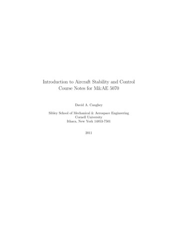
Category B1/B2 according Part-66 Appendix 1Module 8 Basic AerodynamicsHeavy DampingAn aircraft is said to be dynamically stable when it returns to it's original trimmed position with noovershoot (Fig. 4-20A). It's movement is said to be heavily damped. There are no oscillations and theaircraft returns steadily to it's original flight path. Because of the damped nature of the return it maytake some time to get back to its original position.Figure 4-20. Dynamic stabilityPartial DampingThis is where the aircraft returns to it's original trimmed position but overshoots (Fig. 4-20B). It isstable enough to correct this overshoot but moves back passed it's original position.These oscillationsgradually decrease in amplitude until the aircraft regains it's original flight attitude.UndampedIn this case (Fig. 4-20C) called neutral dynamic stability the aircraft returns to it's original flight pathand overshoots. It corrects this overshoot to return back to the same overshoot position but on theother side.These overshoots either side of the original flight path do not decrease or increase in amplitude butremain the same. This is not an uncommon condition with some aircraft stabilities and may requirethe fitment of auto-stabilising systems within the flying control system.Negatively D
The understanding of basic aerodynamics – the possibility of flight, forces acting on aircraft in flight, why aircraft is designed with particular flight control systems, - is important for understanding the maintenance of aircraft systems. As a part of physics (gas laws, fluid dynam