Transcription
Answers & commentary for SHV/FSVL theory exam for paraglidersPart 1: Aerodynamics and Flight Mechanics.(2nd ed.) 2005 J. Oberson, English Translation 2010 A. PiersAERODYNAMICS AND FLIGHT MECHANICS2nd edition 2005 J. Obersonwww.soaringmeteo.chEnglish translation 2010 Dr. A. Pierswww.paraworld.chPage 1 of 35
Answers & commentary for SHV/FSVL theory exam for paraglidersPart 1: Aerodynamics and Flight Mechanics.(2nd ed.) 2005 J. Oberson, English Translation 2010 A. PiersTable of ContentsVectors . 3Drag . 6Lift and Drag: Profile of a Flat Object Subjected to Wind. 10Profile of a wing. 13Polar Forces & Angle of Attack . 16Geometry of a Wing & Wing Loading. 18Equilibrium of Forces for a Glider in Normal Flight . 22Glide Ratio of a Wing . 23Axes and Flight Stability. 25Polar Speeds. 26Polar Speeds in Moving Air Mass . 29Equilibrium of Forces for a Glider while Turning & Load Factor. 32Page 2 of 35
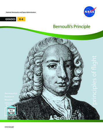
Answers & commentary for SHV/FSVL theory exam for paraglidersPart 1: Aerodynamics and Flight Mechanics.(2nd ed.) 2005 J. Oberson, English Translation 2010 A. PiersVectorsA vector is a representation of certain physical phenomena characterized by a magnitude,direction and point of origin. Two examples useful for the paragliding are (1) force and (2)speed. To characterize these two phenomena requires knowledge of the magnitude, forexample a force of 10 kg or 16 kg and a speed of 35 km/h, their origin (center of the objectthat is acted upon) and direction (in 2 or 3 dimensions).To graphically represent the two phenomena we use vectors depicted as arrows (or lines).Length of vector magnitude of physical phenomenon. If the scale is 1 cm 10 kgrepresented graphically, a vector of 3 cm will then correspond to a force of 30 kg.Origin of a vector end without the arrow. For example, this is the point of application offorce.Direction of a vector shown by the orientation arrow.Example (Figure A1): In depicting on paper a speed of 30 km/h by a vector V, applied onthe object X (center of the object X ') heading is north west.Figure A1: Example of a vector V representing a speed. If 1 cm represents an arbitrary 10 km/h then 3 cm 30 km/h . V goes to the NW and applies to the object X to point X '.When two vectors V1 and V2 act on an object, it effect is the same as if it were only actedon by the resultant vector R. This is called adding the two vectors. We cannot simply addup their length because it ignores the directions. Figure A2 shows the technique to addPage 3 of 35
Answers & commentary for SHV/FSVL theory exam for paraglidersPart 1: Aerodynamics and Flight Mechanics.(2nd ed.) 2005 J. Oberson, English Translation 2010 A. Piersthese 2 vectors.Figure A2: (1) Re-position V1 without changing orientation, so that the two origins of V1 and V2 coincide. (2)Draw a line parallel line to V2 (shown as S1). (3) Draw a line parallel to V1 (shown as S2). (3) The resultantvector R has its origin O and ends at the intersection X of the two parallels S1 & S2.Special cases: (1) Two vectors have the same orientation and the same direction, in thiscase simply add up their magnitudes. (2) Two vectors have the same orientation butopposite directions, then the resultant is the difference of the two vectors.For the 5 questions 001 to 005, the same basic chart is used: See Figure A3. On the leftthere are 5 examples of vectors F1 to F5. On the right there are 4 examples of resultantvectors R1 to R4.Figure A3: the basic graphic used for questions 1 to 5 (aerodynamics) of the SHV/FSVL paraglider pilottheory examination.Page 4 of 35
Answers & commentary for SHV/FSVL theory exam for paraglidersPart 1: Aerodynamics and Flight Mechanics.(2nd ed.) 2005 J. Oberson, English Translation 2010 A. PiersQuestion 001. Addition of F1 and F2. This is the special case where two vectors areparallel in the same orientation. See Figure A4. R corresponds to R3 Figure A3Figure A4: addition of F1 and F2Question 002. Addition of F1 and F3. This is the other special case where two vectors areparallel and in opposite. See Figure A5. R corresponds to R4 of Figure A3.Figure A5: addition of F1 and F3Question 003. Addition of F1 and F4. See Figure A6. R corresponds to R2.Figure A6: Addition of F1 and F4Question 004. Addition of F1 to F5. See Figure A7. R corresponds to R1.Page 5 of 35
Answers & commentary for SHV/FSVL theory exam for paraglidersPart 1: Aerodynamics and Flight Mechanics.(2nd ed.) 2005 J. Oberson, English Translation 2010 A. PiersFigure A7: addition of F1 and F5Question 005. Addition of F4 and F5. See Figure A8. R corresponds to R4.Figure A8: Addition of F4 and F5Note: You can add as vectors of the same type: eg two vectors of "force" but not differenttypes, eg. a vector of "speed" and vector of "force".DragWind: Moving air mass relative to fixed objects (houses, trees . etc.). In the exammultiple choice questions, this is also referred to as "airflow" or "flow".Relative wind: When travelling at a speed V in an air mass moving at the same speed,the sensation is the same if we remained motionless. When an object moves through air, itexperiences a relative wind.Drag: All objects in a wind (normal or relative) are also subject to a force called drag. Forany object this force has the same orientation as the wind. For example if you put a handoutside the window of a moving car, you feel a force pushing your hand backwards, in thePage 6 of 35
Answers & commentary for SHV/FSVL theory exam for paraglidersPart 1: Aerodynamics and Flight Mechanics.(2nd ed.) 2005 J. Oberson, English Translation 2010 A. Pierssame direction as the relative wind created by the speed of the car. Drag is expressed inkg or Newtons (N). 10N approximately 1kg.4 factors influence the drag of an object: (1) The surface area of the object exposed to thewind (2) wind speed, (3) the air density and (4) the shape of the object . There are noother significant factors. Note however that the exposed surface depends on the size ofthe object. See Figure A9 and question 006. None of the following influence the drag: theweight, density (or spefic gravity), mass, molecular construction ff the material of theobject, humidity, dew point, air temperature or pressure gradient (questions 006, 014,023, 032, 041). For question 041, the proper response; "surface characteristics" includesboth the object's surface exposed to the wind and the shape of the object.(1) Exposed Surface: The exposed surface perpendicular to the direction of the wind thusdepends on the volume and size of the object. The greater the exposed surface, thegreater the. See Figure A9. (Question 006).Figure A9: The surface S of the object O in wind V is smaller than the surface S 'of the object O' itself greaterthan O.The relationship between drag and the exposed surface is linear: When the exposedsurface doubles, (or quadruples or halves), the drag doubles, (or quadruples or halves.Questions 007 to 009. See Figure A10.Page 7 of 35
Answers & commentary for SHV/FSVL theory exam for paraglidersPart 1: Aerodynamics and Flight Mechanics.(2nd ed.) 2005 J. Oberson, English Translation 2010 A. PiersFigure A10: For the same wind V, if the surface of an object exposed to the wind while doubles, the drag (F)will double also.Further example: If the exposed surface of an object in a wind (V) increases from 2m2 to4m2, this doubles the exposed surface and therefore the drag also doubles. If the drag was300N (Newtons), it will now be 600N. The fact that the wind is 30 km/h and that everythingoccurs at sea level is irrelevant to the problem and is included in the question to test thestrength of your knowledge. (Question 010). Similar examples: if the surface is changed(i) from 2m2 to 1m2 (halves), (ii) from 8m2 to 2m2 (decreases of a factor 4) or (iii) 0.5m2 to3m2 (6-fold increases), the drag changes respectively from (i) 300N to 150N (halves), (ii)1200N to 300N (reduced by a factor 4) or (iii) 150N to 900N (increases by a factor of 6).Questions 011 to 013.(2) Wind Speed: For the variations in wind speed, the effect is a less simple. Therelationship between wind speed and drag is not linear. In other words, if the speedincreases, drag increases much more. More specifically, the drag increases in proportionto the square of the speed. See Figure A11. More concretely, if the wind speed (air flow)exerted on the object increases by a factor of 2, the drag is multiplied by 22 (2 squared) 4. Question 015.Figure A11: For an identical surface, if the wind speed (V) doubles, the drag (F) experienced by the objectthen quadruples (4F) in the higher wind.Examples: If the wind speed (i) triples, (ii) quadruples or (iii) halves, the drag is multipliedby (i) 9. (ii) 16 or (iii) divided by 4, respectively. Questions 016 to 018. Another morePage 8 of 35
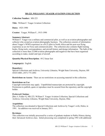
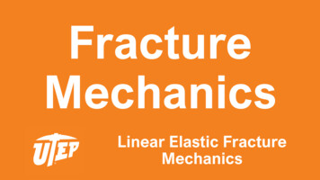
Answers & commentary for SHV/FSVL theory exam for paraglidersPart 1: Aerodynamics and Flight Mechanics.(2nd ed.) 2005 J. Oberson, English Translation 2010 A. Piersconcrete example: If the wind speed increases from 30 to 60km/h (doubles its speed), thedrag quadruples: If it was 300N (Newtons), it will be 1200N. The fact that the exposedsurface is 2m2 and that everything happens at sea level does not change the problem.Question 019. Similar Examples: If the wind speed increases from (i) 30 to 90km/h(triples), (ii) 80 to 40km/h (halves) or (iii) 20 to 60km/h (triples), whatever the surfaceexposed to the wind, the drag will change from (i) 100 to 900N (x 32), (ii) 1200 to 300N (x0.52) or (iii) 100 to 900N (x 32). Questions 020 to 022.(3) Air Density: As for the exposed surface, the relationship between air density and thedrag is linear. See Figure A12.Figure A12: If the surface (S) and wind (V) are identical, and if the density (D) of the air doubles, then drag(F) the object experiences in the wind will double also (2F).If the air density (i) doubles or (ii) halves, then the drag (i) doubles or (ii) halvesrespectively. Questions 024 and 025.In what circumstances does the air density vary in practice? The density of air (and airpressure) decreases with increasing altitude. In other words, the air is thinner with altitude.Example: if all other conditions identical, and if an object moves away from the Earth'ssurface (ie the object gains altitude), the density of air decreases as does the drag.Question 026. The relationship between altitude and air density is not quite linear. Themore higher the initial altitude the more slowly the air density decreases with increasedaltitude. In other words, if a body subjected to wind moves away from the Earth's surface(i.e. climbs), the drag decreases faster in the lower layers than at higher altitudes.Question 027. The factors should be remembered by heart for the examination: at 1100,2200, 3300 and 4400m. altitude, the air density (and therefore the drag) of an objectsubjected to varying wind speed changed by respectively 90, 81, 72, 64% versus the valueat sea level. Questions 028 to 031. Memory aid tip: the sum of height & density equals100 approximate altitudes (in hundreds of m) 10, 20, 30, 40 the approximate densitiescorresponding (in% of air density at sea level) are 90, 80, 70, 60%.(4) Object Shape: For an exposed area of the same object, an "aerodynamic" aspectoffers less resistance (less drag) than a less aerodynamic. See Figure A13. The impact ofshape on the drag of an object is determined by the “drag coefficient” (Cx). Question 033.For example, the object (a) with a flat surface perpendicular to the airflow (wind) has adrag coefficient of 1, the convex object (b) offers greater wind resistance is therefore aPage 9 of 35
Answers & commentary for SHV/FSVL theory exam for paraglidersPart 1: Aerodynamics and Flight Mechanics.(2nd ed.) 2005 J. Oberson, English Translation 2010 A. Piershigher drag coefficient (Cx) of 1.3. The “aerodynamic” object (c) has a very small dragcoefficient (Cx) of 0.08 while the object (d) good aerodynamic shape but not optimallyaligned has drag coefficient (Cx) of 0.17. Questions 037 to 040. Other applications: Underthe same conditions of wind and exposed surface, object with a drag coefficient of 1.3 willbe 1.3x larger than that of an object with a drag coefficient of 1. The drag of the first objectwill be 30% higher. Question 034. A body with a drag coefficient (Cx) of (i) 0.33 or (ii)0.05, will have approximately (i) 3x or (ii) 20x less drag compared to a body with a dragcoefficient (Cx) of 1. Questions 035 and 036.Figure A13: For identical surfaces and wind (V), the drag (F) varies depending on the shape of the objectsubjected to the wind. For example, the object (b) has drag 1.3x larger than the object of (a) and (c) has adrag of 0.08x vs. that of d.When an object is elongated and flat (eg a wing) and subjected to an oblique wind, twoperpendicular forces act on the object: The drag, parallel to the wind in the same direction,(like any object), and lift, perpendicular to the wind, toward the top surface. See FigureA14.Page 10 of 35
Answers & commentary for SHV/FSVL theory exam for paraglidersPart 1: Aerodynamics and Flight Mechanics.(2nd ed.) 2005 J. Oberson, English Translation 2010 A. PiersFigure A14: Drag (T) and Lift (P) of a flat object under an oblique wind (V).a upper surface, b bottom surface.As the with only drag, for any object we find the same 4 factors that influence lift and dragof a flat object: (1) The exposed surface of the object (2) wind speed (3) the density of airand (4) the shape and angle to the wind (angle of attack) of the object.If the surface or the air density doubles or halved, drag and lift double or are halved. If thewind speed doubles, the lift and drag are multiplied by four (the lift and drag increase withthe square of wind speed).For item 4, the coefficients of drag and lift, (respectively Cx and Cz) depend not only onthe shape of the object (Figure A15) but also the inclination of the flat object relative to thedirection wind (Figure A16). This is called the angle of attack.Page 11 of 35
Answers & commentary for SHV/FSVL theory exam for paraglidersPart 1: Aerodynamics and Flight Mechanics.(2nd ed.) 2005 J. Oberson, English Translation 2010 A. PiersFigure A15: Drag (T) and Lift (P) or Cx and Cz, respectively, of a flat object under oblique wind (V): Themore the profile of the object resembles an aerodynamic wing, the more P (or Cz) becomes large relative toT (or Cx).Figure A16: Drag (T) and Lift (P), respectively, or Cx and Cz, a flat object under oblique wind V, dependingon the impact. a nil effect: P and T zero very low. b low impact: P maximum and T low. c averageincidence: P and T by means. d maximum effect (perpendicular to the wind): P & T no maximum.We can now answer questions 050 and 056:Question 050. The lift depends on the angle of attack. There is a “trap” in the selection ofanswers: namely that the surface profile is not relevant and it should not be confused withthe exposed surface of the object in the wind.Question 056. The lift depends on 4 factors: size of the wing, lift coefficient, air density,and wind speed.Distribution of lift: lift can be broken into many vectors distributed around the profile of awing with a low angle of attack to the wind. See Figure A17. Three comments:(1) On the top surface, it's a phenomenon of suction (negative pressure) as if the wing wasbeing sucked by a vacuum cleaner so that the underside experiences positive pressure,as a fan blowing on the face. This difference in pressure between the upper and lowersurfaces results in spiral air movements at the wing tips (called a vortex or vortices). ThePage 12 of 35
Answers & commentary for SHV/FSVL theory exam for paraglidersPart 1: Aerodynamics and Flight Mechanics.(2nd ed.) 2005 J. Oberson, English Translation 2010 A. Piersvortices are formed as the upper-surface and lower-surface air pressures attempt tocompensate at the wind tips. Question 097. The vortecies cause increased drag, resultingin a lower performance of the wing as well as turbulence in its wake. So behind the trailingedge is the greatest turbulence generated by a glider. Question 098.(2) The negative pressure (suction) is about twice that of positive pressure experienced bythe underside. With an angle of attack of 10 , the distribution of lift is 2/3 on the uppersurface and 1/3 on the lower surface. Question 054.(3) There is also an asymmetric distribution of lift from front to back. The 2/3 of the lift is onthe front 1/3 of the wing. Question 055.Figure A17: Breakdown of aerodynamic forces around a wing profile.E negative pressure upper surface, I positive pressure lower surface.ProfileofawingThe profile of a wing is the shape of the longitudinal section (front to back) of the wing.Figure A18. The profile of the wings of gliders currently is quite thick and very asymmetricwith a curved top surface especially on the anterior third of the wing and a lower surfaceslightly convex. Question 048. The profile is one of the important elements that define thecharacteristics, including flying and kiting performace. Question 047.Page 13 of 35
Answers & commentary for SHV/FSVL theory exam for paraglidersPart 1: Aerodynamics and Flight Mechanics.(2nd ed.) 2005 J. Oberson, English Translation 2010 A. PiersFigure A18: Profile of a wing.Figure A19: Segments and significant geometric points of a profile.Page 14 of 35
Answers & commentary for SHV/FSVL theory exam for paraglidersPart 1: Aerodynamics and Flight Mechanics.(2nd ed.) 2005 J. Oberson, English Translation 2010 A. PiersSignificant geometric points of a profile:See Figure A20. Questions 042-046 and 049. Measurement (a): median chord of the profile, between (d) and (e)Measurement (b): length of the profile, close to, but less than (a).Measurement (c): thickness of the profile.Point (d): the trailing (rear) edge.Point (e): the leading (front) edge.Angle of attack (i): Angle between the direction of airflow (relative wind) and the medianchord of the profile (a).Significant aerodynamic points of a profile:See Figure A20. Questions 062-065, 068 and 071.Figure A20: Significant aerodynamic points of a profile. Point of stagnation or breakpoint (a): the point on the leading edge where the airstreams divide between the upper and lower surfaces.Center of thrust (b): the point where all the aerodynamic forces (lift and drag) effectivelyact.Stall point (c): the point on the upper surface where the airflow detaches from thesurface of the wing and after which turbulence occurs and leads to a negativecomponent of lift. This occurs mainly at large angles of attack.These points are aerodynamic not fixed geometrically. Rather they move as the angle ofattack varies. For example, the point of stagnation. Questions 069 and 070. See FigureA21. When the (already positive) angle of attack of a wing increases, the point ofstagnation on the lower surface moves toward the leading edge: figure A21 (right).Conversely, when the (already positive) angle of attack of a wing decreases, point ofstagnation moves toward the trailing edge: figure A21 (left).Page 15 of 35
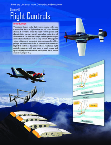
Answers & commentary for SHV/FSVL theory exam for paraglidersPart 1: Aerodynamics and Flight Mechanics.(2nd ed.) 2005 J. Oberson, English Translation 2010 A. PiersFigure A21: Moving the point of stagnation with changes in the angle of attack.Right, angle of attack (i) increases and left decreases.PolarForces&AngleofAttackThe distribution of forces (lift and drag) depends on the angle of attack. Figure A22.Questions 051-053. In (a), we find the optimum effect (10-15 ), with a significant lift and reduced dragthrough low pressure on the upper and the lower surface pressure consistent andeffective. In (b), the impact is significant: The lift is reduced and the drag increased. A stall point(X) (see also Figure A20) appears on the upper surface. Behind this point, turbulenceresults in a component of downward pressure downwards which replaces the negativepressure. In (c), the impact is detrimental. Airflow causes the lower surface to have negativepressure, and a positive pressure on the upper surface. With both effects actingdownwards, the profile now has a negative lift. In (d) the angle of attack is zero. While a drag continues, the negative pressure persistson the upper surface, and to a lesser extent, the lower surface. These forces opposeeach other and result in a very small lift.Figure A22: Breakdown of aerodynamic forces around a profile based on angle of attack.Multiple examples of could be provided to illustrate this effect, but it is more helpful andconcise to represent the relationship between lift-drag and angle of incidence (angle ofattack) by a graph called a “polar curve”. See Figure A23. The values on the graph arePage 16 of 35
Answers & commentary for SHV/FSVL theory exam for paraglidersPart 1: Aerodynamics and Flight Mechanics.(2nd ed.) 2005 J. Oberson, English Translation 2010 A. Piersonly orders of magnitude for illustrative purposes and should not be assumed to beaccurate.Figure A23: Polar aerodynamic forces. The values 5 , 10 , 15 , 20 and 25 represent the variousimplications degree (magnitude).The relationship between lift and drag of a wing (profile) depends primarily on the angle ofattack. Question 061. At about 10 the ratio between lift and drag is at its maximum whichcorresponds to the maximum efficiency and the best glide angle. By increasing the angleof attack, the lift increases, but drag increases to a greater extent. At 20 , the lift is at itsmaximum, but with the accompanying effect of a relatively high drag. This corresponds tothe minimum sink rate. At 25 , the lift disappears and the wing stalls (i.e. it is no longerflying). On the graph, we see that beyong the point of maximum efficiency, if the angle ofattack is reduced or increased, then Cz (or lift) decreases or increases respectively.Questions 058 and 060.Page 17 of 35
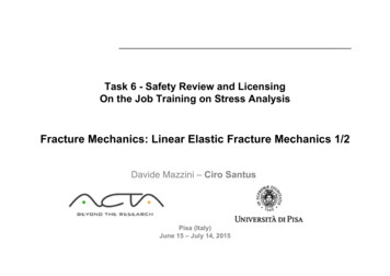
Answers & commentary for SHV/FSVL theory exam for paraglidersPart 1: Aerodynamics and Flight Mechanics.(2nd ed.) 2005 J. Oberson, English Translation 2010 A. PiersGeometryofaWing&WingLoadingWingspan: spread (length) between the two ends left and right wing. Question 072. It isgenerally expressed in m. We distinguish the wingspan "flat" (actual), measured on a wingspread the floor and a wingspan measured on the projected ground projection (shadow) ofthe wing inflated. See Figure A24. The "flat" span is obviously always greater than theprojected wingspan.Area: total area of the wing. It is generally expressed in m2. We can see the surface area"flat" (actual), measured on a wing spread the floor and the projected area, measured onthe vertical projection (shadow) of the inflated wing. See Figure A24. Question 101. The"flat" surface area is greater than the projected or possibly identical for a very flat wing.Figure A24: Area and wingspan of a “flat” and projected wing.E “flat” span, Ep projected span, S “flat” Area, Sp projected areaPage 18 of 35
Answers & commentary for SHV/FSVL theory exam for paraglidersPart 1: Aerodynamics and Flight Mechanics.(2nd ed.) 2005 J. Oberson, English Translation 2010 A. PiersTake-off weight: the sum of all the weight carried by the wing, i.e. pilot, glider, harnessand everything in it. It is generally expressed in kg.Wing load Take-off weight - weight of the wing; that is to say the total weight carried bythe wing. Partial answers to questions 085, 086, 089 and 090: Maximum Take-off weightof a wing of 5 kg with a maximum load of 95 kg 5 kg 95 kg 100 kg. Minimum take-offweight of a wing of 5kg with a minimum load of 70kg 5kg 70kg 75kg. (This is atypical example for paragliding). Maximum Take-off weight of a wing of 35kg with amaximum load of 90kg 35kg 90kg 125kg. Minimum take-off weight of a wing of 35kgwith a minimum load of 65kg 35kg 65kg 100kg. (This is a typical example for deltawing).Wing loading: Average load (weight) per unit area. Questions 075 and 076. It isexpressed in general kg/m2. Wing loading is obtained by dividing the take-off weight by thewing area (usually the projected area). For gliders, the wing loading is usually between 2.5and 4kg/m2. Examples of the calculation (questions 085, 086, 089 and 090): Calculatethe wing loading of a wing of 25m2. Max. 95kg, min. 70kg load. 5kg weight of the wing.(This is typically a paraglider). With a maximum load, the wing loading max. take-offweight / 25m2 (95kg 5kg) / 25m2 4 kg/m2. With a minimum load, the wing loading min. take-off weight. / 25 m2 (70kg 5kg) / 25m2 3kg/m2. Calculate the wing loading ofa wing of 12.5m2. Max. 90kg, min. 65kg load. 35kg weight of the wing. (This is typical of adelta wing). With a maximum load, the wing loading max. take-off weight / 25 m2 (90kg 35kg) / 12.5 m2 10kg/m2. With a minimum load, the wing loading min. take-off weight/ 25 m2 (70kg 35kg) / 12.5 m2 8kg/m2.Average depth: average difference between the leading edge and trailing edge of thewing. Question 073. It is expressed in general meters. See Figure A25. The relationshipbetween the surface area (S) and the average depth (p) and wingspan (e): S p x e orp S/e.Figure A25: wingspan (E) and average depth (Pm) of a wing.For example, if a wing has a wingspan of 10m and an area of 25m2, the average depth is25m2 / 10m 2.5m. Question 084. The values of weight and load data in the statement ofthis question are of course irrelevant. Another example: if a wing has a wingspan of 10mand an area of 12.5m2, the average depth is equal to 12.5m2 / 10m 1.25m. (QuestionPage 19 of 35
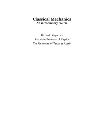
Answers & commentary for SHV/FSVL theory exam for paraglidersPart 1: Aerodynamics and Flight Mechanics.(2nd ed.) 2005 J. Oberson, English Translation 2010 A. Piers088).Wing torsion: Changes in angle of attack between different sections of the wing. SeeFigure A26. Question 074. In general twisting of the wing gives better stability of the wingand/or less need for pilot intervention in flight, particularly stalls are less likely and lessabrupt.Figure A26: twisting of a wing. I’ iAspect ratio: Ratio of average area and depth, ie area/mean depth e / p. Question 077.Calculation:e / p (e2) / (p x e) wingspan squared / areaIn fact, the product p x e (wingspan x average depth) is just the area of the wing. SeeFigure A25. Question 078. The latter formula wingspan2/area is more practical. For the“effective” aspect ratio (flat wing), we take the actual (“flat”) values of the wingspan and thearea. For the “projected” aspect ratio, we longer we take the projected values of thewingspan and area. With experience and practice, it is easy to recognize, at first glance, ahigh aspect ratio wing as having a modest elongation. The high aspect ratio wingstherefore have a large wingspan and a small average depth. The wings are therefore alittle longer with much smaller average depth. Figure A27. Questions 079 and 080.Page 20 of 35
Answers & commentary for SHV/FSVL theory exam for paraglidersPart 1: Aerodynamics and Flight Mechanics.(2nd ed.) 2005 J. Oberson, English Translation 2010 A. PiersFigure A27: a b large and small aspect ratiosWhen the aspect ratio is large, the wing tip vortices are important and induced drag islarge, which improves the performance of the wing in flight.The aspect ratio of current paragliders is around 5, that of a delta wing is typically 8.Questions 091 and 092.A wing whose aspect ratio 5 will have a major axis 5 times larger than its average depthor average depth of 5 times smaller than its area. Questions 081 and 082.Examples of calculations: Questions 083 and 087. Calculate the aspect ratio of a wing of10m wingspan and 25m2 area. Weights and load data are used in the statement only tomislead you and to test the strength of your knowledge. Aspect ratio 10m x 10m / 25 m2 100 / 25 4. Calculate the aspect ratio of a wing of 10m wingspan and 12.5m2 area.Aspect ratio 10m x 10m / 12.5m2 100 / 12.5 8.Another example: given the following characteristics of 4 wings (paragliders):a) Area 32 m2, 8 meter wingspanb) Area 25 m2, 10 meter wingspanc) Area 20 m2, 10 meter wingspand) Area 24 m2, 12 meter wingspanFind the wing with highest aspect ratio and the wing with the lowest aspect ratio.Questions 093 and 094. The smallest aspect ratio is easy to find, because the surface islarger (32m2) and the smallest wingspan (8m.). For largest aspect ratio, is evidently (c) or(d) because the areas are smaller and wingspan longer.For (c): aspect ratio 10m x 10m / 20 m2 5For (d): aspect ratio 12m x 12m / 24 m2 144 / 24 6So the largest aspect ratio is (d) 6.Another example: is given the characteristics of 4 wings (delta):a) Area 16 m2, 12 meter wingspanb) Area 20 m2, 10 meter wingspanc) Area 12 m2, 12 meter
case simply add up their magnitudes. (2) Two vectors have the same orientation but opposite directions, then the resultant is the difference of the two vectors. For the 5 questions 001 to 005, the same basic chart is used: See Figure A3. On the left there are 5 examples of vectors