Transcription
WeldingProcedureGuideAn easy to follow guide covering the preparation of weldingprocedure data sheets Copyright 2008 CWB Group - Industry Services
Copyright CWB Group - Industry ServicesRevised September 2008All rights reserved.CWB Group1-800-844-6790www.cwbgroup.org
TABLE OF CONTENTS1.0 Introduction22.0 Welding Engineering Standards33.0 Welding Procedure Specification (WPS)34.0 Welding Procedure Data Sheet (WPDS)44.1BLOCK 1 (General Information)64.2BLOCK 2 (Process information)74.3BLOCK 3 (Joint information)84.4BLOCK 4 (Technical data)114.5BLOCK 5 (Joint preparation)134.6BLOCK 6 (Base and Filler material)144.7BLOCK 7 (Welding details)164.8BLOCK 8 (Final remarks)205.0 Submission Of Welding Procedures236.0 Review And Approval Of Welding Procedures247.0 Sample Welding Procedure Data Sheets26 Copyright CWB Group - Industry Servicesii
Copyright CWB Group - Industry Services
WELDING PROCEDURE PREPARATION 1.0IntroductionThis guide has been prepared to assist welding personnel with the preparation of welding proceduresrequired as part of their company certification to CSA Standards W47.1, W47.2 and W186.The following three documents will be described:(a) Welding Engineering Standards (Note: Only required for W47.2)(b) Welding Procedure Specificationsc) Welding Procedure Data SheetsThere will be a brief description of the first two documents; however, this guide will focus on the preparationof welding procedure data sheets. Each item on the welding procedure data sheet will be described andguidance will be provided to complete each section. Copyright CWB Group - Industry ServicesPage 1
WELDING PROCEDURE PREPARATION 2.0Welding Engineering StandardsWelding engineering standards cover the design of welded joints encountered by the fabricator andprepared primarily for the fabricator’s engineering and drafting personnel.The welding engineering standards typically include:(a) Illustrated profiles of each typical joint intended for use, showing:(i) The type of joint (eg, butt, lap, tee, corner, edge);(ii) The type of weld;(iii) The geometry of the preparation and fit-up;(iv) The standard welding symbol;(v) The range of thickness; and(b) Minimum permissible sizes of fillet and partial penetration groove welds.Welding symbols shall be as shown in AWS Standard A2.4.Sample welding engineering standards are available on our website www.cwbgroup.org3.0Welding Procedure Specification (WPS)All companies applying or certified to CSA Standards W47.1, W47.2 or W186 are required to prepare andsubmit welding procedure specifications to the CWB for acceptance.A welding procedure specification (WPS) sets broad guidelines for the shop and field welding practice ofthe fabricator for each anticipated combination of essential variables. Welding parameters and ranges arespecified and used to prepare the associated welding procedure data sheets.Page 2 Copyright CWB Group - Industry Services
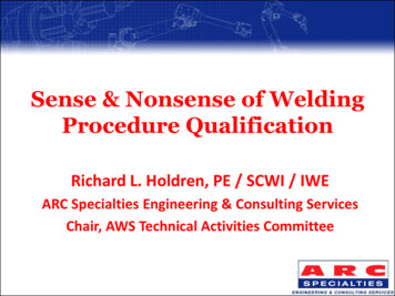
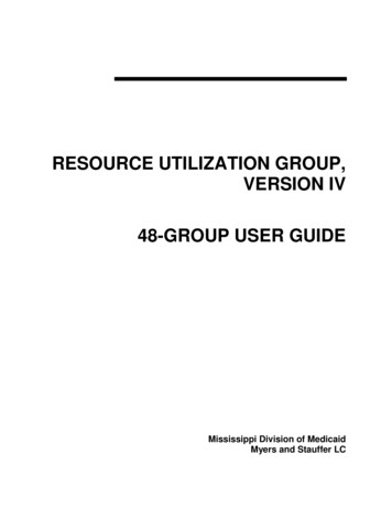
WELDING PROCEDURE PREPARATION The company shall have welding procedure specifications for each welding process in use, outlining thegeneral welding procedure to be followed in the construction of weldments built in accordance with thegoverning design or manufacturing standard, or both. Welding procedure specifications submitted foracceptance should cover as a minimum the items specified in Appendix D of CSA Standard W47.1 orAppendix A of CSA Standard W47.2, as applicable. Each welding procedure specification shall includeapplicable essential variables. All welding procedure specifications shall be submitted to the Bureau foracceptance and when stamped as accepted shall be considered as registered with the Bureau.Sample welding procedure specifications are available on our website www.cwbgroup.org4.0Welding Procedure Data Sheet (WPDS)A welding procedure data sheet (WPDS) is a document, used in conjunction with a WPS, detailing thewelding parameters and ranges for welding a specific joint, over a range of thicknesses and weld sizes, asillustrated on the data sheet. The following is the standard welding procedure data sheet form suggested bythe CWB, however, other welding procedure data sheet formats may be used. Each item on the data sheetwill be described and guidance on the completion of the form will be given. Common errors in completingthe form will be identified. Copyright CWB Group - Industry ServicesPage 3
WELDING PROCEDURE PREPARATION Page 4 Copyright CWB Group - Industry Services
WELDING PROCEDURE PREPARATION 4.1BLOCK 1 (General Information)Company name and addressEnter the complete company name and address in this section. If the data sheets are to be used bytwo or more certified plants within the same company the applicable plants need to be identified in thedocumentation submitted.WPDS No.Each company should have its own method of numbering welding procedure data sheets. This can rangefrom a relatively simple consecutive number system to one that identifies the process, position, groove typeand electrode. Each welding procedure data sheet number should be unique so that the WPDS can beeasily referenced on production schedules, work orders, shop drawings etc.Date and RevisionEnter the date the welding procedure data sheet was prepared and the revision number.Reference StandardsSome welding standards that may be referenced are:W47.1 – Certification of Companies for Fusion Welding of SteelW59 – Welded Steel Construction (Metal Arc Welding)W186 – Welding of Reinforcing Bars in Reinforced Concrete ConstructionW47.2 – Certification of Companies for Fusion Welding of AluminumW59.2 – Welded Aluminum ConstructionAWSD1.1 – Structural Welding Code - SteelAWSD1.3 – Structural Welding Code – Sheet SteelAWSD1.6 – Structural Welding Code – Stainless SteelA common combination is W47.1 and W59. For certified companies, there must always be a certificationstandard stated (eg. W47.1, W47.2,W186) plus a “Construction” standard (eg. W59, W59.2, D1.3, D1.6). Copyright CWB Group - Industry ServicesPage 5
WELDING PROCEDURE PREPARATION Reference WPSRecord the welding procedure specification number that applies to this data sheet.Some common mistakes with Block 1: The company name and address are not completed. More than one data sheet has the same identification number. No reference code is specified. Reference codes are specified that have different qualification rules and essential variables. Forexample W59 and D1.3.4.2BLOCK 2 (Process information)Welding ProcessesThe welding process to be used should be specified in this section. If two welding processes are usedto weld the joint they can be each be entered in the areas identified “1” and “2”. Some of the commonprocesses used are listed below with their corresponding letter designations:ProcessLetter DesignationShielded Metal Arc WeldingSMAWGas Metal Arc WeldingGMAWFlux Cored Arc WeldingFCAWMetal Cored Arc WeldingMCAWGas Tungsten Arc WeldingGTAWSubmerged Arc WeldingSAWPlasma Arc WeldingPAWElectroslag WeldingESWElectrogas WeldingEGWStud WeldingSWThe letter designation may be used to identify the process.Full details about the various welding processes can be found in the CWB modules.Page 6 Copyright CWB Group - Industry Services
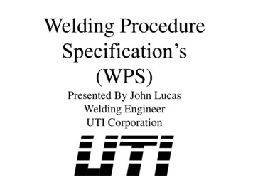
WELDING PROCEDURE PREPARATION PulsedIf pulsed current is used check this box. Enter the root mean square (RMS) current in block 7 and the peakand background current in the remarks section of block 8. The pulsed power source brand, model nameand the applicable program number should also be noted in the remarks section (Block 8).Shielding Gas typeRecord the complete generic composition or gas trade name as shown on the label on the gas cylinder.Use of the generic composition is advantageous as it allows the user to change brands of shielding gaswith the same composition with no required changes to the WPDS.Note: If the trade name is used, a change to another brand name, even if it is of identical composition, willrequire revised data sheets.The gas manufacturer/supplier may be able to provide you with the generic composition. For gas metal arcwelding, the wire is classified using 100% CO2; however, argon-oxygen-carbon dioxide combinations maybe used based on the oxygen equivalent.For full details of gas combinations refer to CSA Standard W48.Some common mistakes with Block 2:4.3 No welding process specified No gas composition specified Gas not certified with the filler materialBLOCK 3 (Joint information)PositionsPositions shown on the data sheet should be the production position classified as Flat (F), Horizontal (H),Vertical-Up (V-U), Vertical Down (V-D) or Overhead.Number and letter combinations are also used to designate each welding position for quick reference.The letter G stands for groove weld, letter F for fillet weld. The numbers 1, 2, 3 and 4 correspond to flat,horizontal, vertical and overhead positions respectively. For the vertical position indicate if the progressionis vertical up or vertical down. Copyright CWB Group - Industry ServicesPage 7
WELDING PROCEDURE PREPARATION In actual shop fabrication welding can be in any intermediate position. For detailed information on thedefinition of the various welding positions please consult Appendix E of CSA Standard W59, Welded SteelConstruction (Metal Arc Welding) or AWS A3.0, Standard Welding Terms and Definitions.Process mode (manual, semi-automatic, machine and auto)One of the four process modes should be checked in this section based on the following definitions. Do notenter more than one process mode unless multiple processes are used.Manual welding. Welding with the torch, gun or electrode holder held and manipulated by hand. Accessoryequipment, such as part motion devices and manually controlled filler material feeders may be used. Anexample is SMAW or GTAW.Semi-automatic welding. Manual welding with equipment that automatically controls one or more of thewelding conditions. Examples are FCAW, GMAWMachine welding (mechanized welding). Welding with equipment that requires manual adjustment of theequipment controls in response to visual observation of the welding, with the torch, gun or electrode holderheld by a mechanized device. SAW is an example.Automatic welding. Welding with equipment that requires only occasional or no observation of the weldingand with no manual adjustment of the equipment controls. An example is a robotic application.Joint typeCheck the box(s) to indicate the joint type. The five basic types are butt, tee, corner, lap and edge.For definitions and details of joint type, please consult CWB Module 2, Engineering Drawings, Basic Jointsand Preparation for Welding.Page 8 Copyright CWB Group - Industry Services
WELDING PROCEDURE PREPARATION Penetration (complete, partial, ETT)The depth of penetration of a groove weld needs to be identified.A complete joint penetration groove weld is defined as one in which the weld metal extends through thejoint thickness. This can be achieved with or without backing. If complete joint penetration is achieved thebox marked “Complete” should be checked.A partial joint penetration groove weld is one in which incomplete joint penetration exists. If this is thecase the box marked “Partial” should be checked and the effective throat thickness (ETT) should bedimensioned in the space provided. The ETT may be specified as a percentage of T, eg. ETT 0.75T.Table 4-3 of CSA Standard W59 shows minimum groove depths for partial joint penetration groove weldsbased on the thickness of the parts and the groove angle at the root. Verify that these requirements aremet.FilletThe box marked “fillet” should be checked if the weld is a weld of approximately triangular cross sectionjoining two surfaces approximately at right angles to each other in a lap-joint, T-joint or corner joint. Jointswith a groove angle greater than 135 degrees or less than 30 degrees require greater detail in the sketch(defined as skewed joints). Refer to W59 Clause 4.5 for more detail.Backing (material and thickness)Backing is a material or device placed against the back side of the joint adjacent to the joint root to supportand shield molten weld metal.Permanent backing is designed to remain in place as part of the finished weld.Backings used for the welding of steels up to and including 480 MPa (70 ksi) minimum specified tensilestrength may be any of the steels listed in clauses 11.2.1 and 12.2.1 of CSA Standard W59.W59 requires that backings used for the welding of steels of over 480 MPa (70 ksi) minimum specifiedtensile strength and shall be of the same material as the base material.If steel backing is used enter the material and thickness of backing in the space providedNon-permanent backings can be made from materials such as ceramic, copper or flux. If they are usedenter the material, type and form of the backing in the space provided. Copyright CWB Group - Industry ServicesPage 9
WELDING PROCEDURE PREPARATION Back gouging (Yes/ No, Method, Depth)Back gouging is the removal of weld metal and base metal from the weld root side of a welded joint tofacilitate complete fusion and complete joint penetration upon subsequent welding from that side. Methodsinclude grinding to sound metal (GTSM), air carbon arc and plasma.Back gouging should produce a groove contour substantially conforming to the appropriate prequalifiedsingle U-joint in Clause 10 of CSA Standard W59, and its depth should be adequate to ensure completepenetration into the previously deposited weld metal for the welding process to be used.If back gouging is used, the back gouging box should be checked. The method used and the depthidentified.Some common mistakes with Block 3: No welding position specified. Incorrect welding position specified. For example, the drawing shows horizontal (2F or 2G) but positionsays “Flat”.4.4 Progression of welding not shown for Vertical. Partial joint penetration specified with ETT T No ETT specified for partial joint penetration Both fillet and partial
; however, argon-oxygen-carbon dioxide combinations may be used based on the oxygen equivalent. For full details of gas combinations refer to CSA Standard W48. Some common mistakes with Block 2: No welding process specified No gas composition specified Gas not certified with the filler material 4.3 BLOCK 3 (Joint information) Positions