Transcription
Fundamental Electrical and Electronic Principles
This page intentionally left blank
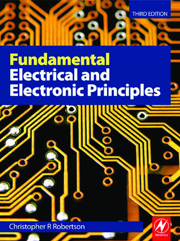
Fundamental Electricaland ElectronicPrinciplesThird EditionChristopher R RobertsonAMSTERDAM BOSTON HEIDELBERG LONDON NEW YORK OXFORDPARIS SAN DIEGO SAN FRANCISCO SINGAPORE SYDNEY TOKYONewnes is an imprint of Elsevier
Newnes is an imprint of ElsevierLinacre House, Jordan Hill, Oxford OX2 8DP, UK30 Corporate Drive, Suite 400, Burlington, MA 01803, USAFirst published 1993 as Electrical and Electronic Principles 1 by Edward ArnoldSecond edition 2001Third edition 2008Copyright C. R. Robertson 1993, 2001Copyright 2008 Elsevier Ltd. All rights reservedThe right of Christopher R. Robertson to be identified as the author of this work hasbeen asserted in accordance with the Copyright, Designs and Patents Act 1988No part of this publication may be reproduced, stored in a retrieval system ortransmitted in any form or by any means electronic, mechanical, photocopying,recording or otherwise without the prior written permission of the publisherPermissions may be sought directly from Elsevier’s Science & TechnologyRights Department in Oxford, UK: phone ( 44) (0) 1865 843830; fax ( 44) (0)1865 853333; email: permissions@elsevier.com. Alternatively you can submityour request online by visiting the Elsevier web site at http://elsevier.com/locate/permissions, and selecting Obtaining permission to use Elsevier materialNoticeNo responsibility is assumed by the publisher for any injury and/or damage topersons or property as a matter of products liability, negligence or otherwise, or fromany use or operation of any methods, products, instructions or ideas contained in thematerial herein.British Library Cataloguing in Publication DataA catalogue record for this book is available from the British LibraryLibrary of Congress Cataloguing in Publication DataA catalogue record for this book is available from the Library of CongressISBN: 978-0-7506-8737-9For information on all Newnes publications visit ourweb site at http://books.elsevier.comTypeset by Charon Tec Ltd., A Macmillan Company.(www.macmillansolutions.com)Printed and bound in Slovenia080910111210987654321
1 Units .11.2 Standard Form Notation.21.3 ‘Scientific’ Notation .21.4 Conversion of Areas and Volumes.41.5 Graphs.51.6 Basic Electrical Concepts .71.7 Communication.26Summary of Equations .29Assignment Questions .302D.C. Circuits . 312.12.22.32.42.52.62.72.82.92.10Resistors in Series .31Resistors in Parallel .35Potential Divider .40Current Divider .41Series/Parallel Combinations .43Kirchhoff ’s Current Law .48Kirchhoff ’s Voltage Law .49The Wheatstone Bridge Network .55The Wheatstone Bridge Instrument .63The Slidewire Potentiometer .65Summary of Equations .68Assignment Questions .69Suggested Practical Assignments .723Electric Fields and Capacitors . 753.13.23.33.43.53.63.73.83.93.10Coulomb’s Law .75Electric Fields .76Electric Field Strength (E) .78Electric Flux ( ) and Flux Density (D) .79The Charging Process and Potential Gradient .80Capacitance (C) .83Capacitors .84Permittivity of Free Space (ε0) .84Relative Permittivity (εr).84Absolute Permittivity (ε) .85v
ing Capacitor Values.85Capacitors in Parallel .87Capacitors in Series .89Series/Parallel Combinations .92Multiplate Capacitors .95Energy Stored .97Dielectric Strength and Working Voltage .101Capacitor Types .102Summary of Equations .105Assignment Questions .107Suggested Practical Assignment .1104Magnetic Fields and 24.134.144.15Magnetic Materials.111Magnetic Fields .111The Magnetic Circuit .114Magnetic Flux and Flux Density.115Magnetomotive Force (mmf ) .116Magnetic Field Strength .117Permeability of Free Space ( 0) .118Relative Permeability ( r).119Absolute Permeability ( ) .119Magnetisation (B/H) Curve .122Composite Series Magnetic Circuits .126Reluctance (S) .128Comparison of Electrical, Magnetic and Electrostatic Quantities .131Magnetic Hysteresis .132Parallel Magnetic Circuits .134Summary of Equations .135Assignment Questions .136Suggested Practical Assignments .1385Electromagnetism . 1415.15.25.35.45.55.65.75.85.95.105.11Faraday ’s Law of Electromagnetic Induction.141Lenz ’s Law.144Fleming’s Righthand Rule .144EMF Induced in a Single Straight Conductor .147Force on a Current-Carrying Conductor.151The Motor Principle .153Force between Parallel Conductors .156The Moving Coil Meter .158Shunts and Multipliers .162Shunts .162Multipliers .163
225.235.24Figure of Merit and Loading Effect .166The Ohmmeter .170Wattmeter .171Eddy Currents .172Self and Mutual Inductance .174Self-Inductance .175Self-Inductance and Flux Linkages .176Factors Affecting Inductance .179Mutual Inductance.180Relationship between Self- and Mutual-Inductance.182Energy Stored .184The Transformer Principle .186Transformer Voltage and Current Ratios .188Summary of Equations .191Assignment Questions .192Suggested Practical Assignments .1956Alternating Quantities . 6.156.166.17Production of an Alternating Waveform .197Angular Velocity and Frequency .200Standard Expression for an Alternating Quantity .200Average Value.203r.m.s. Value .205Peak Factor .206Form Factor.207Rectifiers .208Half-wave Rectifier .209Full-wave Bridge Rectifier .210Rectifier Moving Coil Meter .212Phase and Phase Angle .213Phasor Representation.216Addition of Alternating Quantities.219The Cathode Ray Oscilloscope .224Operation of the Oscilloscope .226Dual Beam Oscilloscopes .228Summary of Equations .229Assignment Questions .230Suggested Practical Assignments .2327D.C. Machines . 2337.1 Motor/Generator Duality .2337.2 The Generation of d.c. Voltage.2357.3 Construction of d.c. Machines . 2387.4 Classification of Generators .238vii
viiiContents7.57.67.77.87.97.10Separately Excited Generator .239Shunt Generator .240Series Generator .242D. C. Motors .244Shunt Motor .244Series Motor .245Summary of Equations .247Assignment Questions .2488D.C. Transients . 2498.1 Capacitor-Resistor Series Circuit (Charging) .2498.2 Capacitor-Resistor Series Circuit (Discharging) .2538.3 Inductor-Resistor Series Circuit (Connection to Supply) .2568.4 Inductor-Resistor Series Circuit (Disconnection).259Summary of Equations .260Assignment Questions .261Suggested Practical Assignments .2629 Semiconductor Theory and Devices . ic Structure .263Intrinsic (Pure) Semiconductors.264Electron-Hole Pair Generation and Recombination .266Conduction in Intrinsic Semiconductors .267Extrinsic (Impure) Semiconductors .268n-type Semiconductor .268p-type Semiconductor .270The p-n Junction .271The p-n Junction Diode .272Forward-biased Diode .273Reverse-biased Diode .273Diode Characteristics.274The Zener Diode .276Assignment Questions .281Suggested Practical Assignments .282Appendix A: SI Units and Quantities .283Answers to Assignment Questions .285Index.289
PrefaceThis Textbook supersedes the second edition of FundamentalElectrical and Electronic Principles. In response to commentsfrom colleges requesting that the contents more closely match theobjectives of the BTEC unit Electrical and Electronic Principles,some chapters have been removed and some exchanged with thecompanion book Further Electrical and Electronic Principles, ISBN9780750687478. Also, in order to encourage students to use otherreference sources, those chapters that have been totally removedmay be accessed on the website address . The previous edition includedSupplementary Worked Examples at the end of each chapter. Themajority of these have now been included within each chapter asWorked Examples, and those that have been removed may be accessedon the above website.This book continues with the philosophy of the previous editionsin that it may be used as a complete set of course notes for studentsundertaking the study of Electrical and Electronic Principles in thefirst year of a BTEC National Diploma/Certificate course. It alsoprovides coverage for some other courses, including foundation/bridging courses which require the study of Electrical and ElectronicEngineering.Fundamental Electrical and Electronic Principles contains 349illustrations, 112 worked examples, 26 suggested practical assignmentsand 234 assignment questions. The answers to the latter are to be foundtowards the end of the book.The order of the chapters does not necessarily follow the orderset out in any syllabus, but rather follows a logical step-by-stepsequence through the subject matter. Some topic areas may extendbeyond current syllabus requirements, but do so both for the sake ofcompleteness and to encourage those students wishing to extend theirknowledge.Coverage of the second year BTEC National Diploma/Certificateunit, Further Electrical Principles, is found in the third edition of thecompanion book Further Electrical and Electronic Principles.C. RobertsonTonbridgeMarch 2008ix
This page intentionally left blank
IntroductionThe chapters follow a sequence that I consider to be a logicalprogression through the subject matter, and in the main, followthe order of objectives stated in the BTEC unit of Electrical andElectronic Principles. The major exception to this is that the topics ofinstrumentation and measurements do not appear in a specific chapterof that title. Instead, the various instruments and measurement methodsare integrated within those chapters where the relevant theory iscovered.Occasionally a word or phrase will appear in bold blue type, and closeby will be a box with a blue background. These emphasised words orphrases may be ones that are not familiar to students, and within thebox will be an explanation of the words used in the text.Throughout the book, Worked Examples appear as Q questionsin bold type, followed by A answers. In all chapters, AssignmentQuestions are provided for students to solve.The first chapter deals with the basic concepts of electricity; the use ofstandard form and its adaptation to scientific notation; SI and derivedunits; and the plotting of graphs. This chapter is intended to providea means of ensuring that all students on a given course start with thesame background knowledge. Also included in this chapter are notesregarding communication. In particular, emphasis is placed on logicaland thorough presentation of information, etc. in the solution ofAssignment Questions and Practical Assignment reports.xi
This page intentionally left blank
Chapter 1Fundamentals1.1UnitsWherever measurements are performed there is a need for a coherentand practical system of units. In science and engineering theInternational System of units (SI units) form the basis of all units used.There are seven ‘base’ units from which all the other units are derived,called derived units.Table 1.1 The SI base unitsQuantityUnitUnit c currentampereATemperaturekelvinKLuminous intensitycandelacdAmount of substancemolemolA few examples of derived units are shown in Table 1.2, and it is worthnoting that different symbols are used to represent the quantity and itsassociated unit in each case.Table 1.2 Some SI derived PowerPWattWEnergyWJouleJResistanceROhm For a more comprehensive list of SI units see Appendix A at the backof the book.1
2Fundamental Electrical and Electronic Principles1.2 Standard Form NotationStandard form is a method of writing large and small numbers in aform that is more convenient than writing a large number of trailing orleading zeroes.For example the speed of light is approximately 300 000 000 m/s.When written in standard form this figure would appears as3.0 108 m/s, where 108 represents 100 000 000Similarly, if the wavelength of ‘red’ light is approximately0.000 000 767 m, it is more convenient to write it in standard form as7. 67 10 7 m, where 10 7 1 / 10 000 000It should be noted that whenever a ‘multiplying’ factor is required,the base 10 is raised to a positive power. When a ‘dividing’ factor isrequired, a negative power is used. This is illustrated below:10 101100 1021000 103etc.1 / 10 0. 1 10 11 / 100 0.01 10 21 / 1000 0.0001 10 3etc.One restriction that is applied when using standard form is that onlythe first non-zero digit must appear before the decimal point.Thus, 46 500 is written as4.65 10 4 and not as 46 .5 103Similarly, 0.002 69 is written as2. 69 10 3 and not as 26. 9 10 4 or 269 10 51.3 ‘Scientific’ NotationThis notation has the advantage of using the base 10 raised to a powerbut it is not restricted to the placement of the decimal point. It has theadded advantage that the base 10 raised to certain powers have uniquesymbols assigned.For example if a body has a mass m 500 000 g.In standard form this would be written asm 5.0 105 g.Using scientific notation it would appear asm 500 kg (500 kilogram)
Fundamentalswhere the ‘k’ in front of the g for gram represents 103.Not only is the latter notation much neater but it gives a better ‘feel’ tothe meaning and relevance of the quantity.See Table 1.3 for the symbols (prefixes) used to represent the variouspowers of 10. It should be noted that these prefixes are arranged inmultiples of 103. It is also a general rule that the positive powers of10 are represented by capital letters, with the negative powers beingrepresented by lower case (small) letters. The exception to this rule isthe ‘k’ used for kilo.Table 1.3 Unit prefixes used in ‘scientific’ notationMultiplying factorPrefix nameSymbol12teraT9gigaG6megaM310kilok10 3millim 6micro 9nanon 12picop101010101010Worked Example 1.1QWrite the following quantities in a concise form using (a) standard form, and (b) scientific notation(i) 0.000 018 A (ii) 15 000 V (iii) 250 000 000 WA(a)(i) 0.000 018 A 1.8 10 5 A(ii) 15 000 V 1.5 104 V(iii) 250 000 000 W 2.5 108 W(b)(i) 0.000 018 A 18 A(ii) 15 000 V 15 kV(iii) 250 000 000 W 250 MW AnsThe above example illustrates the neatness and convenience of the scientific orengineering notation.Worked Example 1.2QWrite the following quantities in scientific (engineering) notation. (a) 25 10 5 A, (b) 3 104 W,(c) 850 000 J, (d) 0.0016 V.A(a)25 10 5 25 10 10 6 250 10 6 6and since 10 is represented by (micro)3
4Fundamental Electrical and Electronic Principlesthen 25 10 5 A 250 A AnsAlternatively, 25 10 5 25 10 2 10 3 0.25 10 3so 25 10 5 A 0.25 mA Ans(b)3 10 4 3 10 1 10 3 or 300 10 6so 3 10 4 W 0.3 mW or 300 W Ans(c)850 000 850 103 or 0.85 106so 850 000 J 850 kJ or 0.85 MJ Ans(d)0.0016 1.6 10 3so 0.0016 V 1.6 mV Ans1.4 Conversion of Areas and VolumesConsider a square having sides of 1 m as shown in Fig. 1.1. In this caseeach side can also be said to be 100 cm or 1000 mm. Hence the area Aenclosed could be stated as:A 1 1 1 m2or A 100 100 102 102 10 4 cm 2or A 1000 1000 103 103 106 mm 2 .1m1mFig. 1.1From the above it may be seen that1 m 2 10 4 cm 2and that 1 m 2 106 mm 2 .Similarly, if the square had sides of 1 cm the area would beA 1 cm 2 10 2 10 2 10 4 m 2 .Again if the sides were of length 1 mm the area would beA 1 mm 2 10 3 10 3 10 6 m 2 .Thus 1 cm2 10 4 m2 and 1 mm2 10 6 m2.
Fun
Newnes is an imprint of Elsevier Linacre House, Jordan Hill, Oxford OX2 8DP, UK 30 Corporate Drive, Suite 400, Burlington, MA 01803, USA First published 1993 as Electrical and Ele

