Transcription
Starter Kit for Arduinocataloguecatalogue .1Arduino IDE(Integrated Development Environment) . 2Introduction . 2Operation demo . 2Step 1: Install the Arduino Software (IDE) . 2Step 2: Get an Uno R3 and USB cable . 4Step 3: Connect the board . 4Step 4: Open Lesson 1: LED blink . 5Step 5: Select your board . 6Step 6: Select your serial port . 8Step 7: Upload the program . 8Step 8: Result . 9Arduino interface introduction . 9Arduino UNO R3hardware introduction . 10How to add library files . 10Learning materials . 12Ebook .12Language Reference . 13Lessons . 13Lesson 1: LED blink . 13Lesson 2: Button . 17Lesson 3: Active buzzer . 20Lesson 4: Passive buzzer . 22Lesson 5: RGB LED . 24Lesson 6: 1 digit 7 Segment Displays . 27Lesson 7: 4 digit 7 Segment Displays . 30Lesson 8: 74HC595 and Flow Led Experiment . 32Lesson 9: LCD1602 with IIC . 35Lesson 10: Relay module experiment . 37Lesson 11: Tilt Switch . 39Lesson 12: Photoresistor . 42Lesson 13: Flame alarm system . 45Lesson 14: Analog temperature . 47Lesson 15: Soil moisture sensor . 50Lesson 16: DHT11 experiment . 52Lesson 17: Touch Lamp . 55Lesson 18: Ultrasonic Ranging . 58Lesson 19: Sweep . 601
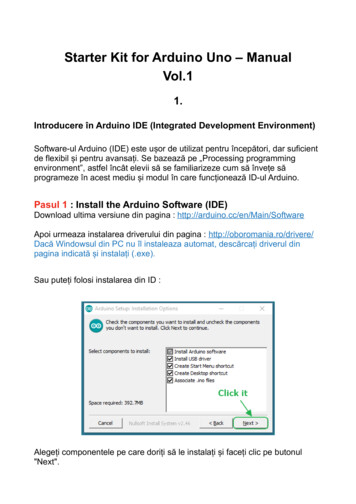
Lesson 20: DC motor . 63Lesson 21: Fun experiment--Color dimmer . 66Lesson 22: Fun experiment--Traffic light . 68Lesson 23: Fun experiment--Intelligent fire . 70Lesson 24: Fun experiment--Theremin . 73Arduino IDE(Integrated Development Environment)IntroductionThe Arduino Software (IDE) is easy-to-use for beginners, yet flexible enough for advancedusers to take advantage of as well. For teachers, it's conveniently based on theProcessing programming environment, so students learning to program in thatenvironment will be familiar with how the Arduino IDE ********************************************* About Elecrow:* We are a leading manufacturer of electronic components for Arduino and Raspberry Pi.* We have a professional engineering team dedicated to providing tutorials and support tohelp you get started.* If you have any technical questions or suggestions, please feel free to contact oursupport staff via email at engle@elecrow.com* We truly hope you enjoy the product, for more great products please visitour company website: https://www.elecrow.comor aliexpress store: https://www.aliexpress.com/store/1306340Operation demoStep 1: Install the Arduino Software (IDE)Download the latest version from this page: http://arduino.cc/en/Main/SoftwareNext, proceed with the installation and please allow the driver installation process.2
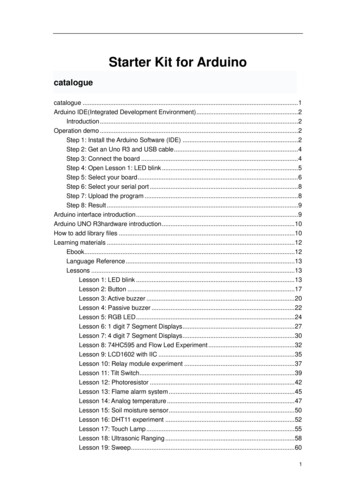
Choose the components to install and click “next” button.Choose the installation directory.3
The process will extract and install all the required files to execute properly the ArduinoSoftware (IDE)Step 2: Get an Uno R3 and USB cableIn this tutorial, you're using an Uno R3. You also need a standard USB cable (A plug toB plug): the kind you would connect to a USB printer, for example.Step 3: Connect the boardThe USB connection with the PC is necessary to program the board and not just topower it up. The Uno and Mega automatically draw power from either the USB or anexternal power supply. Connect the board to your computer using the USB cable. Thegreen power LED (labelled PWR) should go on.4
Step 4: Open Lesson 1: LED blinkOpen the LED blink example sketch: CD For Arduino Demo Code Lesson1-LED bink led blink.5
Step 5: Select your boardYou'll need to select the entry in the Tools Board menu that corresponds to your Arduinoboard.6
Selecting an Arduino/Genuino Uno.7
Step 6: Select your serial portSelect the serial device of the board from the Tools Serial Port menu. This is likely tobe COM3 or higher (COM1 andCOM2 are usually reserved for hardware serial ports). Tofind out, you can disconnect your board and re-open the menu; the entry thatdisappears should be the Arduinoboard. Reconnect the board and select that serialport.Step 7: Upload the programNow, simply click the "Upload" button in the environment. Wait a few seconds - youshould see the RX and TX leds on the board flashing. If the upload is successful, themessage "Done uploading." will appear in the status bar.8
Step 8: ResultA few seconds after the upload finishes, you should see the pin 13 (L) LED on the boardstart to blink (in orange). If it does, congratulations! You've gotten Arduinoup-and-running.Arduino interfaceintroductionABCDEF- Compile- Upload- New- Open- Save- Serial monitor9
Arduino UNO R3hardware introductionHow to add library filesStep 1:10
Add library file: Sketch Include Library Add.ZIP LibraryStep 2:Select your library file compression package on the demo code file, as follows:11
Step3: FinishLearning materialsEbookIntroductionThe E-book about Arduino what we provided for you is carefully selected andcomprehensive, it specially aims at solving the problems when you make projects such assyntax analysis, program optimization and so on.If you have any questions about theprojects what we provided,you can also refer the content of e-books.Path:\For Arduino\Ebook12
Language ence/HomePage/LessonsIntroductionWe will provide you not only the all involved courses about this kit but also to analyze eachcourse. We sincerely hope that you can learn from the first course to the last coursebecause it will lead you start with Arduino step by step, and it also let you jump from anewbieto a higher level for developing your own independent projects.Lesson 1: LED BlinkOverviewThe LED is designed for the beginners of Arduino. Blinking LED experiment is quitesimple and it is the best choice to help you learn I/O pins. On this lesson, we are going toconnect an LED to one of the digital pins.13
SpecificationPin definitionLEDLong pinShort pin- - UNO R3 5VGNDHardware requiredMaterial diagramMaterial nameNumber220/330Ω resistor1LED1USB Cable11UNO R3Breadboard1Jumper wiresSeveral14
Bread board schematicAll the tie points (indicated in the picture) of the different colors are connected together.15
Connection diagramNote:The longest LED of the pin is connected to the digital signal port 13(D13).Compile and uploadTips: Refer to the operation demo (Step4 to Step8).Language referenceTips:click on the following name to jump to the web page.16
If you fail to open, use the Adobe reader to open this italWrite()digitalRead()delay(); (semicolon){} (curly braces) (assign)// (comment)Application effectTurns on an LED on for one second, then off for one second, repeatedly.Lesson 2: ButtonOverview17
Button switches, familiar to most of us, are a switch value (digital value) component.When it's pressed, the circuit is in closed (conducting) state. This example turns on thebuilt-in LED on pin 13 when you press the button.SpecificationSize: 6 x 6 x 5mmTemperature: -30 70 CentigradePin definitionIt is the definition of Button pin:Hardware requiredMaterial diagramMaterial nameNumber1Button10KΩ resistor1USB Cable1UNO R31Breadboard1Jumper wiresSeveral18
Connection diagramConnect three wires to the board. The first two, red and black, connect to the two longvertical rows on the side of the breadboard to provide access to the 5 volt supply andground. The third wire goes from digital pin 2 to one leg of the pushbutton. That same legof the button connects through a pull-down resistor (here 10K ohm) to ground. The otherleg of the button connects to the 5 volt supply.When the pushbutton is open (unpressed) there is no connection between the two legs ofthe pushbutton, so the pin is connected to ground (through the pull-down resistor) and weread a LOW. When the button is closed (pressed), it makes a connection between its twolegs, connecting the pin to 5 volts, so that we read a HIGH.You can also wire this circuit the opposite way, with a pullup resistor keeping the inputHIGH, and going LOW when the button is pressed. If so, the behavior of the sketch will bereversed, with the LED normally on and turning off when you press the button.If you disconnect the digital I/O pin from everything, the LED may blink erratically. This isbecause the input is "floating" - that is, it will randomly return either HIGH or LOW. That'swhy you need a pull-up or pull-down resistor in the circuit.Compile and uploadTips: Refer to the operation demo (Step4 to Step8).19
Language referenceTips:click on the following name to jump to the web page.If you fail to open, use the Adobe reader to open this document.constINPUTApplication effectWhen you press the button, the built-in LED will light up, release is extinguished.Lesson 3: Active BuzzerOverviewThis is an active buzzer experiment.It has an inner vibration source and the direct powersupply can make a sound.SpecificationVoltage: DC 5VMin Sound Output at 10cm: 85dB;Total Size (Pin Not Included): 12 x 9mm/0.47" x 0.35"(D*H)Pin definitionActive BuzzerLong pinShort pin- - UNO R3D5GND20
Hardware requiredMaterial diagramMaterial nameNumberActive buzzer1USB Cable1UNO R31Breadboard1Jumper wiresSeveralConnection diagramNote:The longest active buzzer of the pin is connected to the digital signal port 5 (D5).Compile and uploadTips: Refer to the operation demo (Step4 to Step8).21
Language referenceTips:click on the following name to jump to the web page.If you fail to open, use the Adobe reader to open this document.digitalWrite()pinMode()Application effectWhen the upload process is complete, the buzzer rings.Lesson 4: Passive BuzzerOverviewThis is an Passive buzzer experiment. It cannot be actuated by itself, but external pulse frequencies.Different frequencies produce different sounds. We can use Arduino to code the melody of a song, whichis actually quite fun and simple.SpecificationWorking Voltage: 3V/5VResistance: 16OhmResonance Frequency: 2KHZPin definitionPassive BuzzerLong pinShort pin- - UNO R3D5GND22
Hardware requiredMaterial diagramMaterial nameNumber1Passive buzzerUSB Cable1UNO R31Breadboard1Jumper wiresSeveralConnection diagram23
Compile and uploadTips: Refer to the operation demo (Step4 to Step8).Language referenceTips:click on the following name to jump to the web page.If you fail to open, use the Adobe reader to open this document.#definetone()Application effectWhen the upload process is complete,the buzzer sounds for 2 seconds.Lesson 5: RGB LEDOverviewIn this lesson, you will learn how to use a RGB (Red Green Blue) LED with an Arduino.You will use the analogWrite function of Arduino to control the color of the LED.SpecificationEmitting Light Color: Blue, Red, GreenSize(Approx): 5 x 35mm/ 0.2" x 1.37" (D * L)Forward Voltage: 3.0-3.4VLuminous Intensity: 12000-14000mcd24
Pin definitionIt is the definition of RGB LED pin:RGB LEDRGNDGB- - - - UNO R3D11GNDD10D9Hardware requiredMaterial diagramMaterial nameNumberRGB LED1220Ω/330Ωresistor3USB Cable1UNO R31Breadboard1Jumper wiresSeveral25
Connection diagramNote:The longest pin of the RGB LED is connected to the GND.Compile and uploadTips: Refer to the operation demo (Step4 to Step8).Language referenceTips:click on the following name to jump to the web page.If you fail to open, use the Adobe reader to open this document.analogWrite()#define26
Application effectWhen the program is uploaded, you will see the LED loop emit 7 different colors of light.Lesson 6: 1 Digit 7 Segment DisplaysOverviewThe 7-segment display, also written as “seven segment display”, consists of seven LEDs(hence its name) arranged in a rectangular fashion as shown. Each of the seven LEDs iscalled a segment because when illuminated the segment forms part of a numerical digit(both Decimal and Hex) to be displayed.In general, common anode displays are more popular as many logic circuits can sinkmore current than they can source. Also note that a common cathode display is not adirect replacement in a circuit for a common anode display and vice versa, as it is thesame as connecting the LEDs in reverse, and hence light emission will not take place.One this experiment, we use the 7-segment display (common cathode) to achieve timecounting function.Each segment of the display consists of an LED. So when you use it, you also need usea current-limiting resistor.27
SpecificationNullPin definitionHardware requiredMaterial diagramMaterial nameNumber1 digit LED SegmentDisplays(commoncathode)1220/330Ω resistorUSB Cable1UNO R31Breadboard1Jumper wiresSeveralConnection diagram28
Note:Pay attention to the direction of digital tube.Connection:UNO R3SEGD3- CD4- DD5- ED6- GD7- FD8- AD9- BGND- COMCompile and uploadTips: Refer to the operation demo (Step4 to Step8).29
Language referencearrayApplication effectYou will see the number on the digital tube increased from 0 to 9.Lesson 7: 4 Digit 7 Segment DisplaysOverviewIn this tutorial I will be showing you how to use a 4 digit 7 segment display to achieve time countingfunction.SpecificationNullPin definition30
Hardware requiredMaterial diagramMaterial nameNumber4 digit LED SegmentDisplays(common anode)1220/330Ω resistor8USB Cable1UNO R31Breadboard1Jumper wiresSeveralConnection diagramNote: Pay attention to the direction of digital tube.31
Compile and uploadTips: Refer to the operation demo (Step4 to Step8).Language referenceLongswitch()caseApplication effectThe time counting function, you will see the number of digital tube display increasingly.Lesson 8: 74HC595 and Flow LedExperimentOverviewThe 74HC595 consists of an 8 bit shift register and a storage register with three stateparallel outputs. It converts serial input into parallel output so you can save IO ports of anMCU. You can read and understand the pin diagram of 74HC595 to learn more.In this leeson, you can just use 3 I/O ports to control 8 LED works.SpecificationPlease view 74HC595-datasheet.pdfPath: \Public materials\Datasheet\74HC595-datasheet.pdf32
Pin definitionHardware requiredMaterial diagramMaterial nameNumber74HC5951LED8220/330Ω resistor8USB Cable1UNO R31Breadboard1Jumper wiresSeveral33
Connection diagramCompile and uploadTips: Refer to the operation demo (Step4 to Step8).Language referencebitset();shiftOut();34
Application effectOnly need 3 I/O ports can be used to control the eight LED and you can see 8 LED willflashing like flow water.Lesson 9: LCD1602 with IICOverviewThis lesson will teach you how to use LCD1602 with IIC.SpecificationPlease view LCD1602-datasheet.pdf and PCF8574.pdf.Path:\Datasheet\Pin definitionNull.Hardware requiredMaterial diagramMaterial nameNumberLCD1602 IIC1USB Cable1UNO R31Breadboard1Jumper wiresSeveral35
Connection diagramUNO R3GND 5VSDASCL- - - - LCD1602 IICGNDVCCA4A5Compile and uploadTips: Refer to the operation demo (Step4 to Step8).If you have added the library, skip it.Otherwise, you need to add the LiquidCrystal I2C to the Arduino library file directory,otherwise the compiler does not pass. Please refer to ‘How to add library files’.If the LCD does not display or brightness is not enough, please adjusted thepotentiometer.36
Language ication effectYou will see the LCD display string, while the LCD backlight every 500ms lit once.Lesson 10: Relay Module ExperimentOverviewThis lesson will teach you how to use a button to control a relay experiment.The Delay()function is not used to eliminate jitter and improve the running efficiency of the program.SpecificationNullPin definitionRelay moduleS -- - - UNO R3D8VCCGND37
Hardware requiredMaterial diagramMaterial nameNumberRelay module1Button110KΩ resistor1USB Cable1UNO R31Breadboard1Jumper wiresSeveralConnection diagram38
Compile and uploadTips: Refer to the operation demo (Step4 to Step8).Language referenceTips:click on the following name to jump to the web page.If you fail to open, use the Adobe reader to open this document.constmillis()Application effectWhen the button is pressed, the state of the relay will be changed.Lesson 11: Tilt SwitchOverviewThis tilt switch can easily be used to detect orientation. Inside the can is a ball that makecontact with the pins when the case is upright. Tilt the case over and the balls don’t touch,thus not making a connection.39
SpecificationsPin definitionNopolarity.Hardware requiredMaterial diagramMaterial nameNumber1BallswitchLED1220/330Ω resistor110KΩ resistor1USB Cable1UNO R31Breadboard1Jumper wiresSeveral40
Connection diagramNote:The longest LED of the pin is connected to the digital signal port 11 (D11).Ball switch s pin is not divided into positive and negative polarity.Compile and uploadTips: Refer to the operation demo (Step4 to Step8).41
Language referenceTips:click on the following name to jump to the web page.If you fail to open, use the Adobe reader to open this document.If()elseApplication effectLED light up when you lean or knock on ball switch.Lesson 12: PhotoresistorOverviewA Photoconductive light sensor does not produce electricity but simply changes itsphysical properties when subjected to light energy. The most common type ofphotoconductive device is the Photoresistor which changes its electrical resistance inresponse to changes in the light intensity.SpecificationNull42
Pin definitionHardware requiredMaterial diagramMaterial nameNumberPhotoresistor1USB Cable1UNO R31Breadboard1Jumper wiresSeveral43
Connection diagramCompile and uploadTips: Refer to the operation demo (Step4 to Step8). And open the serial port.Language referenceNull.44
Application effectYou can see the real-time illumination value in the monitor.Lesson 13: Flame Alarm SystemOverviewThe Flame Sensor can be used to detect fire source or other light sources of thewavelength in the range of 760nm - 1100 nm. It is a high speed and high sensitive NPNsilicon phototransistor.This lesson will teach you how to make a Flame alarm system.SpecificationNullPin definitionHardware requiredMaterial diagramMaterial nameNumberActive buzzer145
Flame Sensor110KΩ resistor1USB Cable1UNO R31Breadboard1Jumper wiresSeveralConnection diagramFlame sensorUNO R3Short Pin- 5VLong Pin- A0PassiveBuzzer - D6Note:The short pin of the Flame sensor is connected to 5v.Compile and uploadTips: Refer to the operation demo (Step4 to Step8).Language referenceNullApplication effectWe can simulate a flame environment. Turn on the lighter and then near the flame sensor,you will hear the buzzer sound.46
Lesson 14: Analog TemperatureOverviewThermistors are thermally sensitive resistors whose prime function is to exhibit a large,predictable and precise change in electrical resistance when subjected to a correspondingchange in body temperature.This lesson we will teach you how to read the value of the thermistor.SpecificationModel: MF52-103Insulation Material: CeramicColor: BlackRated Power: 0.05WResistance Value: 10kResistance Tolerance: H (Â 3%)B Value: 3950KPin Pitch: 1.5mm / 0.059"Pin definitionNonpolarHardware requiredMaterial diagramMaterial nameNumber47
1Thermistor10KΩ resistor1USB Cable1UNO R31Breadboard1Jumper wiresSeveral48
Connection diagramNote: Thermistor s pin does not distinguish between positive and negative poles.Compile and uploadTips: Refer to the operation demo (Step4 to Step8). And open the serial port.49
Language referenceserialDECApplication effectAfter uploading the program, open the serial port monitor, you will see a series oftemperature values.Lesson 15: Soil Moisture SensorOverviewThe soil moisture sensor can read the moisture around the soil. So it can be used tomonitor your garden soil moisture and remind you to water the flowers.SpecificationSupply voltage : 3.3V or 5VInput signal: 0 4.2VRated Current : 35mAOutput range and soil moisture :0 300 : Dry300 700 : Damp700 950 : Enough moisturePin definitionNull50
Hardware requiredMaterial diagramMaterial nameNumberDHT111USB Cable1UNO R31Breadboard1Jumper wiresSeveralConnection diagramCompile and uploadTips: Refer to the operation demo (Step4 to Step8). And open the serial port.51
Language referenceNull.Application effectWhen you insert the sensor into the soil, you can see the real-time humidity value of thesoil in the monitor.Lesson 16: DHT11 ExperimentOverviewThis is an experiment on temperature and humidity, you will learn the external library filesto simplify the process.52
SpecificationPlease view DHT11-datasheet.pdf.Path: \Datasheet\ DHT11-datasheet.pdfPin definitionUNO R3GNDD5 5V- - - DHT11GND/’-’DATA/’out’VCC/’ ’Hardware requiredMaterial diagramMaterial nameNumberDHT111USB Cable1UNO R31Breadboard1Jumper wiresSeveral53
Connection diagram54
Compile and uploadTips: Refer to the operation demo (Step4 to Step8).If you have added the library, skip it.Otherwise, you need to add the DHT.h" to the Arduino library file directory, otherwise thecompiler does not pass. Please refer to ‘How to add library files.docx’.Language referenceTips:click on the following name to jump to the web page.If you fail to open, use the Adobe reader to open this document.serialApplication effectOpen the serial port monitor, you will see the value returned by DHT11.Lesson 17: Touch LampOverviewThis is a touch sensor to control the LED lamp experiment, it can control each LED light,but also can achieve the effect of breathing light.SpecificationNull55
Pin definitionTouch SensorGNDVCCSIG- - - UNO R3GND 5VD2Hardware requiredMaterial diagramMaterial nameNumberTouch Sensor1LED3220/330Ω resistor3USB Cable1UNO R31Breadboard1Jumper wiresSeveral56
Connection diagramNote:The longest LED of the pin is connected to the digital signal port.Compile and uploadTips: Refer to the operation demo (Step4 to Step8).57
Language referenceTips:click on the following name to jump to the web page.If you fail to open, use the Adobe reader to open this document.attachInterruptswitch(case)Application effectThrough the touch panel, you can control the LED light.Lesson 18: Ultrasonic RangingOverviewThe HC-SR04 ultrasonic sensor uses sonar to determine distance to an object like bats ordolphins do. It offers excellent non-contact range detection with high accuracy and stablereadings in an easy-to-use package.This is a experimental use of ultrasonic module (HCSR04) test distance. Ultrasonicmodule is generally used in the robot.SpecificationPlease view “HCSR04.pdf”Path: \Datasheet\HCSR04.pdfPin definitionHC SR04VccTrigEcho- - - UNO R3VCCD2D358
Gnd- GNDHardware requiredMaterial diagramMaterial nameNumberHCSR041USB Cable1UNO R31Breadboard1Jumper wiresSeveralConnection diagramConnection:HC SR04VccTrigEchoGnd- - - - UNO R3VCCD2D3GNDCompile and uploadTips: Refer to the operation demo (Step4 to Step8).59
Language referenceTips:click on the following name to jump to the web page.If you fail to open, use the Adobe reader to open this document.delayMicroseconds()Application effectOpen the serial port monitor, and you will see the data returned by the ultrasonic module.button will have the corresponding coding.Lesson 19: SweepOverviewSweeps the shaft of a RC servo motor back and forth across 180 degrees.This example makes use of the Arduino servo library.SpecificationPlease view SG90Servo-datasheet.pdf.Path: \Datasheet\ SG90Servo-datasheet.pdf60
Pin definitionHardware requiredMaterial diagramMaterial nameNumber9g Servo1USB Cable1UNO R31Breadboard1Jumper wiresSeveral61
Connection diagramCompile and uploadTips: Refer to the operation demo (Step4 to Step8).Language referenceNullApplication effectYou will see the servo motor turning 180 degrees back and forth.62
Lesson 20: DC motorOverviewIn this lesson, we will learn how to control the direction and speed of a small-sized DCmotor. The basic problem in using Arduino’s digital pins to control the motor directly is thatit is very difficult to reverse the voltage. So we need to use a L293D chip.This 5V DC motor give the two terminals of the copper sheet one high and one low level,and the motor will rotate. Before proceeding further it is recommended that you read andunderstand the pin diagram of L293D.Now, lets control an DC Motor with a L293D chip and make it so it will go clockwise orcounter clockwise.SpecificationPath: \Datasheet\ L293D-DatasheetPin definitionDC motor:NullL293D:63
Hardware requiredMaterial diagramMaterial nameNumber1Small-sized DC motor1L293DUSB Cable1UNO R31Breadboard1Jumper wiresSeveralPin EN is an enabling pin and works with High level. A stands for input and Y for output.when pin EN is High level, if A is High, Y outputs High level; if A is Low, Y outputs Lowlevel. When pin EN is Low level, the L293D does not work.Because we just needs to driveone motor in this lesson, so use one side of the L293D.Connection diagram64
ConnectionL293DPin1- Pin2- Pin4- Pin5- Pin7- Pin8- Pin16- Uno R35VD10GNDGNDD95V5VCompile and uploadTips: Refer to the operation demo (Step4 to Step8).65
Language referenceNullApplication effectYou can see the DC motor will begin rotating left and right.Lesson 21: Fun Experiment--ColorDimmerWe have learned the RGB LED, it can achieve discoloration. In this lesson, let's do amood light and make it switch with your heart.Hardware requiredMaterial diagramMaterial nameNumber1RGB LED10KΩpotentiometer3USB Cable1UNO R31Breadboard1Jumper wiresSeveral66
Connection diagramConnectionRGB LEDRGB- - - UNO91011Compile and uploadTips: Refer to the operation demo (Step4 to Step8).67
Language referencemap()Application effectYou can rotate the potentiometer to switch the color of the RGB LED, just like colordimmer is cool.Lesson 22: Fun Experiment--Traffic LightIn this lesson, we will use the Arduino to imitate the traffic lights. The lights turn from greento yellow, then turn red and then start all over lights. The time interval follows the trafficsignal standard interval. This item can be used in traffic lights simulation or toys.Hardware requiredMaterial diagramMaterial nameNumberLED(red、yellow、green)3f1 digit LED Segment168
Displays(commoncathode)74HC5951220/330Ω resistor7USB Cable1UNO R31Breadboard1Jumper wiresSeveralConnection diagramCompile and uploadTips: Refer to the operation demo (Step4 to Step8).Language referenceshiftOut();69
Application effectFirst, the LED display counts down from 9s, and the red light in the NS and the green onein the EW light up. Then it counts d
Starter Kit for Arduino . catalogue. . The E-book about Arduino what we provided for you is carefully selected and comprehensive, it specially aims at solv ing the problems when you make projects such as syntax analysis, program o