Transcription
7 Line Differential Protection / 7SD61SIPROTEC 4 7SD61Differential Protection Relay for Two Line EndsLSP2247-afpen.tifFunction overviewFig. 7/10SIPROTEC 4 7SD61differential protection relayDescriptionThe 7SD610 relay is a differential protectionrelay suitable for all types of applicationsand incorporating all those functions required for differential protection of lines,cables and transformers. Transformers andcompensation coils within the differentialprotection zone are protected by means ofintegrated functions, which were previouslyto be found only in transformer differentialprotection. It is also well-suited for complexapplications such as series and parallel compensation of lines and cables.It is designed to provide differential and directional back-up protection for all voltagelevels and types of networks. The relay features high speed and phase-selective shortcircuit measurement. The unit is thus suitable for single-phase and three-phase faultclearance.Digital data communication for differentialcurrent measurement is effected via fiberoptic cables, networks or pilot wires connections, so that the line ends can be quitefar apart. The serial protection data interface(R2R interface) of the relay can flexibly beadapted to the requirements of all existingcommunication media. If the communication method is changed, flexible retrofittingof communication modules to the existingconfiguration is possible.Apart from the main protection function,i.e. the differential protection, the 7SD610has a full range of configurable emergencyand / or back-up protection functions suchas phase and earth overcurrent protectionwith directional elements if voltage transformers are connected. Overload, underand over-voltage/frequency and breakerfailure protection round off the functionalscope of the 7SD610.Protection functions Differential protection for universal usewith power lines and cables on all voltage levels with phase-segregated measurement (87L) Two line ends capability Suitable for transformers in protectedzones (87T) Restricted earth-fault protection (87N) if atransformer is within the protection zone Well-suited for serial compensated lines Two independent differential stages:one stage for sensitive measuring for highresistance faults and one stage for highcurrent faults and fast fault clearance Breaker-failure protection (50BF) Phase and earth overcurrent protectionwith directional element (50, 50N, 51,51N, 67, 67N) Phase-selective intertripping (85) Overload protection (49) Over/undervoltage protection (59/27) Over/underfrequency protection (81O/U) Auto-reclosure single/three-pole (79)Control functions Command and inputs for ctrl. of CBand disconnectors (isolators)Monitoring functions Self-supervision of the relay Trip circuit supervision (74TC) 8 oscillographic fault records CT-secondary current supervision Event logging / fault logging Switching statisticsFront design User-friendly local operation PC front port for convenient relay setting Function keys and 8 LEDs f. local alarmCommunication interfaces 1 serial protection data (R2R) interface Front interface for PC connection System interface IEC 61850 Ethernet IEC 60870-5-103 protocol PROFIBUS-DP, DNP 3.0 andMODBUS Service / modem interface (rear) Time synchronization via IRIG-B,DCF77 or system interfaceFeatures Browser-based commissioning tool Direct connection to digital communication networksSiemens SIP · Edition No. 67/177
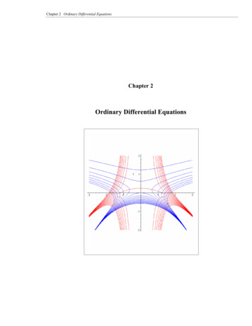
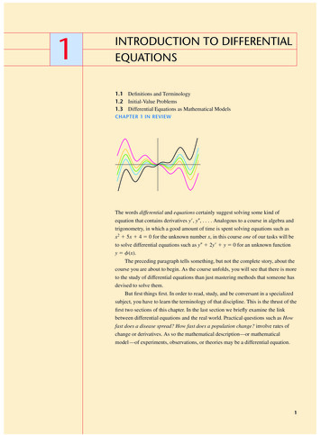
7 Line Differential Protection / 7SD61ApplicationThe 7SD610 relay is a differential protectionrelay suitable for all types of applicationsand incorporating all those functions required for differential protection of lines,cables and transformers.Transformers and compensation coilswithin the differential protection zone areprotected by means of integrated functions,which were previously to be found only intransformer differential protection. It is alsowell-suited for complex applications such asseries and parallel compensation of linesand cables.It is designed to provide protection for allvoltage levels and types of networks; twoline ends may lie within the protection zone.The relay features very high-speed andphase-selective short-circuit measurement.The unit is thus suitable for single andthree-phase fault clearance. The necessaryrestraint current for secure operation is calculated from the current transformer databy the differential protection unit itself.7Digital data communication for differentialcurrent measurement is effected via fiberoptic cables, digital communication networks or pilot wires, so that the line endscan be quite far apart. Thanks to specialproduct characteristics, the relay is particularly suitable for use in conjunction withdigital communication networks.The units measure the delay time in thecommunication network and adaptivelymatch their measurements accordingly. Theunits can be operated through pilot wires ortwisted telephone pairs at typical distancesof 8 km by means of special converters.The serial communication interfaces fordata transmission between the ends are replaceable by virtue of plug-in modules andcan easily be adapted to multi-mode andmono-mode fiber-optic cables and to leasedlines within the communication networks.Secure, selective and sensitive protection oftwo-end lines can now be provided bymeans of these relays.ANSI87LΔI for lines/cables87TΔI for lines / cables withtransformers87NRestricted earth-faultprotection85Phase-selectiveintertrip, remote trip86Lockout function50 50NThree-stage overcurrent51 51N 67 67N protection with directionalelements50HSInstantaneous high-currenttripping (switch-onto-fault)79Single or three-poleauto-reclosure with newadaptive technology49Overload protection50BFBreaker failure protection59 ncyprotection74TCTrip circuit supervisionFig. 7/117/18Siemens SIP · Edition No. 6
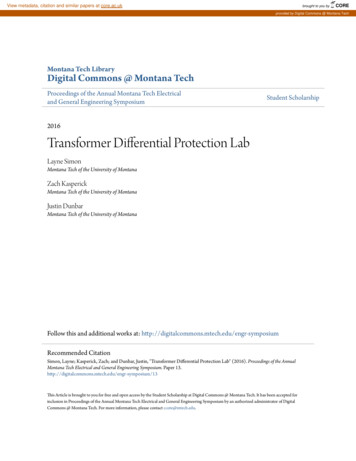
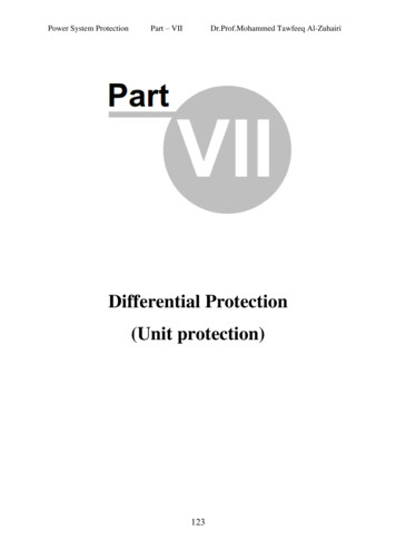
7 Line Differential Protection / 7SD61ApplicationTypical applications employing fiberoptic cables or communication networksFour applications are shown in Fig. 7/12.The 7SD610 differential protection relay isconnected to the current transformers andto the voltage transformers at one end of thecable, although only the currents are required for the differential protection function. The voltage connection improves,among other things, the frequency measurement and allows the measured values andthe fault records to be extended. Direct connection to the other units is effected viamono-mode fiber-optic cables and is thusimmune to interference.Five different modules are available. In thecase of direct connection via fiber-opticcables, data communication is effected at512 kbit/s and the command time of theprotection unit is reduced to 15 ms. Parallelcompensation (for the load currents)is provided within the protection zone ofthe cable. By means of the integrated inrushrestraint, the differential protection relaycan tolerate the surge on switching-on ofthe cable and the compensation reactors,and thus allows sensitive settings to be usedunder load conditions.77SD610 offers many features to reliably andsafely handle data exchange via communication networks.Depending on the bandwidth available acommunication converter for G703-64 kbit/sor X21-64/128/512 kbit/s can be selected. Forhigher communication speed a communication converter with G703-E1 (2,048 kbit/s)or G703-T1 (1,554 kbit/s) is available.Furthermore the 7SD610 supports theIEEE C37.94 interface with 1/2/4 and 8timeslots.The connection to the communicationconverter is effected via a cost-effective820 nm interface with multi-mode fiber.This communication converter convertsthe optical input to electrical signals in accordance to the specified telecommunication interface.The fourth example shows the relays beingconnected via a twisted pilot pair. Dataexchange and transmission is effected viapilot wires of a typical length of 15 km.Here a transformer is in the protected zone.In this application, 7SD610 is set like atransformer differential relay. Vector groupmatching and inrush restraint is providedby the relay.Fig. 7/12Typical applicationsSiemens SIP · Edition No. 67/19
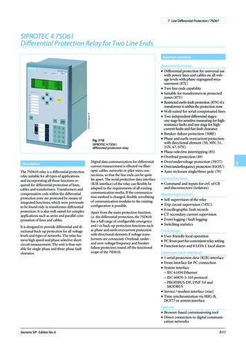
7 Line Differential Protection / 7SD61ConstructionProtection functionsThe 7SD610 is available in a housing widthof 1/3, referred to a 19” module frame system. The height is a uniform 245 mm forflush-mounting housings and 266 mm forsurface-mounting housings.All cables can be connected with or withoutcable ring lugs. Plug-in terminals are available as an option, it is thus possible to employ prefabricated cable harnesses. In thecase of surface mounting on a panel, theconnection terminals are located above andbelow in the form of screw-type terminals.The communication interfaces are locatedon the same sides of the housing. For dimensions, please refer to “Dimension drawings”.Differential protection (ANSI 87L, 87T, 87N)The differential protection function has thefollowing features: LSP2236-afpen.tif Fig. 7/13 7/20 Measurements are performed separately 7 Differential and restraint current arefor each phase; thus the trip sensitivity isindependent of the fault type.An adaptive measurement method withhigh sensitivity for differential fault currents below the rated current offers thedetection of highly resistive faults. Thistrip element uses special filters, whichoffer high security even with high levelDC components in the short-circuit current. The trip time of this stage is about35 ms, the pickup value is about 10 % ofthe rated current.A high-set differential trip stage whichclears differential fault currents higherthan the rated current within 15 ms offersfast tripping time and high-speed faultclearance time. A high-speed chargingcomparison method is employed for thisfunction.When a long line or cable is switched onat one end, transient peaks of the chargecurrent load the line. To avoid a highersetting of the sensitive differential tripstage, this setpoint may be increased for asettable time. This offers greater sensitivityunder normal load conditions.A special feature of the unit isparameterization of the current transformer data. The unit automatically calculates the necessary restraint current bymeans of the previously entered currenttransformer error. The unit thus adaptively matches the working point on thetripping characteristic so that it is no longer necessary for the user to enter characteristic settings.Different current-transformer ratios maybe employed at the ends of the line.A mismatch of 1:8 is permissible.Differential protection tripping can beguarded with overcurrent pickup. In thiscase, pickup of the protection relay is initiated only on simultaneous presence ofdifferential current and overcurrent.Easy to set tripping characteristic. Becausethe relay works adaptively, only the setpoint IDiff (sensitive stage) and IDiff (high-set current differential stage) mustbe set according to the charge current ofthe line/cable. monitored continuously during normaloperation and are displayed as operationalmeasured values.High stability during external faults evenwith different current transformers saturation level. For an external fault, only5 ms of saturation-free time are necessaryto guarantee the stability of the differentialprotection.Single-phase short-circuits within theprotection zone can be cleared using atime delay, whereas multi-phase faults arecleared instantaneously. Because of thisfunction, the unit is optimally suited forapplications in inductively compensatednetworks, where differential current canoccur as a result of charge transfer phenomena on occurrence of a single-phaseearth fault within the protection zone,thus resulting in undesired tripping by thedifferential protection relay. Undesiredtripping of the differential protection canbe suppressed by making use of the provision for introduction of a time delay onoccurrence of single-phase faults.With transformers or compensation coilsin the protection zone, the sensitive response threshold IDiff can be blocked byan inrush detection function. Like intransformer differential protection, itworks with the second harmonic of themeasured current compared with the fundamental component. Blocking is cancelled when an adjustable threshold value ofthe short-circuit current is reached, sothat very high current faults are switchedoff instantaneously.In the case of transformers within theprotection zone, vector group adaptationand matching of different current transformer ratios is carried out within theunit. The interference zero current, whichflows through the earthed winding, iseliminated from the differential currentmeasurement. The 7SD610 thus behaveslike a transformer differential relay whoseends, however, can be quite far apart.A more sensitive protection for transformers within the protection zone isgiven by measurement of the star-pointcurrent on an earthed winding. Thereforethe IE current measurement input has tobe used.Siemens SIP · Edition No. 6
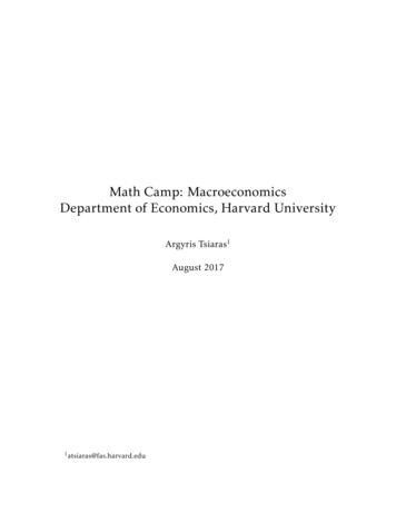
7 Line Differential Protection / 7SD61Protection functionsIf the sum of the phase currents of a winding is compared with the measured starpoint current, a sensitive earth-currentdifferential protection (REF) can be implemented. This function is substantiallymore sensitive than the differential protection during faults to earth in a winding,detecting fault currents as small as 10 % ofthe transformer rated current.Characteristics of differential protectioncommunciation through the remote relayinterfacesThe 7SD610 is ideally adapted for application in communication networks.The data required for measurement of differential currents and numerous other variables are exchanged between the protectionunits in the form of synchronous serial telegrams employing the full duplex mode. Thetelegrams are secured using 32-bit checksums so that transmission errors in a communication network are detected immediately. Moreover, each telegram carries atime stamp accurate to a microsecond, thusallowing measurement and monitoring ofthe continuous transmission delay times. Data communication is immune to elec- tromagnetic interference, since fiber-opticcables are employed in the critical region,e.g. in the relay house or relay room.Monitoring of each individual incomingtelegram and of overall communicationbetween the units, no need of supplementary equipment. The check sum (correctness of the telegram contents), the addressof the neighboring unit and the transmission delay time of the telegram are monitored.Unambiguous identification of each unitis ensured by assignment of a settablecommunication address within a differential protection topology. Only those unitsmutually known to each other can cooperate. Incorrect interconnection of thecommunication links results in blockingof the protection system.Detection of telegrams, which are reflected back to the transmitting unitwithin the communication network.Detection of path switching in a communication network. Automatic restraint ofthe protection function until measurement of the parameters of the new communication link has been completed.Siemens SIP · Edition No. 6 Continuous measurement of the transmission delay time to the remote line end.Taking into account the delay time in differential current measurement and compensation thereof, including monitoringof a settable maximum permissible delaytime of 30 ms. Generation of alarm signals on disturbedcommunication links. Statistical values forthe percentage availability of the communication links per minute and per hourare available as operational measured values. With a GPS high-precision 1-s pulse froma GPS receiver the relays can be syncronized with an absolute, exact time at eachline end. In this way, the delay in the receive and transmit path can be measuredexactly. With this optional feature the relay can used in communication networkswhere this delay times are quite different.Phase-selective intertripand remote trip/indicationsNormally the differential current is calculated for each line end nearly at the sametime. This leads to fast and uniform trippingtimes. Under weak infeed conditions, especially when the differential function iscombined with an overcurrent pickup, aphase-selective intertrip offers a tripping ofboth line ends. 7SD610 has 4 intertrip signals which aretransmitted in high-speed mode (20 ms)to the other terminals. These intertrip signals can also be initiated and transmittedby an external relay via binary inputs. Incases where these signals are not employed for breaker intertripping, otheralternative information can be rapidlytransmitted to the remote end of the line. In addition, four high-speed remote commands are available, which can be introduced either via a binary input or bymeans of an internal event and then rapidly communicated to the other end. Provided that the circuit-breaker auxiliarycontacts are wired to binary inputs at theline ends, the switching status of the circuit-breakers is indicated and evaluated atthe remote ends of the line. Otherwise theswitching status is derived from the measured current.Fig. 7/14Tripping characteristicPossible modes of operationof the differential protection sectionSpecial modes of operation such as the“Commissioning mode” and “Test operation” are advantageous for commissioningand servicing the units. In general, an alarm indication is generated on interruption of the communication links and an attempt is made tore-establish the communication link.The units operate in the emergency mode,provided that these have been parameterized. The complete configuration can also beused in a testing mode. The local end is inan operating mode, which, for example,allows the pickup values to be tested. Thecurrent values received from the remoteend of the line are set to zero, so as toachieve defined test conditions. The remote-end unit ignores the differentialcurrents, which occur as a result of testing, and blocks differential protection andbreaker intertripping. It may optionallyoperate in the backup protection mode. Differential protection is activated in thecommissioning mode. However, test currents injected at one end of the line andwhich generate a differential current donot lead to output of a TRIP commandby the differential protection or to breakerintertripping. All those indications thatwould actually occur in conjunction witha genuine short-circuit are generated anddisplayed. TRIP commands can be issuedby the backup protection.7/217
7 Line Differential Protection / 7SD61Protection functionsThermal overload protection (ANSI 49)A built-in overload protection with a current and thermal alarm stage is provided forthermal protection of cables and transformers.The trip time characteristics are exponentialfunctions according to IEC 60255-8. Thepreload is considered in the trip times foroverloads.An adjustable alarm stage can initiate analarm before tripping is initiated.Overcurrent protection(ANSI 50, 50N, 51, 51N, 67, 67N)7The 7SD610 provides a three-stage overcurrent protection. Two definite-time stagesand one inverse-time stage (IDMT) areavailable, separately for phase currents andfor the earth current. Two operating modes(backup, emergency) are selectable. Twostages e.g. can run in backup mode, whereasthe third stage is configured for emergencyoperation, e.g. during interruption of theprotection communication and/or failure ofthe voltage in the VT secondary circuit. Thesecondary voltage failure can be detected bythe integrated fuse failure monitor or via abinary input from a VT miniature cicuitbreaker (VT m.c.b. trip).Instantaneous high-speed switch-onto-faultovercurrent protection (ANSI 50HS)Instantaneous tripping is possible whenenergizing a faulty line. On large faultcurrents, the high-speed switch-onto-faultovercurrent stage can initiate very fastthree-pole tripping.Circuit-breaker closure onto a faulty lineis also possible provided that the circuitbreaker auxiliary contacts of the remoteend are connected and monitored. If anovercurrent arises on closing of the circuit-breaker at one end of a line (while theother end is energized) the measured current can only be due to a short-circuit. Inthis case, the energizing line end is trippedinstantaneously.In the case of circuit-breaker closure, theauto-reclosure is blocked at both ends ofthe line to prevent a further unsuccessfulclosure onto a short-circuit.If circuit-breaker intertripping to the remote end is activated, intertripping is alsoblocked.Auto-reclosure (ANSI 79)The 7SD610 relay is equipped with anauto-reclose function (AR). The functionincludes several operating modes: 3-pole auto-reclosure for all types ofThe following ANSI/IEC inverse-timecharacteristics are available: Inverse Short inverse Long inverse Moderately inverse Very inverse Extremely inverse Definite inverseIf VTs are connected, separate stages withdirectional measurement are available, twodefinite-time and two inverse-time stages(each for phase and earth). Using the forward pickup indication as a signal to the remote end, a 100 % protection coverage ofthe line can be operated in parallel to thedifferential protection. 7/22faults; different dead times are availabledepending the type of fault1-pole auto-reclosure for 1-phase faults,no reclosing for multi-phase faults1-pole auto-reclosure for 1-phase faultsand for 2-phase faults without earth, noreclosing for multi-phase faults1-pole auto-reclosure for 1-phase and3-pole auto-reclosing for multi-phasefaults1-pole auto-reclosure for 1-phase faultsand 2-phase faults without earth and3-pole auto-reclosure for other faultsMultiple-shot auto-reclosureInteraction with an external device forauto-reclosure via binary inputs and outputsControl of the integrated AR function byexternal protectionAdaptive auto-reclosure. Only one lineend is closed after the dead time. If thefault persists this line end is switched off.Otherwise the other line ends are closedvia a command over the communicationlinks. This avoids stress when heavy faultcurrents are fed from all line ends again.Interaction with an external synchrocheckt 0,140,02( I I p ) 1TpFig. 7/15 Inverse Monitoring of the circuit-breaker auxiliary contactsIn addition to the above-mentioned operating modes, several other operating principles can be employed by means of theintegrated programmable logic (CFC).Integration of auto-reclosure in the feederprotection allows evaluation of the line-sidevoltages. A number of voltage-dependentsupplementary functions are thus available: DLCBy means of dead-line check, reclosure iseffected only when the line is deenergized(prevention of asynchronous breakerclosure). ADTThe adaptive dead time is employed onlyif auto-reclosure at the remote station wassuccessful (reduction of stress on equipment). RDTReduced dead time is employed in conjunction with auto-reclosure where notele-protection method is employed:When faults within the zone extension, butexternal to the protected line, are switchedoff for rapid auto-reclosure (RAR), theRDT function decides on the basis of measurement of the return voltage from theremote station which has not trippedwhether or not to reduce the dead time.Siemens SIP · Edition No. 6
7 Line Differential Protection / 7SD61Protection functionsBreaker failure protection (ANSI 50BF)The 7SD610 relay incorporates a two-stagebreaker failure protection to detect the failure of tripping command execution, forexample, due to a defective circuit-breaker.The current detection logic is phasesegregated and can therefore also be usedin single-pole tripping schemes. If the faultcurrent is not interrupted after a settabletime delay has expired, a retrip commandor a busbar trip command is generated. Thebreaker failure protection can be initiated byall integrated protection functions as well asby external devices via binary input signals.Frequency protection (ANSI 81O/U)Frequency protection can be used for overfrequency and underfrequency protection.Unwanted frequency changes in the network can be detected and the load can beremoved at a specified frequency setting.Frequency protection can be used over awide frequency range (45 to 55, 55 to65 Hz). There are four elements (selectableas overfrequency or underfrequency) andeach element can be delayed separately.Overvoltage protection, undervoltage protection (ANSI 59, 27)A voltage rise can occur on long lines thatare operating at no-load or are only lightlyloaded. The 7SD610 contains a number ofovervoltage measuring elements. Each measuring element is of two-stage design. Thefollowing measuring elements are available:7 Phase-to-earth overvoltage Phase-to-phase overvoltage Zero-sequence overvoltageThe zero-sequence voltage can be connected to the 4th voltage input or be derived from the phase voltages. Positive-sequence overvoltage of the localend or calculated for the remote end ofthe line (compounding). Negative-sequence overvoltageTripping by the overvoltage measuring elements can be effected either at the local circuit-breaker or at the remote station bymeans of a transmitted signal.The 7SD610 is fitted, in addition, with threetwo-stage undervoltage measuringelements: Phase-to-earth undervoltage Phase-to-phase undervoltage Positive-sequence undervoltageThe undervoltage measuring elements canbe blocked by means of a minimum currentcriterion and by means of binary inputs.Siemens SIP · Edition No. 67/23
7 Line Differential Protection / 7SD61Protection functionsMonitoring and supervision functionsThe 7SD610 relay provides comprehensivemonitoring functions covering both hardware and software. Furthermore, the measured values are continuously checked forplausibility. Therefore the current and voltage transformers are also included in thismonitoring system.Current transformer / Monitoring functionsA broken wire between the CTs and relayinputs under load may lead to maloperation of a differential relay if the load current exceeds the differential setpoint. The7SD610 provides fast broken wire supervision which immediatelly blocks all lineends if a broken wire condition is measuredby a local relay. This avoids maloperationdue to broken wire condition. Only thephase where the broken wire is detected isblocked. The other phases remain underdifferential operation.7Fuse failure monitoringIf any measured voltage is not present dueto short-circuit or open circuit in the voltage transformer secondary circuit the distance protection would respond with anunwanted trip due to this loss of voltage.This secondary voltage interruption can bedetected by means of the integrated fusefailure monitor. Immediate blocking ofdistance protection is provided for all typesof secondary voltage failures.Additional measurement supervisionfunctions are Symmetry of voltages and currents Summation of currents and voltagesLockout (ANSI 86)All binary outputs can be stored like LEDsand reset using the LED reset key. The lockout state is also stored in the event of supplyvoltage failure. Reclosure can only be issuedafter the lockout state is reset.Local measured valuesThe measured values are calculated fromthe measured current and voltage signalsalong with the power factor (cos ϕ), thefrequency, the active and reactive power.Measured values are displayed as primaryor secondary values or in percent of thespecific line rated current and voltage. Therelay uses a 20 bit high-resolution AD converter and the analog inputs are factorycalibrated, so a high accuracy is reached.The following values are available for measured-value processing: Currents 3 x IPhase, 3 I0, IE, IE sensitive Voltages 3 x VPhase-Ground, 3 x VPhase-Phase,3 V0,Ven, Symmetrical components I1, I2, V1, V2 Real power P (Watt), reactive powerQ (Var), apparent power S (VA) Power factor PF ( cos ϕ) Frequency f Differential and restraint current perphase Availability of the data connection to theremote line ends per minute and per hour Regarding delay time measuring with theGPS-version the absolute time for transmit and receive path is displayed separately.Limit value monitoring: Limit valuesare monitored by means of the CFC.Commands can be derived from these limitvalue indications.Trip circuit supervision (ANSI 74TC)One or two binary inputs for each circuitbreaker pole can be used for monitoring thecircuit-breaker trip coils including the connecting cables. An alarm signal is issuedwhenever the circuit is interrupted.7/24Siemens SIP · Edition No. 6
7 Line Differential Protection / 7SD61Protection functionsMeasured values at remote line endsEvery two seconds the currents and voltagesare freezed at the same time at all line endsand transmitted via the communicationlink. At a local line end, currents and voltages are thus available with their amountand phases (angle) locally and remotely.This allows checking the whole configuration under load conditions. In addition, thedifferential and restraint currents are alsodisplayed. Important communication measurements, such as delay time or faulty telegrams per minute/hour are also available asmeasurements. These measured values canbe processed with the help of the CFC logiceditor.Special attention has been paid to commissioning. All binary inputs and outputs canbe displayed and activated directly. This cansimplify the wiring check significantly forthe user. The operational and fault eventsand the fault records are clearly arranged.LSP2845.tifCommissioningFig. 7/16Browser-aided commissioning: Phasor diagram7Furthermore, all currents and optional voltages and phases are available via communication link at the local relay and are displayed in the relay, with DIGSI 4 or with theWeb Monitor.The operational and fault events and faultrecords from all line ends share a commontime tagging which allows to compareevents registered in the different line endson a common time base.In addition to the universal DIGSI 4 operating program, the relay contains a WEBserver that can be accessed via a telecommunication link using a browser (e.g. InternetEx
Differential Protection Relay for Two Line Ends The 7SD610 relay is a differential protection relay suitable for all types of applications and incorporating all those functions re-quired for differential protection of lines, cables and transformers. Transformers and compensation coils within the differential protection zone are protected by .