Transcription
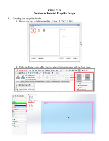
CHEG 3128Solidworks Tutorial: Propeller DesignI.Creating the propeller blade1. Open a new part in Solidworks (File New “Part” OK)2. Under the Features tab, add a reference plane that is coincident with the front plane.
3. Add a second reference plane that is parallel to Plane 1 with 50mm between the two planes. Thiswill be the length of the propeller blade. Isometric View gives a good perspective.4. Sketch a point at the center of Plane 2, then Exit Sketch.
5. Start a new sketch on the top plane6. Sketch a line with the center at the origin. To do this, select Midpoint Line under the Linedropdown menu. Then, select the origin and move the cursor to the right and click to create aline. Make sure the line is horizontal.
7. Using the Smart Dimension tool, set the line length to be 10mm. Smart Dimension will lock inthe dimension so that the length will not change when more elements are added to the design.
8. In the same sketch, draw a spline, starting at the leftmost point of the line and ending at the pointdrawn in the center of Plane 2. Then hit the “Escape” key on your keyboard.Select the spline, then select the bottom point of the spline and drag it down and to the left:
9. In the same sketch, create a second spline; there will be two segments in this spline. First, start atthe rightmost point of the line and end this first segment roughly at the point shown in the picturebelow.Second, end the spline at the point drawn in the center of Plane 2 then hit the “Escape” key. Feelfree to manipulate the shape of this spline as you did with the first spline. Then, Exit Sketch.
10. Under the “Features” tab, select “Extruded Boss/Base.” Set the depth to 2mm, then click on thegreen checkmark to complete the feature.II.Creating the base1. Add a new reference plane. The “First Reference” should be the top plane; set the depth to 2mm.Make sure the new plane is below the top plane; you may have to check the “Flip offset” box.
2. Create a new sketch on the new plane. Sketch a circle whose center is above the origin:3. Draw a second circle that is concentric with the first. Use Smart Dimension to set the diameter ofthe smaller circle to 8.5mm. Also, set the distance between the two circles to 5mm.
4. Select the center of the circles, then drag this point and drop the circles to a point where thelarger circle intersects the entire line. Make sure the circle center is still above the origin; thereshould be a dotted line connecting the two points:5. Under the “Features” tab, select “Extruded Boss/Base.” Direction 1 should be “Blind” and set thedepth to 5mm. Uncheck the “Merge result” box!
6. Create a new sketch on the face of the circle you just extruded. Draw two concentric circles thatare the same diameters as the circles previously drawn.7. Draw lines outlining an inset in the circle. Use the Smart Dimension tool to set the length to6mm:
8. Using the Trim Entities tool, remove the segment of the circle that is connected to the inset (seearrow below), then click the green checkmark to confirm.9. Under the “Features” tab, select “Extruded Boss/Base.” Direction 1 should be “Blind” and set thedepth to 10mm. Make sure the “Merge result” box is checked.
10. Create a new sketch on the face of the inset. Sketch a circle on this face. Using SmartDimension, set the diameter of the circle to 4.10mm, set the center of the circle 5.0mm above thetop of the base, and set the distance from the circle center to the inset edge to 3mm.
11. Under the “Features” tab, select “Extruded Cut.” Set the depth to 5mm. Click the greencheckmark to confirm.
12. Under the “Features” tab, select “Thread” (in the dropdown menu under “Hole Wizard”). TheThread Location is the 4.1mm circle; set the depth to 3.8mm. Under Specifications, set the Typeto “Inch Tap” and the Size to “#10-32”. Click the green checkmark.
III.Complete the model1. Under the “Insert” toolbar, go to Features and then select “Flex.” Select “Twisting” and choosethe blade of the propeller as the Body to Flex.2. Hover the mouse over Trim Plane 1 (green) until the 4-directional arrows appear; click and dragthe plane until it does not touch the cylindrical base.
3. Change the degrees to the desired twist. The picture below has a 30deg twist:4. Add a reference axis to the center of the base; choose the inner cylinder of the base as thereference entity. Click the green checkmark to confirm.
5. Under the “Features” tab, select “Circular Pattern” (may be under the Linear Pattern dropdownmenu). Choose the reference axis that you just made as the Pattern Axis, and choose thepropeller blade as the Body to Pattern. Make sure you are selecting a Body and not a Featureor Face. Check the “Equal Spacing” box, and add 5 instances.Hit the green checkmark:Your design is complete!
Solidworks Tutorial: Propeller Design I. Creating the propeller blade 1. Open a new part in Solidworks (File New “Part” OK) 2. Under the Features tab, add a reference plane that is coincident with the front plane. 3. Add a second reference plane that