Transcription
The open access version with the first 7 sectionsLearning Physical Computingwith Arduinofor the Absolute BeginnerVersion 2.0Harry H. ChengUC Davis Center for Integarted Computing and STEM Education (C-STEM)University of California-Davishttp://c-stem.ucdavis.eduSeptember 5, 2018Copyright c 2018 by Harry H. Cheng, All rights reserved. No part of this publication may be reproducedor distributed in any form or by any means, or stored in a database or retrieval system, without the priorwritten consent of the author, including, but not limited to, in any network or other electronic storage ortransmission, or broadcast for distance learning.1
ContentsPart I: Introduction to Physical Computing1 Introduction1.1 The Board . . . . . . . . . .1.2 The External Circuitry . . .1.3 The Breadboard . . . . . .1.4 The Pins . . . . . . . . . . .1.5 Circuit Schematic Diagrams1.6 Exercises . . . . . . . . . .7.8910131415162 Setting Up and Testing Circuitry with Arduino2.1 Project: Blink through ChDuino . . . . . . . . .2.2 New Concepts . . . . . . . . . . . . . . . . . . . .2.3 Required Components and Materials . . . . . . .2.4 Getting Started . . . . . . . . . . . . . . . . . . .2.5 Building the Circuit . . . . . . . . . . . . . . . .2.6 Opening CSTEM Studio on the Arduino . . . . .2.7 Using the ChDuino GUI . . . . . . . . . . . . . .2.7.1 Find and Manage Arduino Boards . . . .2.8 Scan Arduino Board via USB . . . . . . . . . . .2.9 Scan Arduino Board via Bluetooth . . . . . . . .2.10 Connect and Control an Arduino Board . . . . .2.11 Updating Firmware for the Arduino . . . . . . .2.12 Using ChDuino to Test Hardward Setup . . . . .2.13 Exercises . . . . . . . . . . . . . . . . . . . . . .1717171717181920202122262628283 Programming Arduino in RoboBlockly and Ch3.1 Project:Blink through RoboBlockly and Ch Programs . .3.2 New Concepts . . . . . . . . . . . . . . . . . . . . . . . . .3.3 Required Components and Materials . . . . . . . . . . . .3.4 Getting Started . . . . . . . . . . . . . . . . . . . . . . . .3.5 Exercises . . . . . . . . . . . . . . . . . . . . . . . . . . .3.6 Accessing the Code in C-STEM Studio . . . . . . . . . . .3.7 Using ChIDE to Run Programs . . . . . . . . . . . . . . .3.8 Writing the Code . . . . . . . . . . . . . . . . . . . . . . .3.9 Using ChIDE to Understand and Troubleshoot Programs3.10 Exercises . . . . . . . . . . . . . . . . . . . . . . . . . . .29292930303434373739434 More Blinking4.1 The Direct Method of Repetition . . . . . . . . . . .4.2 SOS . . . . . . . . . . . . . . . . . . . . . . . . . . .4.3 Alternate Repetition Method Using the While-Loop4.4 Using an Infinite While-Loop . . . . . . . . . . . . .4.5 Debugging Revisited . . . . . . . . . . . . . . . . . .4.6 Multiple LEDs . . . . . . . . . . . . . . . . . . . . .4.7 Exercises . . . . . . . . . . . . . . . . . . . . . . . .44444447484955575 Controlling a Traffic Light with a Push-Button5.1 Project: Traffic Light . . . . . . . . . . . . . . . .5.2 New Concepts . . . . . . . . . . . . . . . . . . . .5.3 Required Components and Materials . . . . . . .5.4 Building the Circuit . . . . . . . . . . . . . . . .5.5 Writing the Code Without Input . . . . . . . . .5.6 Building the Circuit (Part 2) . . . . . . . . . . .5.7 ChDuino Basic Test . . . . . . . . . . . . . . . .5858585858606162.2.
5.85.9Writing the Code for Input . . . . . . . . . . . . . . . . . . . . . . . . . . . . . . . . . . . . .Exercises . . . . . . . . . . . . . . . . . . . . . . . . . . . . . . . . . . . . . . . . . . . . . . .6 Using a Potentiometer to Dim an LED6.1 Project: Dimmer . . . . . . . . . . . . .6.2 New Concepts . . . . . . . . . . . . . . .6.3 Required Components and Materials . .6.4 Building the Circuit . . . . . . . . . . .6.5 ChDuino Basic Test . . . . . . . . . . .6.6 Writing the Code . . . . . . . . . . . . .6.7 Exercises . . . . . . . . . . . . . . . . .6365.66666666666869707 Data Acquisition and Plotting Using a Photo-resistor7.1 Project: Graphing Light . . . . . . . . . . . . . . . . . .7.2 New Concepts . . . . . . . . . . . . . . . . . . . . . . . .7.3 Required Components and Materials . . . . . . . . . . .7.4 Learning How to Plot Using plotArray.ch . . . . . . . .7.5 Building the Circuit . . . . . . . . . . . . . . . . . . . .7.6 Writing the Code . . . . . . . . . . . . . . . . . . . . . .7.7 Exercises . . . . . . . . . . . . . . . . . . . . . . . . . .71717171717475788 Using Photo-Resistors and PotentiometersRGB LED8.1 Project: Color Mixing Lamp . . . . . . . .8.2 New Concepts . . . . . . . . . . . . . . . . .8.3 Required Components and Materials . . . .8.4 Building the Circuit . . . . . . . . . . . . .8.5 Writing the Code . . . . . . . . . . . . . . .8.6 Exercises . . . . . . . . . . . . . . . . . . .to Change the Brightness and Color of an.Part II: Physical Computing with Robots9 Using the Arduino to Control Linkbot or Mindstorms9.1 Project: Direction Bot . . . . . . . . . . . . . . . . . . .9.2 New Concepts . . . . . . . . . . . . . . . . . . . . . . . .9.3 Required Components and Materials . . . . . . . . . . .9.4 Building the Circuit . . . . . . . . . . . . . . . . . . . .9.5 Writing the Code to Control the Linkbot . . . . . . . .9.6 Stopping a Linkbot or Mindstorms Robot . . . . . . . .9.7 Writing the Code to Control the Mindstorms . . . . . .9.8 Writing the Code to Control Both Robots . . . . . . . .9.9 Exercises . . . . . . . . . . . . . . . . . . . . . . . . . .8080808080848687.8888888889909394959810 Control the Speed and Spin of a Mindstorms or Linkbot10.1 Project: Potentiometer Bot . . . . . . . . . . . . . . . . . .10.2 New Concepts . . . . . . . . . . . . . . . . . . . . . . . . . .10.3 Required Components and Materials . . . . . . . . . . . . .10.4 Building the Circuit . . . . . . . . . . . . . . . . . . . . . .10.5 Writing the Code for Linkbot Speed . . . . . . . . . . . . .10.6 Writing the Code for Linkbot Spin . . . . . . . . . . . . . .10.7 Exercises . . . . . . . . . . . . . . . . . . . . . . . . . . . .with a Potentiometer. . . . . . . . . . . . . . . . . . . . . . . . . . . . . . . . . . . . . . . . . . . . . . . . . . . . . . . . . . . . . . . . . . . . . . . . . . . . . . . . . . . . . . . . . . . .9999999910010110310511 Adding Sensors to Linkbot Using Linkbot Arduino11.1 Project: Linkbot Siren . . . . . . . . . . . . . . . . .11.2 New Concepts . . . . . . . . . . . . . . . . . . . . . .11.3 Connecting to Power and Ground on the Breadboard11.4 Connecting to Bluetooth . . . . . . . . . . . . . . . .11.5 Required Components and Materials . . . . . . . . .11.6 Building the Circuit . . . . . . . . . . . . . . . . . .1061061061061061071083.Pack. . . . . . . . . . . . . . . . . . .
11.7 Writing the Code for Linkbot Siren . . . . . . . . . . . . . . . . . . . . . . . . . . . . . . . . . 10911.8 Exercises . . . . . . . . . . . . . . . . . . . . . . . . . . . . . . . . . . . . . . . . . . . . . . . 110Part III: Advanced Physical Computing12 Reading an Analog Temperature Sensor12.1 Project: Thermostat . . . . . . . . . . .12.2 New Concepts . . . . . . . . . . . . . . .12.3 Required Components and Materials . .12.4 Building the Circuit . . . . . . . . . . .12.5 Writing the Code . . . . . . . . . . . . .12.6 Exercises . . . . . . . . . . . . . . . . .111.11211211211211311612013 Turning a Servo Motor with a Potentiometer13.1 Project: Servo Control . . . . . . . . . . . . . .13.2 New Concepts . . . . . . . . . . . . . . . . . . .13.3 Required Components and Materials . . . . . .13.4 Building the Circuit . . . . . . . . . . . . . . .13.5 Writing the Code . . . . . . . . . . . . . . . . .13.6 Exercises . . . . . . . . . . . . . . . . . . . . .12112112112112112412614 Playing Notes with a Piezo and Photo-resistor14.1 Project: Light Theremin . . . . . . . . . . . . . .14.2 New Concepts . . . . . . . . . . . . . . . . . . . .14.3 Required Components and Materials . . . . . . .14.4 Building the Circuit . . . . . . . . . . . . . . . .14.5 Writing the Code . . . . . . . . . . . . . . . . . .14.6 Exercises . . . . . . . . . . . . . . . . . . . . . .127127127127127129132a Piezo. . . . . . . . . . . . . . . . . . . . . . . . . . . . . . .133133133133133138140.15 Pressing Different Buttons to Play Different15.1 Project: Piano . . . . . . . . . . . . . . . . .15.2 New Concepts . . . . . . . . . . . . . . . . . .15.3 Required Components and Materials . . . . .15.4 Building the Circuit . . . . . . . . . . . . . .15.5 Writing the Code . . . . . . . . . . . . . . . .15.6 Exercises . . . . . . . . . . . . . . . . . . . .Notes. . . . . . . . . . . . . . . . . . .on. . . . . . .16 Data Acquisition and Plotting with Multiple Inputs andand a Potentiometer16.1 Project: 3D Graphing . . . . . . . . . . . . . . . . . . . .16.2 New Concepts . . . . . . . . . . . . . . . . . . . . . . . . .16.3 Required Components and Materials . . . . . . . . . . . .16.4 Building the Circuit . . . . . . . . . . . . . . . . . . . . .16.5 Writing the Code . . . . . . . . . . . . . . . . . . . . . . .16.6 Exercises . . . . . . . . . . . . . . . . . . . . . . . . . . .Outputs Using a Photo-resistor141. . . . . . . . . . . . . . . . . . . . 141. . . . . . . . . . . . . . . . . . . . 141. . . . . . . . . . . . . . . . . . . . 141. . . . . . . . . . . . . . . . . . . . 141. . . . . . . . . . . . . . . . . . . . 144. . . . . . . . . . . . . . . . . . . . 14917 Using Data Acquisition to Verify Ohm’s17.1 Project: Science! . . . . . . . . . . . . .17.2 New Concepts . . . . . . . . . . . . . . .17.3 Required Components and Materials . .17.4 Building the Circuit . . . . . . . . . . .17.5 Writing the Code . . . . . . . . . . . . .17.6 Exercises . . . . . . . . . . . . . . . . .Law. . . . . . . . . . . . . . . . . . .4.150150150150150151155
18 Timing a Program18.1 Project: Timer . . . . . .18.2 New Concepts . . . . . . .18.3 Required Components and18.4 Building the Circuit . . .18.5 Writing the Code . . . . .18.6 Exercises . . . . . . . . .15615615615615615916219 Moving a DC Motor by Pressing a Button19.1 Project: Transistor Switch . . . . . . . . . .19.2 New Concepts . . . . . . . . . . . . . . . . .19.3 Required Components and Materials . . . .19.4 Building the Circuit . . . . . . . . . . . . .19.5 Writing the Code . . . . . . . . . . . . . . .19.6 Exercises . . . . . . . . . . . . . . . . . . .16316316316316316816920 Controlling the Speed and Direction of a DC Motor20.1 Project: Motor Command . . . . . . . . . . . . . . . .20.2 New Concepts . . . . . . . . . . . . . . . . . . . . . . .20.3 Required Components and Materials . . . . . . . . . .20.4 Building the Circuit . . . . . . . . . . . . . . . . . . .20.5 Writing the Code . . . . . . . . . . . . . . . . . . . . .20.6 Exercises . . . . . . . . . . . . . . . . . . . . . . . . .17017017017017017517921 Writing on an LCD Panel21.1 Project: Magic Eight Ball21.2 New Concepts . . . . . . .21.3 Required Components and21.4 Building the Circuit . . .21.5 Writing the Code . . . . .21.6 Exercises . . . . . . . . . . . . . . . . . . .Materials. . . . . . . . . . . . . . . . . . . . . . . . . .Materials. . . . . . . . . . . . . . . .18018018018018118518922 Using a Piezo as a Vibration Sensor22.1 Project: Knock to Unlock . . . . . .22.2 New Concepts . . . . . . . . . . . . .22.3 Required Components and Materials22.4 Building the Circuit . . . . . . . . .22.5 Writing the Code . . . . . . . . . . .22.6 Exercises . . . . . . . . . . . . . . .190190190190190194198. . . . . . . . . . .IDE. . . . .19919920020020320320320420423 Appendix A: Macros, Functions, and Classes23.1 Macros . . . . . . . . . . . . . . . . . . . . . . . . .23.2 Functions in Ch . . . . . . . . . . . . . . . . . . . .23.3 Functions in Ch and Arduino IDE . . . . . . . . .23.4 Classes . . . . . . . . . . . . . . . . . . . . . . . . .23.4.1 The Servo Class in Ch and Arduino IDE . .23.4.2 The LiquidCrystal Class in Ch and Arduino23.4.3 The CPlot Class in Ch . . . . . . . . . . . .23.4.4 The Robot Class in Ch . . . . . . . . . . .24 Appendix B: Differences of Ch, C, and INO code20624.1 Function Definitions and Arduino’s Setup and Loop Functions . . . . . . . . . . . . . . . . . 20624.2 Interfacing with the Arduino IDE . . . . . . . . . . . . . . . . . . . . . . . . . . . . . . . . . . 2095
25 Appendix C: Hardware25.1 Resistor Color Codes .25.2 Using the Multi-Meter25.2.1 Current . . . .25.2.2 Voltage . . . .25.2.3 Resistance . . .21221221321321321426 Appendix D: Troubleshooting21526.1 Enabling Bluetooth on Windows 7 . . . . . . . . . . . . . . . . . . . . . . . . . . . . . . . . . 21526.2 Enabling Bluetooth on Mac OS . . . . . . . . . . . . . . . . . . . . . . . . . . . . . . . . . . . 215Index2176
Part I:Introduction to Physical Computing7
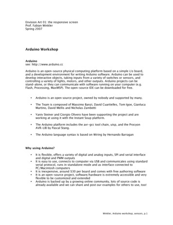
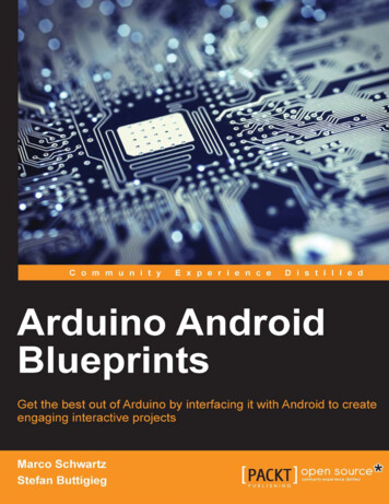
1 IntroductionFor engineers, artists, and students alike, the Arduino single-board microcontroller is one of the most popularof its kind in the world. The rise of the Arduino, and similar boards, has brought the diverse functionalityand power of microcontrollers into the realm of the everyday person by not only displaying near unlimitedusefulness in household tasks, but also by bringing to light the fun and creative side to engineering. Thisdocument will be a walk-through in how to program a microcontroller to interact with electronic componentsusing ChIDE and the Ch programming language.These projects and lessons provide a basic knowledge of how microcontrollers function with inputs (such asswitches, knobs, temperature and light sensors) and outputs (such as LEDs, servos, motors). As an expansionfrom previous C-STEM Center courses involving mathematic computing and robotics programming with theLinkbot, this book gives practical applications for programming and explores some of the inner-workingof robotics programming. This will eventually lead a user to having the required knowledge to use theInput/Output (I/O) capabilities of a microcontroller to create a self-driving, autonomous, vehicle. While aself-driving car is a classic goal for robotics, the possibilities for what a person can do with the power of amicrocontroller is only limited by their creativity. The goal of this book is to provide the user with enoughknowledge to express their creativity through their own personal projects. This book assumes that the userhas the Arduino Uno Starter Kit and Arduino Uno and Pi Sensor Kit , which are available forpurchase from Barobo, Inc. (http://www.barobo.com).(a) Arduino Uno Starter Kit(b) Uno and Pi Sensor Kit8
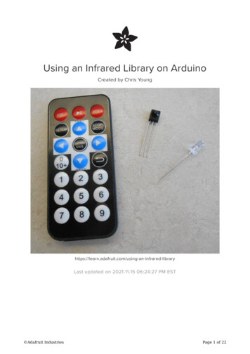
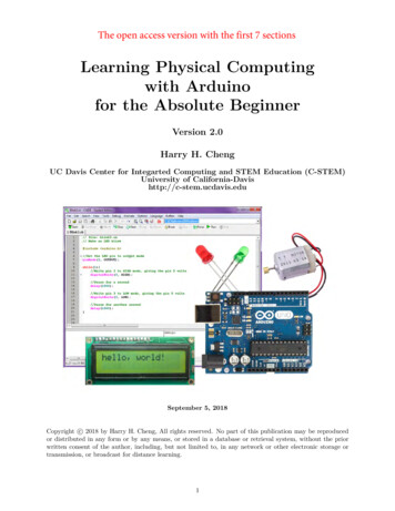
1.1 The BoardFigure 1.2: Arduino Uno Microcontroller BoardThe centerpiece of the Arduino and other similar project boards is the microcontroller. A microcontrolleris a simple computer that is used for specific, simple, tasks that require interfacing with external hardware,like reading information from a sensor or controlling a motor. This is unlike the microprocessor in a typicalcomputer, which can run multiple programs at once and is used for general purposes. Microcontrollers aretypically used for what are called embedded systems. Embedded systems are only programmed once forone task and contain only the electronic and mechanical components required for completing its task. Asimple example would be the air-conditioning system inside of a house. The microcontroller inside of thatlittle box on the wall takes in information from sensors that tell it what the current temperature is, looksat what buttons the homeowner has pushed to set it, and decides whether or not it needs to turn on theair-conditioning unit.Aside from the microcontroller, the boards hold supporting hardware that physically allow the microcontroller to communicate with external devices, such as the computer the programmer is using. Most projectboards will have a series of sockets, called pins, into which wires can be plugged to connect the board toI/O devices, like a button or LED for example. There are also pins for 5 volts, 3.3 volts, ground, and serialdata. There are both digital and analog pins, and a number of the digital pins are PWM capable, whichwill be discussed later in Section 6. The controllers also need to communicate with other computers so thatuser instructions can be received or programs uploaded.Ch code currently supports a variety of Arduino boards, including the Arduino Uno board. Othersupported boards include the Arduino Mega, Leonardo, Nano, and others. The differences between thespectrum of Arduino boards are the processor size and power, the board’s physical size, and the number ofI/O pins. The Uno can be considered the standard board and will work for all of the projects presentedin this book. While other boards will work for projects in this book, they are more often used for specificcircumstances or special applications.9
1.2 The External CircuitryBreadboardsThe circuits required for the projects could be wired directlyto the Arduino but that would be very messy. That is why abreadboard is typically used for building temporary circuits.A breadboard contains a grid of sockets, like those on the Arduino , that can have wires plugged into them. Some pins inthe rows of the breadboard are connected internally so plugging certain pins into certain rows will connect those wires.Breadboards allow for relatively complex circuits to be builtand modified easily for testing and troubleshooting. A morecomplex description will be given in Section 1.4: The Breadboard.SymbolHardwareResistors500As the simplest electrical component, resistors impede currentflow and cause drops in voltage. Resistors are used in filteringelectric signals, controlling power input/output, and protecting other components from power overload. Resistors will beused frequently in this book to protect LEDs from too muchpower. They are color coded to indicate different values of resistance, measured in units called Ohms. Refer to 25.1 in theAppendix for the resistor color-coding system. They have twoleads, or little wires sticking out, that connect to the circuit.Resistors are bidirectional, meaning the leads do not have apositive or negative.CapacitorsA capacitor is an electrical component that stores electricalenergy. Once fully charged, it stops current flow completelyand discharges its stored energy. Capacitors are typically usedto store energy, like a temporary battery, and also for filtering electric signals. Capacitors will be used later in Sections13 and 22 to smooth out the voltage changes across a servo.Many capacitors have a positive and negative side that mustbe plugged in correctly. The side with the stripe on your capacitor is always the negative or ground!Switches/ButtonsAfter years of turning lights on and off, modern society has apretty intuitive understanding of how switches work. A switchor button, when activated by being physically pressed, allowscurrent to flow through a circuit. Switches allow the user/operator to have control and give input to a system. Switchesare how the program knows what the user wants it to do.10
SymbolHardwareTilt SensorA tilt sensor is a special type of switch. It contains a littlemetal ball that, when the sensor is in an upright position, sitson two metal plates which allows current to flow through thesensor. When the sensor is tilted, the little ball rolls off of themetal plates which stops the current and breaks the circuit.PotentiometersAnother way a user can give input to a system is with a potentiometer, which is more commonly known as a knob. A potentiometer is technically a variable resistor. It can produce awide range of resistances which in turn creates various of voltages that can be detected by the computer. While switchescan only be on or off, a potentiometer gives the computer acontinuous range of feedback values. A classic implementationwould be a volume knob on a speaker or stereo. Because theirbasic component is a resistor, potentiometers are bidirectional.DiodesA diode simply allows electrical current to flow in one direction. They must be set up in the correct orientation to workproperly. A diode will be used later in Section 19 to preventthe current generated from a DC motor from damaging thecircuit. Think of the symbol like an arrow that shows thedirection of current toward the end with a marking.LEDsLEDs, or Light Emitting Diodes, have been the primary lightproducing electrical component for the past few decades. Theyare a special type of diode that create light when current ispassed through. They are used widely as indicator lights onelectrical devices, and share the property of controlling currentdirection like a standard diode. They have a longer positiveand shorter negative lead.RGB LEDsRGB (Red Green Blue) LEDs are a type of light emittingdiode that can create any combination of colors by combining3 LEDs into 1. They have 4 pins: red, green, blue, and ground.Applying more voltage to the red pin gives a more red hue,and the same goes for green and blue. Like normal LEDs anddiodes, current only flows in one direction from the color pinsto ground.Photo-resistorsA photo-resistor is a special type of resistor that changes itsresistance when it is exposed to light. Photo-resistors act asvariable resistors, similar to a potentiometer, and will create awide range of voltages depending on how much light it is exposed to. Photo-resistors have many applications as switcheswhere if something blocks a light signal, a photo-resistor candetect it.11
SymbolHardwareTemperature SensorsA temperature sensor will change its resistance based on thetemperature of the surrounding environment. The changingresistance changes the voltage output from the pins of thecomponent, which the single board computer can detect. Thevoltages can be transformed into temperatures with formulas,usually unique to the model of temperature sensor.PiezosA piezo is a buzzer that creates sound with a specific frequencyfor a specific input voltage. Depending on the voltage suppliedit will vibrate, creating sound. It also can be used to detect vibrations. A piezo will be used later in Section 22 for detectingvibrations.LCD ScreensAn LCD, or Liquid Crystal Display, is a way for the program togive the user visual feedback from the single board computer.It can display alpha-numeric characters that can give the userinformation about data or errors and prompt the user to takesome action.Servo MotorsA special type of electric motor that can only rotate in a 180degree range. The exact position the servo will move to isdetermined by the voltage or frequency the single board computer sends to the servo.BJTs (Bipolar Junction Transistor)While a BJT may resemble a temperature sensor, they behavequite differently. BJTs are a type of transistor that have a base,collector, and emitter pin. A transistor can be thought of asan electrical switch. When a voltage is applied to specific leadthen current can flow through the other two leads. Transistorsare used for many applications and are the basis of moderncomputing.MOSFETs (Metal Oxide Semiconductor Field EffectTransistor)MOSFETs are a second type of transistor that work in essentially the same way as a BJT. Even though they are slowerat switching than BJTs due to internal parasitic capacitances,they are much more tolerant to heat and thermal noises, andthus are better suited for high-powered applications. Insteadof a base, collector, and emitter, MOSFETs have a gate, drain,and source.12
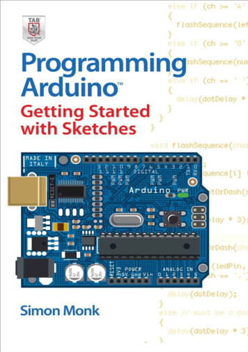
SymbolHardwareH-BridgesAn H-bridge is an integrated chip, or IC, that controls the polarity, positive-to-negative or the negative-to-positive, of thevoltage across a component. This is particularly useful in Section 20 to control the direction a DC motor will spin.DC MotorA DC motor rotates a shaft when a voltage is applied to it.The direction of the shafts rotation depends upon the polarityof the voltage applied.BatteryA battery provides power to an electric circuit or component.In this book batteries are used to power DC motors.Multi-meterA multi-meter is a tool used to measure current, voltages, andresistances of electrical components or circuits. When measuring current, a multi-meter’s symbol is a circle with an ’A’inside, and when measuring voltage the symbol is a circle witha ’V’ inside.1.3 The BreadboardWhen looking at the breadboard with the shorter edge as the horizontal, notice that the two left-most andtwo right-most columns are marked with a ’ ’ and a ’-’. These are the power strips, and each column isconnected internally all the way across the board. Thus, if one wire is plugged into the far upper socket ofa column and another wire is plugged into the far lower socket, then those two wires are connected at thesame voltage. The strips marked ’ ’ are typically where the positive power lead is connected and the stripsmarked ’-’ are where the ground lead is connected. The breakout board plugs one end of a wire into one ofthe columns marked ’ ’ and plug the other end into one of the Arduino pins marked ’5V’, and it does thesame for a ’-’ column and the pin marked ’GND’. Other common names for these columns are rails or buses,so do not be confused when these words are used interchangeably.Look in between the two sets of power strips and see that there are two 5 x 30 socket grids with a trenchin between them. The five sockets in each row are internally connected to each other so that if two wiresare plugged into any of these 5 sockets then those wires are connected at the same voltage. The rows of onegrid are not connected to the rows of the other grid, the trench separates them. Thus for any row, pins a,b, c, d, and e are connected internally and pins f, g, h, i, and j are also connected internally but separatelyfrom a-e.13
a b c d ef g h i 0Row connected internallyColumn connected internally30a b c d ef g h i jFigure 1.3: Breadboard Diagram1.4 The PinsOn either side of the Arduino board is a series of “pins” where wires can be plugged in. Each of these pinshas a dedicated purpose. For example, some are for power, comm
microcontroller is only limited by their creativity. The goal of this book is to provide the user with enough knowledge to express their creativity through their own personal projects. This book assumes that the user has the Arduino Uno Starter Kit and Arduino Uno an