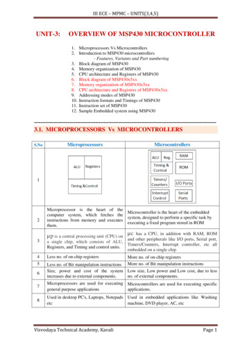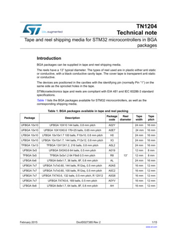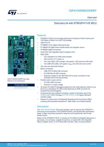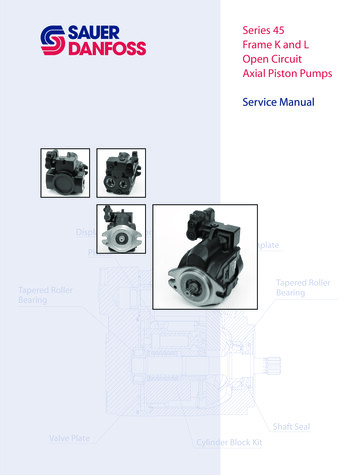
Transcription
Introduction to MicrocontrollersCourses 182.064 & 182.074Vienna University of TechnologyInstitute of Computer EngineeringEmbedded Computing Systems GroupFebruary 26, 2007Version 1.4Günther Gridling, Bettina Weiss
Contents12Microcontroller Basics1.1 Introduction . . . . . .1.2 Frequently Used Terms1.3 Notation . . . . . . . .1.4 Exercises . . . . . . .11678Microcontroller Components2.1 Processor Core . . . . . . . . . .2.1.1 Architecture . . . . . . . .2.1.2 Instruction Set . . . . . .2.1.3 Exercises . . . . . . . . .2.2 Memory . . . . . . . . . . . . . .2.2.1 Volatile Memory . . . . .2.2.2 Non-volatile Memory . . .2.2.3 Accessing Memory . . . .2.2.4 Exercises . . . . . . . . .2.3 Digital I/O . . . . . . . . . . . . .2.3.1 Digital Input . . . . . . .2.3.2 Digital Output . . . . . .2.3.3 Exercises . . . . . . . . .2.4 Analog I/O . . . . . . . . . . . .2.4.1 Digital/Analog Conversion2.4.2 Analog Comparator . . . .2.4.3 Analog/Digital Conversion2.4.4 Exercises . . . . . . . . .2.5 Interrupts . . . . . . . . . . . . .2.5.1 Interrupt Control . . . . .2.5.2 Interrupt Handling . . . .2.5.3 Interrupt Service Routine .2.5.4 Exercises . . . . . . . . .2.6 Timer . . . . . . . . . . . . . . .2.6.1 Counter . . . . . . . . . .2.6.2 Input Capture . . . . . . .2.6.3 Output Compare . . . . .2.6.4 Pulse Width Modulation .2.6.5 Exercises . . . . . . . . .2.7 Other Features . . . . . . . . . . .2.7.1 Watchdog Timer . . . . 060626565666868.i
2.7.22.7.32.7.4345Power Consumption and Sleep . . . . . . . . . . . . . . . . . . . . . . . . .Reset . . . . . . . . . . . . . . . . . . . . . . . . . . . . . . . . . . . . . .Exercises . . . . . . . . . . . . . . . . . . . . . . . . . . . . . . . . . . . .Communication Interfaces3.1 SCI (UART) . . . . . . . . . . . . . .3.2 SPI . . . . . . . . . . . . . . . . . . .3.3 IIC (I2C) . . . . . . . . . . . . . . .3.3.1 Data Transmission . . . . . .3.3.2 Speed Control Through Slave3.3.3 Multi-Master Mode . . . . . .3.3.4 Extended Addresses . . . . .3.4 Exercises . . . . . . . . . . . . . . .Software Development4.1 Development Cycle . . . . . . . . . . . .4.1.1 Design Phase . . . . . . . . . . .4.1.2 Implementation . . . . . . . . . .4.1.3 Testing & Debugging . . . . . . .4.2 Programming . . . . . . . . . . . . . . .4.2.1 Assembly Language Programming4.3 Download . . . . . . . . . . . . . . . . .4.3.1 Programming Interfaces . . . . .4.3.2 Bootloader . . . . . . . . . . . .4.3.3 File Formats . . . . . . . . . . .4.4 Debugging . . . . . . . . . . . . . . . . .4.4.1 No Debugger . . . . . . . . . . .4.4.2 ROM Monitor . . . . . . . . . .4.4.3 Instruction Set Simulator . . . . .4.4.4 In-Circuit Emulator . . . . . . . .4.4.5 Debugging Interfaces . . . . . . .4.5 Exercises . . . . . . . . . . . . . . . . .Hardware5.1 Switch/Button . . . . . . . . . . . . .5.2 Matrix Keypad . . . . . . . . . . . .5.3 Potentiometer . . . . . . . . . . . . .5.4 Phototransistor . . . . . . . . . . . .5.5 Position Encoder . . . . . . . . . . .5.6 LED . . . . . . . . . . . . . . . . . .5.7 Numeric Display . . . . . . . . . . .5.8 Multiplexed Display . . . . . . . . .5.9 Switching Loads . . . . . . . . . . .5.10 Motors . . . . . . . . . . . . . . . . .5.10.1 Basic Principles of Operation5.10.2 DC Motor . . . . . . . . . . .5.10.3 Stepper Motor . . . . . . . .5.11 Exercises . . . . . . . . . . . . . . 35136138140140142146153
A Table of Acronyms155Index159iii
iv
PrefaceThis text has been developed for the introductory courses on microcontrollers taught by the Instituteof Computer Engineering at the Vienna University of Technology. It introduces undergraduate students to the field of microcontrollers – what they are, how they work, how they interface with theirI/O components, and what considerations the programmer has to observe in hardware-based and embedded programming. This text is not intended to teach one particular controller architecture in depth,but should rather give an impression of the many possible architectures and solutions one can comeacross in today’s microcontrollers. We concentrate, however, on small 8-bit controllers and their mostbasic features, since they already offer enough variety to achieve our goals.Since one of our courses is a lab and uses the ATmega16, we tend to use this Atmel microcontrollerin our examples. But we also use other controllers for demonstrations if appropriate.For a few technical terms, we also give their German translations to allow our mainly Germanspeaking students to learn both the English and the German term.Please help us further improve this text by notifying us of errors. If you have any suggestions/wishes like better and/or more thorough explanations, proposals for additional topics, . . . , feelfree to email us at mc-org@tilab.tuwien.ac.at.v
Chapter 1Microcontroller Basics1.1IntroductionEven at a time when Intel presented the first microprocessor with the 4004 there was alrady a demandfor microcontrollers: The contemporary TMS1802 from Texas Instruments, designed for usage in calculators, was by the end of 1971 advertised for applications in cash registers, watches and measuringinstruments. The TMS 1000, which was introduced in 1974, already included RAM, ROM, and I/Oon-chip and can be seen as one of the first microcontrollers, even though it was called a microcomputer. The first controllers to gain really widespread use were the Intel 8048, which was integratedinto PC keyboards, and its successor, the Intel 8051, as well as the 68HCxx series of microcontrollersfrom Motorola.Today, microcontroller production counts are in the billions per year, and the controllers are integrated into many appliances we have grown used to, like household appliances (microwave, washing machine, coffee machine, . . . )telecommunication (mobile phones)automotive industry (fuel injection, ABS, . . . )aerospace industryindustrial automation.But what is this microcontroller we are talking about? What is the difference to a microprocessor?And why do we need microcontrollers in the first place? To answer these questions, let us consider asimple toy project: A heat control system. Assume that we want to periodically read the temperature (analog value, is digitized by sensor; uses 4-bit interface),control heating according to the temperature (turn heater on/off; 1 bit),display the current temperature on a simple 3-digit numeric display (8 3 bits),allow the user to adjust temperature thresholds (buttons; 4 bits), andbe able to configure/upgrade the system over a serial interface.So we design a printed-circuit board (PCB) using Zilog’s Z80 processor. On the board, we put aZ80 CPU, 2 PIOs (parallel I/O; each chip has 16 I/O lines, we need 20), 1 SIO (serial I/O; for communication to the PC), 1 CTC (Timer; for periodical actions), SRAM (for variables), Flash (for program1
2CHAPTER 1. MICROCONTROLLER BASICSmemory), and EEPROM (for constants).1 The resulting board layout is depicted in Figure 1.1; as youcan see, there are a lot of chips on the board, which take up most of the space (euro format, 10 16cm).Figure 1.1: Z80 board layout for 32 I/O pins and Flash, EEPROM, SRAM.Incidentally, we could also solve the problem with the ATmega16 board we use in the Microcontroller lab. In Figure 1.2, you can see the corresponding part of this board superposed on the Z80PCB. The reduction in size is about a factor 5-6, and the ATmega16 board has even more featuresthan the Z80 board (for example an analog converter)! The reason why we do not need much spacefor the ATmega16 board is that all those chips on the Z80 board are integrated into the ATmega16microcontroller, resulting in a significant reduction in PCB size.This example clearly demonstrates the difference between microcontroller and microprocessor: Amicrocontroller is a processor with memory and a whole lot of other components integrated on onechip. The example also illustrates why microcontrollers are useful: The reduction of PCB size savestime, space, and money.The difference between controllers and processors is also obvious from their pinouts. Figure 1.3shows the pinout of the Z80 processor. You see a typical processor pinout, with address pins A0 A15 , data pins D0 -D7 , and some control pins like INT, NMI or HALT. In contrast, the ATmega16has neither address nor data pins. Instead, it has 32 general purpose I/O pins PA0-PA7, PB0-PB7,1We also added a reset button and connectors for the SIO and PIO pins, but leave out the power supply circuitry andthe serial connector to avoid cluttering the layout.
1.1. INTRODUCTION3Figure 1.2: ATmega16 board superposed on the Z80 board.Figure 1.3: Pinouts of the Z80 processor (left) and the ATmega16 controller (right).PC0-PC7, PD0-PD7, which can be used for different functions. For example, PD0 and PD1 can beused as the receive and transmit lines of the built-in serial interface. Apart from the power supply,the only dedicated pins on the ATmega16 are RESET, external crystal/oscillator XTAL1 and XTAL2,and analog voltage reference AREF.Now that we have convinced you that microcontrollers are great, there is the question of whichmicrocontroller to use for a given application. Since costs are important, it is only logical to selectthe cheapest device that matches the application’s needs. As a result, microcontrollers are generallytailored for specific applications, and there is a wide variety of microcontrollers to choose from.The first choice a designer has to make is the controller family – it defines the controller’s archi-
4CHAPTER 1. MICROCONTROLLER BASICStecture. All controllers of a family contain the same processor core and hence are code-compatible,but they differ in the additional components like the number of timers or the amount of memory.There are numerous microcontrollers on the market today, as you can easily confirm by visiting thewebpages of one or two electronics vendors and browsing through their microcontroller stocks. Youwill find that there are many different controller families like 8051, PIC, HC, ARM to name just afew, and that even within a single controller family you may again have a choice of many differentcontrollers.ControllerFlash SRAM EEPROM I/O-PinsA/D Interfaces(KB) 21281283AT90LS234321601285AT90LS85358512512328 UART, 64096538 JTAG, SPI, IICATmega16216102451235JTAG, SPIATmega169161024512538 JTAG, SPI, IICATmega16161024512328 JTAG, SPI, IICATtiny111645 1 InATtiny121646SPIATtiny15L16464 SPIATtiny26212812816 SPIATtiny28L212811 8 InTable 1.1: Comparison of AVR 8-bit controllers (AVR, ATmega, ATtiny).Table 1.12 shows a selection of microcontrollers of Atmel’s AVR family. The one thing all thesecontrollers have in common is their AVR processor core, which contains 32 general purpose registersand executes most instructions within one clock cycle.After the controller family has been selected, the next step is to choose the right controller forthe job (see [Ber02] for a more in-depth discussion on selecting a controller). As you can see inTable 1.1 (which only contains the most basic features of the controllers, namely memory, digital andanalog I/O, and interfaces), the controllers vastly differ in their memory configurations and I/O. Thechosen controller should of course cover the hardware requirements of the application, but it is alsoimportant to estimate the application’s speed and memory requirements and to select a controller thatoffers enough performance. For memory, there is a rule of thumb that states that an application shouldtake up no more than 80% of the controller’s memory – this gives you some buffer for later additions.The rule can probably be extended to all controller resources in general; it always pays to have somereserves in case of unforseen problems or additional features.Of course, for complex applications a before-hand estimation is not easy. Furthermore, in 32bit microcontrollers you generally also include an operating system to support the application and2This table was assembled in 2003. Even then, it was not complete; we have left out all controllers not recommendedfor new designs, plus all variants of one type. Furthermore, we have left out several ATmega controllers. You can find acomplete and up-to-date list on the homepage of Atmel [Atm].
1.1. INTRODUCTION5its development, which increases the performance demands even more. For small 8-bit controllers,however, only the application has to be considered. Here, rough estimations can be made for examplebased on previous and/or similar projects.The basic internal designs of microcontrollers are pretty similar. Figure 1.4 shows the blockdiagram of a typical microcontroller. All components are connected via an internal bus and are allintegrated on one chip. The modules are connected to the outside world via I/O ounter/TimerModuleInternal BusDigital ptController.Figure 1.4: Basic layout of a microcontroller.The following list contains the modules typically found in a microcontroller. You can find a moredetailed description of these components in later sections.Processor Core: The CPU of the controller. It contains the arithmetic logic unit, the control unit,and the registers (stack pointer, program counter, accumulator register, register file, . . . ).Memory: The memory is sometimes split into program memory and data memory. In larger controllers, a DMA controller handles data transfers between peripheral components and the memory.Interrupt Controller: Interrupts are useful for interrupting the normal program flow in case of (important) external or internal events. In conjunction with sleep modes, they help to conservepower.Timer/Counter: Most controllers have at least one and more likely 2-3 Timer/Counters, which canbe used to timestamp events, measure intervals, or count events.Many controllers also contain PWM (pulse width modulation) outputs, which can be used todrive motors or for safe breaking (antilock brake system, ABS). Furthermore the PWM outputcan, in conjunction with an external filter, be used to realize a cheap digital/analog converter.Digital I/O: Parallel digital I/O ports are one of the main features of microcontrollers. The numberof I/O pins varies from 3-4 to over 90, depending on the controller family and the controllertype.
6CHAPTER 1. MICROCONTROLLER BASICSAnalog I/O: Apart from a few small controllers, most microcontrollers have integrated analog/digitalconverters, which differ in the number of channels (2-16) and their resolution (8-12 bits). Theanalog module also generally features an analog comparator. In some cases, the microcontrollerincludes digital/analog converters.Interfaces: Controllers generally have at least one serial interface which can be used to download theprogram and for communication with the development PC in general. Since serial interfacescan also be used to communicate with external peripheral devices, most controllers offer severaland varied interfaces like SPI and SCI.Many microcontrollers also contain integrated bus controllers for the most common (field)busses.IIC and CAN controllers lead the field here. Larger microcontrollers may also contain PCI,USB, or Ethernet interfaces.Watchdog Timer: Since safety-critical systems form a major application area of microcontrollers, itis important to guard against errors in the program and/or the hardware. The watchdog timer isused to reset the controller in case of software “crashes”.Debugging Unit: Some controllers are equipped with additional hardware to allow remote debugging of the chip from the PC. So there is no need to download special debugging software,which has the distinct advantage that erroneous application code cannot overwrite the debugger.Contrary to processors, (smaller) controllers do not contain a MMU (Memory Management Unit),have no or a very simplified instruction pipeline, and have no cache memory, since both costs andthe ability to calculate execution times (some of the embedded systems employing controllers arereal-time systems, like X-by-wire systems in automotive control) are important issues in the microcontroller market.To summarize, a microcontroller is a (stripped-down) processor which is equipped with memory,timers, (parallel) I/O pins and other on-chip peripherals. The driving element behind all this is cost:Integrating all elements on one chip saves space and leads to both lower manufacturing costs andshorter development times. This saves both time and money, which are key factors in embeddedsystems. Additional advantages of the integration are easy upgradability, lower power consumption,and higher reliability, which are also very important aspects in embedded systems. On the downside,using a microcontroller to solve a task in software that could also be solved with a hardware solutionwill not give you the same speed that the hardware solution could achieve. Hence, applications whichrequire very short reaction times might still call for a hardware solution. Most applications, however,and in particular those that require some sort of human interaction (microwave, mobile phone), do notneed such fast reaction times, so for these applications microcontrollers are a good choice.1.2Frequently Used TermsBefore we concentrate on microcontrollers, let us first list a few terms you will frequently encounterin the embedded systems field.Microprocessor: This is a normal CPU (Central Processing Unit) as you can find in a PC. Communication with external devices is achieved via a data bus, hence the chip mainly features dataand address pins as well as a couple of control pins. All peripheral devices (memory, floppycontroller, USB controller, timer, . . . ) are connected to the bus. A microprocessor cannot be
1.3. NOTATION7operated stand-alone, at the very least it requires some memory and an output device to beuseful.Please note that a processor is no controller. Nevertheless, some manufacturers and vendors listtheir controllers under the term “microprocessor”. In this text we use the term processor justfor the processor core (the CPU) of a microcontroller.Microcontroller: A microcontroller already contains all components which allow it to operate standalone, and it has been designed in particular for monitoring and/or control tasks. In consequence, in addition to the processor it includes memory, various interface controllers, one ormore timers, an interrupt controller, and last but definitely not least general purpose I/O pinswhich allow it to directly interface to its environment. Microcontrollers also include bit operations which allow you to change one bit within a byte without touching the other bits.Mixed-Signal Controller: This is a microcontroller which can process both digital and analog signals.Embedded System: A major application area for microcontrollers are embedded systems. In embedded systems, the control unit is integrated into the system3 . As an example, think of a cellphone, where the controller is included in the device. This is easily recognizable as an embedded system. On the other hand, if you use a normal PC in a factory to control an assemblyline, this also meets many of the definitions of an embedded system. The same PC, however,equipped with a normal operating system and used by the night guard to kill time is certainlyno embedded system.Real-Time System: Controllers are frequently used in real-time systems, where the reaction to anevent has to occur within a specified time. This is true for many applications in aerospace,railroad, or automotive areas, e.g., for brake-by-wire in cars.Embedded Processor: This term often occurs in association with embedded systems, and the differences to controllers are often very blurred. In general, the term “embedded processor” is usedfor high-end devices (32 bits), whereas “controller” is traditionally used for low-end devices (4,8, 16 bits). Motorola for example files its 32 bit controllers under the term “32-bit embeddedprocessors”.Digital Signal Processor (DSP): Signal processors are used for applications that need to —no surprise here— process signals. An important area of use are telecommunications, so your mobilephone will probably contain a DSP. Such processors are designed for fast addition and multiplication, which are the key operations for signal processing. Since tasks which call for a signalprocessor may also include control functions, many vendors offer hybrid solutions which combine a controller with a DSP on one chip, like Motorola’s DSP56800.1.3NotationThere are some notational conventions we will follow throughout the text. Most notations will beexplained anyway when they are first used, but here is a short overview:3The exact definition of what constitutes an embedded system is a matter of some dispute. Here is an exampledefinition of an online-encyclopaedia [Wik]:An embedded system is a special-purpose computer system built into a larger device. An embedded systemis typically required to meet very different requirements than a general-purpose personal computer.Other definitions allow the computer to be separate from the controlled device. All definitions have in common that thecomputer/controller is designed and used for a special-purpose and cannot be used for general purpose tasks.
8CHAPTER 1. MICROCONTROLLER BASICS When we talk about the values of digital lines, we generally mean their logical values, 0 or 1.We indicate the complement of a logical value X with X, so 1 0 and 0 1. Hexadecimal values are denoted by a preceding or 0x. Binary values are either given likedecimal values if it is obvious that the value is binary, or they are marked with (·)2 . The notation M[X] is used to indicate a memory access at address X. In our assembler examples, we tend to use general-purpose registers, which are labeled with Rand a number, e.g., R0. The sign means “proportional to”. In a few cases, we will need intervals. We use the standard interval notations, which are [.,.] fora closed interval, [.,.) and (.,.] for half-open intervals, and (.,.) for an open interval. Variablesdenoting intervals will be overlined, e.g. dlatch (0, 1]. The notation dlatch 2 adds the constantto the interval, resulting in (0, 1] 2 (2, 3]. We use k as a generic variable, so do not be surprised if k means different things in differentsections or even in different paragraphs within a section.Furthermore, you should be familiar with the following power prefixes4 nanopicofemtoattozeptoyoctoPrefixmµ, unpfazyPower10 310 610 910 1210 1510 1810 2110 24Table 1.2: Power Prefixes1.4 ExercisesExercise 1.1 What is the difference between a microcontroller and a microprocessor?Exercise 1.2 Why do microcontrollers exist at all? Why not just use a normal processor and add allnecessary peripherals externally?Exercise 1.3 What do you believe are the three biggest fields of application for microcontrollers?Discuss you answers with other students.Exercise 1.4 Visit the homepage of some electronics vendors and compare their stock of microcontrollers.(a) Do all vendors offer the same controller families and manufacturers?4We include the prefixes for 15 and beyond for completeness’ sake – you will probably not encounter them veryoften.
1.4. EXERCISES9(b) Are prices for a particular controller the same? If no, are the price differences significant?(c) Which controller families do you see most often?Exercise 1.5 Name the basic components of a microcontroller. For each component, give an examplewhere it would be useful.Exercise 1.6 What is an embedded system? What is a real-time system? Are these terms synonyms?Is one a subset of the other? Why or why not?Exercise 1.7 Why are there so many microcontrollers? Wouldn’t it be easier for both manufacturersand consumers to have just a few types?Exercise 1.8 Assume that you have a task that requires 18 inputs, 15 outputs, and 2 analog inputs.You also need 512 bytes to store data. Which controllers of Table 1.1 can you use for the application?
10CHAPTER 1. MICROCONTROLLER BASICS
Chapter 2Microcontroller Components2.1Processor CoreThe processor core (CPU) is the main part of any microcontroller. It is often taken from an existingprocessor, e.g. the MC68306 microcontroller from Motorola contains a 68000 CPU. You should already be familiar with the material in this section from other courses, so we will briefly repeat themost important things but will not go into details. An informative book about computer architectureis [HP90] or one of its Instruction to/fromDataMemoryOPStatus(CC) RegZ NOCFlagsALUResultData pathSPCPUFigure 2.1: Basic CPU architecture.A basic CPU architecture is depicted in Figure 2.1. It consists of the data path, which executesinstructions, and of the control unit, which basically tells the data path what to do.11
12CHAPTER 2. MICROCONTROLLER COMPONENTSArithmetic Logic UnitAt the core of the CPU is the arithmetic logic unit (ALU), which is used to perform computations(AND, ADD, INC, . . . ). Several control lines select which operation the ALU should perform on theinput data. The ALU takes two inputs and returns the result of the operation as its output. Source anddestination are taken from registers or from memory. In addition, the ALU stores some informationabout the nature of the result in the status register (also called condition code register):Z (Zero): The result of the operation is zero.N (Negative): The result of the operation is negative, that is, the most significant bit (msb) of theresult is set (1).O (Overflow): The operation produced an overflow, that is, there was a change of sign in a two’scomplement operation.C (Carry): The operation produced a carry.Two’s complementSince computers only use 0 and 1 to represent numbers, the question arose how to representnegative integer numbers. The basic idea here is to invert all bits of a positive integer to get thecorresponding negative integer (this would be the one’s complement). But this method has theslight drawback that zero is represented twice (all bits 0 and all bits 1). Therefore, a better wayis to represent negative numbers by inverting the positive number and adding 1. For 1 and a4-bit representation, this leads to:1 0001 1 1110 1 1111.For zero, we obtain0 0000 0 1111 1 0000,so there is only one representation for zero now. This method of representation is called thetwo’s complement and is used in microcontrollers. With n bits it represents values within[ 2n 1 , 2n 1 1].Register FileThe register file contains the working registers of the CPU. It may either consist of a set of generalpurpose registers (generally 16–32, but there can also be more), each of which can be the source ordestination of an operation, or it consists of some dedicated registers. Dedicated registers are e.g.an accumulator, which is used for arithmetic/logic operations, or an index register, which is used forsome addressing modes.In any case, the CPU can take the operands for the ALU from the file, and it can store the operation’s result back to the register file. Alternatively, operands/result can come from/be stored to thememory. However, memory access is much slower than access to the register file, so it is usually wiseto use the register file if possible.
2.1. PROCESSOR CORE13Example: Use of Status RegisterThe status register is very useful for a number of things, e.g., for adding or subtracting numbersthat exceed the CPU word length. The CPU offers operations which make use of the carry flag,like ADDCa (add with carry). Consider for example the operation
Figure 1.1: Z80 board layout for 32 I/O pins and Flash, EEPROM, SRAM. Incidentally, we could also solve the problem with the ATmega16 board we use in the Microcon-troller lab. In Figure 1.2, you can see the corresponding part of this board superposed on the Z80 PCB. The reduction in size i