Transcription
Introductory MicrocontrollerProgrammingbyPeter AlleyA ThesisSubmitted to the Facultyof theWORCESTER POLYTECHNIC INSTITUTEin partial fulfillment of the requirements for theDegree of Master of ScienceinRobotics EngineeringMay 2011Prof. William MichalsonAdvisorProf. Taskin PadirCommittee memberProf. Susan JarvisCommittee member
AbstractThis text is a treatise on microcontroller programming. It introduces the major peripherals found on most microcontrollers, including the usage of them,focusing on the ATmega644p in the AVR family produced by Atmel. General information and background knowledge on several topics is also presented.These topics include information regarding the hardware of a microcontrollerand assembly code as well as instructions regarding good program structure andcoding practices. Examples with code and discussion are presented throughout.This is intended for hobbyists and students desiring knowledge on programmingmicrocontrollers, and is written at a level that students entering the junior levelcore robotics classes would find useful.
ContentsPrefacei1 What is a Microcontroller?1.1 Micro-processors, -computers, -controllers1.1.1 Microprocessor . . . . . . . . . . .1.1.2 Microcomputer . . . . . . . . . . .1.1.3 Microcontroller . . . . . . . . . . .1.2 Memory Models . . . . . . . . . . . . . . .1.2.1 Von Neumann . . . . . . . . . . .1.2.2 Harvard Architecture . . . . . . .1.2.3 Modified Harvard Architecture . .1.3 The Stack . . . . . . . . . . . . . . . . . .1.4 Conclusion . . . . . . . . . . . . . . . . .111223345672 Datasheets, SFRs and Libraries2.1 Datasheets . . . . . . . . . . . . .2.1.1 Part Name . . . . . . . . .2.1.2 Description and Operation2.1.3 Absolute Maximum Ratings2.1.4 Electrical Characteristics .2.1.5 Physical Characteristics . .2.1.6 Other Information . . . . .2.2 Special Function Registers . . . . .2.2.1 SFRs in Datasheets . . . .2.2.2 Addressing SFRs . . . . . .2.3 Libraries . . . . . . . . . . . . . . .2.3.1 Including libraries . . . . .2.3.2 Commonly used libraries . .2.4 Conclusion . . . . . . . . . . . . .9910101112131314141517181920.3 Hello World213.1 Example: Lighting an LED . . . . . . . . . . . . . . . . . . . . . 223.2 Programming “Hello World” . . . . . . . . . . . . . . . . . . . . 273.3 Digital Input . . . . . . . . . . . . . . . . . . . . . . . . . . . . . 30
3.43.5DIO Operation . . . . . . . . . . . . . . . . . . . . . . . . . . . .Conclusion . . . . . . . . . . . . . . . . . . . . . . . . . . . . . .4 Analog Digital Converter4.1 Terminology . . . . . . . . . . . . . .4.2 Converting methods . . . . . . . . .4.3 Sources of Error . . . . . . . . . . .4.4 Return to the LED example . . . . .4.4.1 The ATmega644p ADC . . .4.4.2 Understanding the ADC . . .4.4.3 Programming with the ADC4.5 Conclusion . . . . . . . . . . . . . .3641.4343444547474851555 Code Styles5.1 Headers and Header Files . . . . . . .5.1.1 #ifndef MY PROGRAM H . . . .5.1.2 Additional Inclusions . . . . . .5.1.3 Macro Definitions . . . . . . .5.1.4 Global Variable Declaration . .5.1.5 Function Prototypes . . . . . .5.2 Commenting . . . . . . . . . . . . . .5.2.1 Documentation Comments . .5.2.2 Non-Documentation Comments5.3 Code reuse: Functions and Libraries .5.3.1 When to use functions . . . . .5.3.2 Variable Scope and Arguments5.3.3 structs . . . . . . . . . . . . .5.3.4 Libraries . . . . . . . . . . . . .5.4 ADC program revisited . . . . . . . .5.5 Conclusion . . . . . . . . . . . . . . .56565657585959595962636363646465696 C Data Structures6.1 Arrays . . . . . . . . . . . . . . . . . . . .6.1.1 Declaring Arrays . . . . . . . . . .6.1.2 Accessing Arrays . . . . . . . . . .6.1.3 Multi-Dimensional Arrays . . . . .6.2 structs . . . . . . . . . . . . . . . . . . .6.2.1 Declaring structs . . . . . . . . .6.2.2 Uses for structs . . . . . . . . . .6.3 Pointers . . . . . . . . . . . . . . . . . . .6.3.1 Pointer Syntax . . . . . . . . . . .6.3.2 Pointers and arrays . . . . . . . . .6.3.3 Pointers and other data structures6.3.4 Pointers in pass by reference . . .6.3.5 Function pointers . . . . . . . . . .6.4 Conclusion . . . . . . . . . . . . . . . . .707070717172727478787979818182
7 Serial Communications7.1 USART and RS232 Serial . . . . . . . . .7.1.1 RS232 . . . . . . . . . . . . . . . .7.1.2 USART . . . . . . . . . . . . . . .7.1.3 USART Communications Example7.2 Serial Peripheral Interface (SPI) . . . . .7.2.1 SPI Bus . . . . . . . . . . . . . . .7.2.2 Operation . . . . . . . . . . . . . .7.2.3 SPI Communications Example . .7.2.4 Daisy-Chaining SPI devices . . . .7.3 Two-Wire Interface (TWI) . . . . . . . .7.3.1 Operation . . . . . . . . . . . . . .7.3.2 Example . . . . . . . . . . . . . . .7.4 Comparing TWI and SPI . . . . . . . . .7.5 Conclusion . . . . . . . . . . . . . . . . .8383838486868787899496969798998 Interrupts and Timers8.1 Interrupts . . . . . . . . . . .8.1.1 How interrupts work .8.1.2 Using Interrupts . . .8.1.3 The Interrupt Process8.2 Program startup assembly . .8.3 Timing . . . . . . . . . . . . .8.3.1 Basic Methods . . . .8.3.2 Using the Timers . . .8.4 Conclusion . . . . . . . . . .1001001001011021051061061091119 External Devices9.1 Motors . . . . . . . . . . . .9.1.1 Linear Drivers . . .9.1.2 PWM Motor Driver9.2 Servos . . . . . . . . . . . .9.3 Sensors . . . . . . . . . . .9.4 Conclusion . . . . . . . . .11211211211511811912110 Real-Time Operating Systems10.1 Preemptive schedulers . . . .10.2 Cooperative schedulers . . . .10.3 Round-Robin example . . . .10.4 Conclusion . . . . . . . . . .12212212312312911 The final example11.1 Problem statement11.2 Design decisions .11.2.1 Control . .11.2.2 Sense . . .130130130131132.
11.2.3 Decision . . . . . . . . . . . . . .11.3 File structure . . . . . . . . . . . . . . .11.3.1 RTOSmain.c . . . . . . . . . . . .11.3.2 RTOSmain.h . . . . . . . . . . . .11.3.3 tasks.h . . . . . . . . . . . . . .11.3.4 tasks.c . . . . . . . . . . . . . .11.3.5 motor.h and motor.c . . . . . .11.3.6 ADC, SPI and USART libraries .11.4 Conclusion . . . . . . . . . . . . . . . .133135135136137137140140141Afterword142A regstructs.h143B Code for final RTOS exampleB.1 RTOSmain.h . . . . . . . . .B.2 RTOSmain.c . . . . . . . . .B.3 tasks.h . . . . . . . . . . . . .B.4 tasks.c . . . . . . . . . . . . .B.5 motor.h . . . . . . . . . . . .B.6 motor.c . . . . . . . . . . . .B.7 ADC.h . . . . . . . . . . . . .B.8 ADC.c . . . . . . . . . . . . .B.9 SPI.h . . . . . . . . . . . . .B.10 SPI.c . . . . . . . . . . . . . .B.11 USART.h . . . . . . . . . . .B.12 USART.c . . . . . . . . . . .174174176178179183185187189190192194196C Setting up and using Eclipse198C.1 Set up Eclipse for use with the AVR . . . . . . . . . . . . . . . . 198C.2 Making a project . . . . . . . . . . . . . . . . . . . . . . . . . . . 200
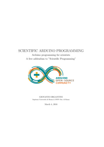
List of Figures1Pin configuration for ATmega644p. . . . . . . . . . . . . . . . . .1.11.21.31.41.5Basic components of a microprocessor. . . . . . . .Basic components of a microcomputer . . . . . . .Block diagram of the von Neumann architecture. .A block diagram of the Harvard architecture. . . .Origin of requested data in LIFO storage (left) and. . . . . . . . . . . . . . . . . . . . . . . . . . . . .FIFO (right).234562.12.22.32.42.5Description section of AND gate datasheet.[18] . . . . . . . . . .Absolute Maximum Ratings section of AND gate datasheet.[18] .Electrical Characteristics section of AND gate datasheet.[18] . .ADCSRA Register Excerpt from ATmega644p datasheet.[11] . .ADPS2:0 Bit field from ADCSRA Register from ATmega644pdatasheet.[11] . . . . . . . . . . . . . . . . . . . . . . . . . . . . .11111215Diagram of a basic controlled system . . . . . . . . . . . . . . . .Excerpt from data sheet for LED part LTL-2F3VEKNT.[16] . . .Excerpt from pp325-326 of datasheet for ATmega644p regardingmaximum sink/source capabilities.[11] . . . . . . . . . . . . . . .Circuit diagram for using the microcontroller as the current source(left) or as a current sink (right). . . . . . . . . . . . . . . . . . .Excerpt from pp325-326 of datasheet for ATmega644p regardingdigital input voltage levels.[11] . . . . . . . . . . . . . . . . . . .Three options for feedback signal. . . . . . . . . . . . . . . . . . .Comparator circuit design from LM193 datasheet.[20] . . . . . .Schematic and calculations for a voltage divider . . . . . . . . . .Logical OR of the output of 2 comparator circuits. From LM193datasheet.[20] . . . . . . . . . . . . . . . . . . . . . . . . . . . . .Circuit diagram of the entire LED control and feedback system. .General Digital I/O schematic from ATmega644p datasheet.[11] .Segment of DIO schematic relating to PORTx register.[11] . . . . .Segment of DIO schematic relating to DDRx register.[11] . . . . .Segment of DIO schematic relating to PINx register.[11] . . . . .Segment of DIO schematic relating to pull-up resistor. . . . . . .Path of PORTxn signal when a pin is set as an output. . . . . . 143.153.16iv152425303233333435373839394041
3.17 Path of PORTxn (heavy, solid line) and input (heavy, dashed line)signals when a pin is set as an input. . . . . . . . . . . . . . . . .4.1424.44.5Aliasing caused by sampling a 7.5Hz signal which is above theNyquist rate of 5Hz. Sampling rate is 10Hz. . . . . . . . . . . . .Complete circuit for LED example using the ADC . . . . . . . .Schematic of the ATmega644p ADC. Found in section 20.2 of thedatasheet.[11] . . . . . . . . . . . . . . . . . . . . . . . . . . . . .Reference voltage selection schematic. Excerpt from figure 4.3. .Signal selection schematic. Excerpt from figure 4.3. . . . . . . . .5051515.1File structure for relative path include. . . . . . . . . . . . . . . .577.17.27.33 devices connected to a microcontroller using SPI. . . . . . . . .The four modes of SPI clock polarity and phase. . . . . . . . . .How to form commands for the LS7366R Quadrature EncoderCounter. [17] . . . . . . . . . . . . . . . . . . . . . . . . . . . . .Bit field descriptions for MDR0 and MDR1. [17] . . . . . . . . . . .States of all four SPI lines during operation to read 16 bit CNTRregister from LS7366R Quadrature Counter. . . . . . . . . . . . .3 devices daisy-chained to a microcontroller using SPI. . . . . . .3 devices connected to a microcontroller using TWI. . . . . . . .8888Differential op amp. . . . . . . . . . . . . . . . . . . . . . . . . .Schematic and equation for completed differential op-amp design.Two modes of H-bridge driving. A) Switches 1 and 4 closed, CWspin of motor. B) Switches 2 and 3 closed, CCW spin. . . . . . .Common servo timings for three angles. . . . . . . . . . . . . . 611711911.1 Range vs Voltage data for the GP2D12 SHARP IR sensor. [19] . 13311.2 Calculating angle formed with the wall based off distance measurements. . . . . . . . . . . . . . . . . . . . . . . . . . . . . . . . 13411.3 File structure of final example showing all files not installed withthe compiler. . . . . . . . . . . . . . . . . . . . . . . . . . . . . . 136C.1 Install New Software window from Eclipse . . . . . . . . . . . . .C.2 Eclipse window with ‘Project Explorer’ and new project buttonmarked. . . . . . . . . . . . . . . . . . . . . . . . . . . . . . . . .C.3 C Project window. . . . . . . . . . . . . . . . . . . . . . . . . . .C.4 Properties window for setting MCU type and clock frequency. . .C.5 Worksheet for setting internal fuses. . . . . . . . . . . . . . . . .200201202203203
List of Tables3.13.2Voltage values for the various feedback possibilities. . . . . . . .Truth table for the PORTxn latch. . . . . . . . . . . . . . . . . . .32387.1Pin assignments for RS232 standard. [5] . . . . . . . . . . . . . .8410.1 Schedule of tasks in round-robin RTOS example. . . . . . . . . . 126
PrefaceWhy this topic?In the spring of 2009, Worcester Polytechnic Institute’s junior level roboticscourses were first offered, with me as one of the teacher’s assistants for thecourses. At the time, I had never worked with microcontrollers before, exceptingthe VEX system used in the lower level WPI robotics classes, which providesa layer of abstraction between the programmer and the actual hardware. Thiswas the first time that many of the students and my self actually had to worryabout special function registers, peripheral initialization and other similar tasks.Over the period of being the TA for these courses multiple times, I learned agreat deal, but also noticed several recurring issues the students seemed toface. In addition to furthering my own knowledge on the care and feeding ofmicrocontrollers, this thesis is an attempt to provide students with a resourceto overcome some of their difficulties, to provide a better understanding of thehardware level operation of a microcontroller, and as instruction into improvingtheir knowledge and code.One problem I noticed, was that many students viewed a microcontrolleras a little black box in which magic happens. By the end of the course theblack box in their imagination may have shrunk slightly and grown a few moreinputs and outputs, but they still did not know what was actually occurring inthe hardware to generate the results they desired and saw. Therefore, one ofmy goals was to provide this understanding both by giving a general overviewof the hardware as well as by examining the schematics for portions of themicrocontroller at a component level and explaining their operation.A second problem is that students appear to have a great aversion to propercommenting and documentation of their code. In many cases it is due to thelaziness and overconfidence of the programmer, however in some cases it is dueto the programmer having never been properly instructed on good practices andthe reasoning behind them. This instruction is something I provide, along withseveral examples of well documented code to model what should be done.Finally, I have noticed that students coding styles lack forethought and design. When handed a problem, they will jump to a conclusion on how to solveone section of it and begin work on that, which causes portions of the solutionto be completed before others are even considered. This leads to disorganized,i
hard to follow code which is difficult to maintain and debug. This text attemptsto demonstrate a method of working through problems stem to stern, and showthat forethought can make the solution simpler and more elegant.Although this text was initially intended for students in the first junior levelrobotics engineering class at WPI (RBE3001), it should prove to be a valuableresource to anyone beginning work with microcontrollers, students and hobbyists alike. This text focuses on the use of the ATmega644p 8-bit microcontrollerproduced by Atmel, though the lessons taught can be applied to any microcontroller, and some lessons to programming in general.OrganizationThis text works through the various peripherals on the ATmega644p in an ordercommensurate with their complexity and usefulness. Interspersed with theseportions are sections devoted to solving the other problems I have noticed overthe years. Chapter 1: What is a Microcontroller?This chapter explains the general components of a microcontroller, viacomparisons with microprocessors and microcomputers. The next stepwas to introduce the common memory models in order to distinguish whatmost people are more familiar with: von Neumann architecture whereprograms and data are stored together such as in desktop computers,from the Harvard architecture commonly used in microcontrollers. TheHarvard memory model separates the program and data memories intoseparate address spaces.The first chapter of the text finishes with an explanation of what thestack is and how it operates. This background knowledge provides a basic understanding of how microcontrollers operate, and is important forunderstanding assembly code. Chapter 2: Datasheets, SFRs and LibrariesChapter 2 is a collection of disparate topics that each deserve discussionprior to beginning to look at code. The section on datasheets disects anexample datasheet and explains the various portions. The special function register section introduces what SFRs are and how to address themon the microcontroller. The final section in the chapter gives a basic understanding of what a library is, and which are most commonly used inprogramming the ATmega644p. Chapter 3: Hello WorldIn this chapter the first peripheral, the digital input and output, is introduced and used in a basic task. This example is examined from avery basic level and demonstrates a good process for solving the problemwithout jumping to conclusions and checking every aspect.ii
Chapter 4: Analog to Digital ConverterContinuing the example from chapter 3, chapter 4 introduces the ADC.After explaining background information on ADCs in general, the exampleusing the ADC on the ATmega644p is presented. Chapter 5: Code Styles As the programs in the examples, and those thatwould be required in using these peripherals, are becoming more complex,chapter 5 takes a break from peripherals and hardware in general to introduce good coding styles. These include how to use and form header files,when to use documentation and non-documentation comments as well asmore information on functions and libraries, this time looking at creatinglibraries rather than using pre-existing ones. The chapter finishes up byreexamining the example from chapter 4, using it to demonstrate properstyles and comments. Chapter 6: C Data Structures Continuing the digression from microcontroller peripherals, chapter 6 presents several data structures that areuseful in programming: arrays, structs and pointers. In addition to discussing what these structures are and the specifics of their usage, severaluses for structs that are not immediately apparent are presented whichaid in making programs cleaner and easier to create. Chapter 7: Serial Communications With this chapter, the text returnsto discussing microcontroller peripherals. After providing backgroundknowledge on serial communications in general, and on each peripheral inquestion, the operations of three types of serial communications are presented with examples. These communications methods are USART andthe RS232 standard, the serial-peripheral interface (SPI) and the two-wireinterface (TWI or I2C). Chapter 8: Interrupts and Timers Chapter 8 concludes the discussionson individual peripherals by introducing hardware interrupts, timers, andhow they can be used in conjunction or separately. Chapter 9: External Devices Up to this point, the text has focused onthe microcontroller and coding styles. This chapter breaks off and looksat the other devices that might need to be attached to a microcontroller:motors, servos, various sorts of sensors, and how to use them. Chapter 10: Real-Time Operating Systems This chapter discusses realtime operating systems (RTOSs) and their uses. It proceeds to present anexample of a basic RTOS that might be used to control a mobile robot,which is implemented in the following chapter. Chapter 11: The Final Example This chapter is dedicated to a single mobile robot example. It begins with a simple problem statement and worksthrough several chains of choices and decisions to be made, culminatingin a functional program.iii
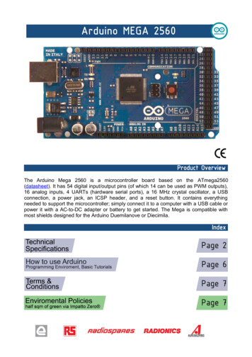
HardwareThis text focuses on the usage of the ATmega644p. This is an 8-bit microcontroller from the AVR family produced by Atmel [1]. There are a varietyto choices for programmers, however the STK500 is a good choice [10]. It is adevelopment board capable of handling a number of difference microcontrollers,provides the hardware for connecting the microcontroller to a computer usingserial via the RS232 standard and provides eight switches and LEDs for usewith basic programs. Figure 1 shows the 40 pins of the ATmega644p with thenames of each pin. Most pins have multiple names as they are used for differenttasks by different peripherals.Figure 1: Pin configuration for ATmega644p.A variety of additional hardware components are introduced, primarily inthe later chapters. These are by no means required to understand and learnfrom this text, and for many readers it would be a better exercise to determinewhat devices best fit their needs, rather than blindly following the examplespresented herein.SoftwareThere are several choices for the software required to develop programs for theATmega644p and download them to the microcontroller. AVR Studio AVR Studio, in version 5 at the time of writing, is a development environment produced by Atmel specifically for the AVR familyof microcontrollers [2]. As it is more dedicated than other IDEs, it hasdebugging and simulation tools that surpass those available elsewhere. Itsiv
primary drawback is that it is specialized and cannot be used to developprograms for microcontrollers outside this family. Eclipse Eclipse is another good choice for IDEs. Although it requires moresetup and configuration than AVR Studio, it is a very extensible environment and there are plugins available for most any programming languageor environment one could need. Instructions for setting up Eclipse for programming the ATmega644p, as well as for creating projects within Eclipseare provided in appendix C. Others While there most certainly are other choices available, these two arethe best. They provide a great number of features useful in development,and are both well supported in the community, with help easily available.Read, learn and enjoyAs you read this text, keep this thought in the back of your mind: this documentis not trying to turn you into an automaton by telling you how to do everythingevery time. It is attempting to demonstrate methods and teach you how tolearn on your own, providing you with the tools to do so. Keep this in mindand the lessons learned within will be useful outside as well.v
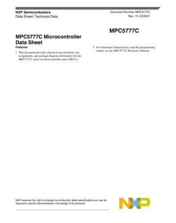
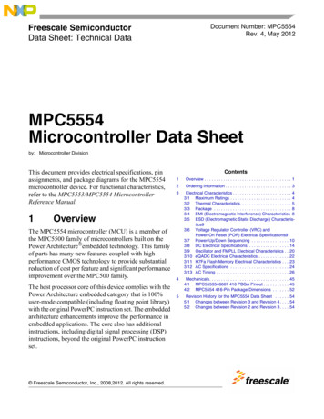
Chapter 1What is a Microcontroller?As time progresses, an increasing number of consumer goods contain microcontrollers. With the current cost of basic microcontrollers as low as 30 cents[6], they are being used as simple solutions to tasks that previously utilizedtransistor-transistor-logic. With the profusion of these devices being used inindustry as well as in hobby electronics the ability to program them can be veryuseful for any project that may be attempted.This text is written to be an introduction to microcontrollers as well as totake a new user from opening the datasheet for the first time through programming a microcontroller and using a variety of peripheral devices. For a moreadvanced user this text will provide suggestions on how to make code morereadable and put forth good coding practices. While this will focus on a single microcontroller, the ATmega644p, the ideas presented are valid for mostmicrocontrollers available today.1.1Micro-processors, -computers, -controllersWhile microprocessors, microcomputers and microcontrollers all share certaincharacteristics and the terms are often used interchangeably, there are certaindistinctions that are used to classify them into separate categories.1.1.1MicroprocessorThe simplest of the three categories is the microprocessor. Also known as aCPU (Central Processing Unit), these devices are generally found at the heartof a much larger system such as a desktop computer and are primarily used asdata processors. They generally consist of an arithmetic logic unit (ALU), aninstruction decoder, a number of registers and digital input/output (DIO) lines(see figure 1.1). Some processors also include memory spaces such as a cache orstack which can be used for more rapid temporary storage and retrieval of datathan having to access system memory. Additionally, the processor must connect1
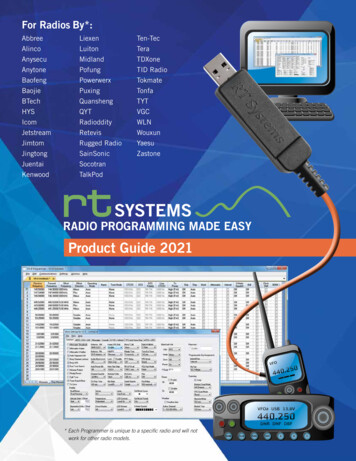
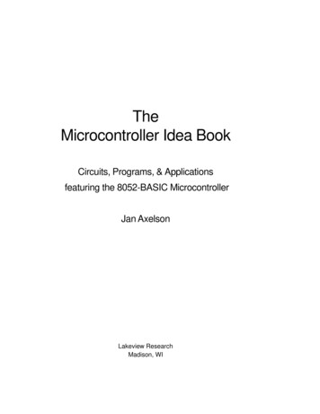
to some form of data bus to access the memory and input/output peripheralsexternal to the processor itself.Figure 1.1: Basic components of a microprocessor.Depending on the memory architecture the microprocessor may have only ahandful of registers such as a program counter for keeping track of the addressof the next instruction and an instruction register for loading and storing thenext instruction; or there may be dozens of registers. These additional registersare known as general purpose registers and store data while it is being used.1.1.2MicrocomputerA microcomputer contains all the components of a computer in a small circuit,though not on a single chip. This term generally applies to laptops and desktopcomputers, however has fallen out of usage for these devices. The componentdevices of a microcomputer consist of a CPU (such as a microprocessor), memoryand/or other storage devices, as well as IO devices (see figure 1.2). Severalexamples of I/O devices include a keyboard, display, network, etc.; but can beany device that the microcomputer uses to collect or distribute information.1.1.3MicrocontrollerA microcontroller is, in some ways, a cross between a microprocessor and amicrocomputer. Like microprocessors, the term microcontroller refers to a single device; however it contains the entire microcomputer on that single chip.Therefore a microcontroller will have a processor, on-board memory as well as avariety of IO devices. While using a microcontroller instead of a microcomputersimplifies the overall design, to accomplish this it sacrifices the flexibility. Amicrocomputer can be configured to have specific quantities of memory or devices attached. Microcontrollers are generally limited to the memory sizes andperipherals that the manufacturers dictate. There are a great many choices in2
Figure 1.2: Basic components of a microcomputermicrocontrollers and their capabilities, however this still can be a limitation insome circumstances.Because microcontrollers are designed more to be standalone data collectionand control devices, rather than for the human interaction or networking tasksthat microcomputers often handle, their standard IO devices differ. Analogdigital converters (ADCs), timers and external interrupts are common peripherals found on microcontrollers, while keyboards, monitors and other devicesused daily to control a personal computer are not.1.21.2.1Memory ModelsVon NeumannThe von Neumann architecture was named after a scientist involved in theManhattan Project and, due to the computational requirements of that project,joined in the development of the EDVAC stored-program computer [12]. Duringthis time he wrote First Draft of a report on the EDVAC, which became thesource of the von Neumann architecture [21].The first computers and computational devices had fixed programs. Theseprograms were built into the machine in various ways and to change the programthe machine often had to be rebuilt. This includes most of the early computerssuch as the ENIAC. These rebuilds could take weeks and used a high percentageof the machine’s time.The von Neumann architecture fixed this problem by storing the programin memory (hence stored-program). This memory block is shared between theprogram storage and data storage, which allows data to be treated as code andvice versa. Furthermore, it allows the use of self-modifying code, which wasuseful in the early days of the architecture to reduce memory use or improve3
performance [21].Figure 1.3 contains a block diagram of the von Neumann architecture. Thisshows the single memory block which both the control unit, the device that readsand interprets the program, and the ALU, where most operations are executed,are connected to. The necessity of communicating with memory external to theCPU leads to a throughput limit known as the von Neumann bottleneck [3].This bottleneck is especially severe in this architecture compared to others dueto the control unit and ALU both needing to read and write to the memory,therefore sharing the limiting resource in the system (memory access time).Figure 1.3: Block diagram of the von Neumann architecture.1.2.2Harvard ArchitectureOne solution to the von Neumann bottleneck is to separate the program memory fr
This text is a treatise on microcontroller programming. It introduces the ma-jor peripherals found on most microcontrollers, including the usage of them, focusing on the ATmega644p in the AVR family produced by Atmel. Gen-eral information and