Transcription
AN4894Application noteEEPROM emulation techniques and software forSTM32 microcontrollersIntroductionEEPROMs (electrically erasable programmable read-only memories) are used for nonvolatile storage of updatable application data, or to retain small amounts of data in the eventof power failure in complex systems. To reduce cost, an external EEPROM can be replacedby on-chip Flash memory, provided that a specific software algorithm is used.This application note describes the software solution (X-CUBE-EEPROM) for substituting astandalone EEPROM by emulating the EEPROM mechanism using the on-chip Flashmemory available on the STM32 Series products listed in Table 1: Applicable products. XCUBE-EEPROM also provides a firmware package including examples showing how toexploit this EEPROM emulation driver (see Section 5: API and application examples).For STM32WB Series products only, an example that maintains a Bluetooth Low-Energyconnection and communication while performing EEPROM operations is provided.The emulation method uses at least two Flash memory pages, between which the EEPROMemulation code swaps data as they become filled. This is transparent to the user. TheEEPROM emulation driver supplied with this application note has the following features: Lightweight implementation and reduced footprint Simple API consisting of a few functions to format, initialize, read and write data, andclean up Flash memory pages At least two Flash memory pages to be used for internal data management Clean-up simplified for the user (background page erase) Wear-leveling algorithm to increase emulated EEPROM cycling capability Robust against asynchronous resets and power failures Optional protection implementation for Flash-memory sharing between cores in multicore STM32 devices (for example STM32WB Series) Maintenance of cache coherency.The EEPROM size to be emulated is flexible and only limited by the Flash memory sizeallocated to that purpose.Table 1. Applicable productsTypeMicrocontrollersDecember 2021SeriesSTM32G0 Series, STM32G4 Series, STM32L4 Series, STM32L4 Series,STM32L5 Series, STM32U5 Series, STM32WB Series, STM32WL SeriesAN4894 Rev 51/40www.st.com1
ContentsContents1General information . . . . . . . . . . . . . . . . . . . . . . . . . . . . . . . . . . . . . . . . . 61.1234Main differences between external and emulated EEPROM . . . . . . . . . 72.1Difference in write access time . . . . . . . . . . . . . . . . . . . . . . . . . . . . . . . . . . 82.2Programming and erase operations . . . . . . . . . . . . . . . . . . . . . . . . . . . . . . 8Implementing EEPROM emulation . . . . . . . . . . . . . . . . . . . . . . . . . . . . . 93.1Principle . . . . . . . . . . . . . . . . . . . . . . . . . . . . . . . . . . . . . . . . . . . . . . . . . . . 93.2Page status valid transitions . . . . . . . . . . . . . . . . . . . . . . . . . . . . . . . . . . . .113.3Page and variable format . . . . . . . . . . . . . . . . . . . . . . . . . . . . . . . . . . . . . 123.4Simple use case . . . . . . . . . . . . . . . . . . . . . . . . . . . . . . . . . . . . . . . . . . . . 153.5Reading data . . . . . . . . . . . . . . . . . . . . . . . . . . . . . . . . . . . . . . . . . . . . . . 17Advanced features . . . . . . . . . . . . . . . . . . . . . . . . . . . . . . . . . . . . . . . . . 184.1Data granularity management . . . . . . . . . . . . . . . . . . . . . . . . . . . . . . . . . 184.2Wear leveling algorithm and Flash page allocation . . . . . . . . . . . . . . . . . 184.3Guard pages . . . . . . . . . . . . . . . . . . . . . . . . . . . . . . . . . . . . . . . . . . . . . . 194.4Cycling capability: EEPROM endurance improvement . . . . . . . . . . . . . . 194.5Computing the required size of Flash for EEPROM emulation . . . . . . . . 214.6EEPROM emulation robustness . . . . . . . . . . . . . . . . . . . . . . . . . . . . . . . . 224.754.6.1Data recovery . . . . . . . . . . . . . . . . . . . . . . . . . . . . . . . . . . . . . . . . . . . . 224.6.2Page header recovery . . . . . . . . . . . . . . . . . . . . . . . . . . . . . . . . . . . . . . 23Real-time considerations . . . . . . . . . . . . . . . . . . . . . . . . . . . . . . . . . . . . . 234.7.1Devices embedding Flash memory with RWW (Read While Write)capability 234.7.2Running the critical processes from the internal RAM . . . . . . . . . . . . . . 244.7.3Dual core considerations . . . . . . . . . . . . . . . . . . . . . . . . . . . . . . . . . . . . 244.8Cleaning up the Flash memory in Interrupt or Polling mode . . . . . . . . . . 254.9Cache coherency maintenance . . . . . . . . . . . . . . . . . . . . . . . . . . . . . . . . 25API and application examples . . . . . . . . . . . . . . . . . . . . . . . . . . . . . . . . 265.12/40Reference documents . . . . . . . . . . . . . . . . . . . . . . . . . . . . . . . . . . . . . . . . 6EEPROM emulation software description . . . . . . . . . . . . . . . . . . . . . . . . 26AN4894 Rev 5
Contents65.1.1Key features . . . . . . . . . . . . . . . . . . . . . . . . . . . . . . . . . . . . . . . . . . . . . . 265.1.2STM32Cube expansion software (X-CUBE-EEPROM) . . . . . . . . . . . . . 275.1.3User defines . . . . . . . . . . . . . . . . . . . . . . . . . . . . . . . . . . . . . . . . . . . . . . 295.1.4User API definition . . . . . . . . . . . . . . . . . . . . . . . . . . . . . . . . . . . . . . . . . 305.2EEPROM emulation memory footprint . . . . . . . . . . . . . . . . . . . . . . . . . . . 315.3EEPROM emulation timing . . . . . . . . . . . . . . . . . . . . . . . . . . . . . . . . . . . . 32Embedded application aspects . . . . . . . . . . . . . . . . . . . . . . . . . . . . . . . 356.1Data retention . . . . . . . . . . . . . . . . . . . . . . . . . . . . . . . . . . . . . . . . . . . . . . 356.2Detecting Flash operations interrupted by a reset on STM32U5 Seriesdevices 356.3Detecting power failures . . . . . . . . . . . . . . . . . . . . . . . . . . . . . . . . . . . . . . 356.4Reducing worst case access times . . . . . . . . . . . . . . . . . . . . . . . . . . . . . 367Conclusion . . . . . . . . . . . . . . . . . . . . . . . . . . . . . . . . . . . . . . . . . . . . . . . . 378Revision history . . . . . . . . . . . . . . . . . . . . . . . . . . . . . . . . . . . . . . . . . . . 38AN4894 Rev 53/403
List of tablesList of tablesTable 1.Table 2.Table 3.Table 4.Table 5.Table 6.Table 7.Table 8.Table 9.Table 10.Table 11.Table 12.4/40Applicable products . . . . . . . . . . . . . . . . . . . . . . . . . . . . . . . . . . . . . . . . . . . . . . . . . . . . . . . 1Related documents . . . . . . . . . . . . . . . . . . . . . . . . . . . . . . . . . . . . . . . . . . . . . . . . . . . . . . . . 6Differences between external and emulated EEPROM . . . . . . . . . . . . . . . . . . . . . . . . . . . . 7Flash memory properties . . . . . . . . . . . . . . . . . . . . . . . . . . . . . . . . . . . . . . . . . . . . . . . . . . 12Emulated EEPROM virtual addresses . . . . . . . . . . . . . . . . . . . . . . . . . . . . . . . . . . . . . . . . 15Flash memory endurance . . . . . . . . . . . . . . . . . . . . . . . . . . . . . . . . . . . . . . . . . . . . . . . . . . 19Flash usage for a 4000-byte emulated EEPROM (STM32L4/L4 ). . . . . . . . . . . . . . . . . . . 20Boards covered. . . . . . . . . . . . . . . . . . . . . . . . . . . . . . . . . . . . . . . . . . . . . . . . . . . . . . . . . . 28API definition. . . . . . . . . . . . . . . . . . . . . . . . . . . . . . . . . . . . . . . . . . . . . . . . . . . . . . . . . . . . 30Memory footprint for EEPROM emulation mechanism . . . . . . . . . . . . . . . . . . . . . . . . . . . . 31EEPROM emulation timings for different targets . . . . . . . . . . . . . . . . . . . . . . . . . . . . . . . . 32Document revision history . . . . . . . . . . . . . . . . . . . . . . . . . . . . . . . . . . . . . . . . . . . . . . . . . 38AN4894 Rev 5
List of figuresList of figuresFigure 1.Figure 2.Figure 3.Figure 4.Figure 5.Figure 6.Page status evolution . . . . . . . . . . . . . . . . . . . . . . . . . . . . . . . . . . . . . . . . . . . . . . . . . . . . . 10Page status valid transitions . . . . . . . . . . . . . . . . . . . . . . . . . . . . . . . . . . . . . . . . . . . . . . . . 11Flash page and EEPROM variable format (except STM32U5 Series) . . . . . . . . . . . . . . . . 14STM32U5 Series Flash page and EEPROM variable format . . . . . . . . . . . . . . . . . . . . . . . 14Data update flow . . . . . . . . . . . . . . . . . . . . . . . . . . . . . . . . . . . . . . . . . . . . . . . . . . . . . . . . . 16Directory tree . . . . . . . . . . . . . . . . . . . . . . . . . . . . . . . . . . . . . . . . . . . . . . . . . . . . . . . . . . . 27AN4894 Rev 55/405
General information1General informationThis document scopes STM32 microcontrollers that are based on an Arm (a) core.1.1Reference documentsEEPROM emulation solutions and application notes are available for other STM32 Seriesas listed in reference [1] below.Table 2. Related documentsReferenceDocument name[1]Application notes:– STM32F0 Series: EEPROM emulation in STM32F0xx microcontrollers (AN4061)– STM32F1 Series: EEPROM emulation in STM32F10x microcontrollers (AN2594)– STM32F2 Series: EEPROM emulation in STM32F2xx microcontrollers (AN3390)– STM32F3 Series: EEPROM emulation in STM32F3xx microcontrollers (AN4046) / EEPROMemulation in STM32F30x/STM32F31x STM32F37x/STM32F38x microcontrollers (AN4056)– STM32F4 Series: EEPROM emulation in STM32F40x/STM32F41x microcontrollers (AN3969)[2]Building wireless applications with STM32WB Series microcontrollers, application note (AN5289)a. Arm is a registered trademark of Arm Limited (or its subsidiaries) in the US and/or elsewhere.6/40AN4894 Rev 5
Main differences between external and emulated EEPROM2Main differences between external and emulatedEEPROMEEPROM is a key component of many embedded applications that require non-volatilestorage of data updated with byte, half-word, or word granularity during run time. However,microcontrollers used in these systems are very often based on embedded Flash memory.To eliminate components, save PCB space and reduce system cost, the STM32 Flashmemory may be used instead of external EEPROM to store not only code, but also data.Special software management is required to store data in embedded Flash memory. TheEEPROM emulation software scheme depends on many factors, including the requiredEEPROM reliability, the architecture of the Flash memory used, and the final productrequirements, among other parameters.The main differences between embedded Flash memory and external serial EEPROM arethe same for any microcontroller that uses Flash memory technology (they are not specificto STM32 Series microcontrollers). One difference is that EEPROMs do not require anerase operation to free up space before data can be written again. Other major differencesare summarized in Table 3.Table 3. Differences between external and emulated EEPROMExternal EEPROM(for example, M24C64:I²C serial access EEPROM)FeatureEmulated EEPROM using on-chip Flash memoryWrite timeRandom byte Write in 4 ms. Word programtime 16 msPage (32 bytes) Write 4 ms. ConsecutiveWords program time 500 µsWord program time: from 90 µs to 580 ms (1)Erase timeN/A2 Kbytes page-erase time: for instance, 22 ms(2)MemorySizeFrom a few Kbytes to 256 KbytesOnly limited by the size of Flash memory allowed forEEPROM emulation.ReadaccessSerial: a hundred µsRandom word: 92 µsPage: 22.5 µs per byteParallel: the access time is from 6 µs to 592 µs(1)Endurance4 million cycles at 25 C1.2 million cycles at 85 C600 kilocycles at 125 C10 kcycles per page @ 105 C(2). Using multiple onchip Flash memory pages is equivalent to increasingthe number of write cycles. See Section 4.4: Cyclingcapability: EEPROM endurance improvement.50 years at 125 C100 years at 25 C7 years @ 125 C15 years @ 105 C30 years @ 85 C(2)Retention1. For further details, refer to Chapter 5.3: EEPROM emulation timing.2. Example data for STM32L4 Series. Refer to the datasheet of your STM32 product.AN4894 Rev 57/4039
Main differences between external and emulated EEPROM2.1Difference in write access timeFlash memories have a shorter write access time allowing critical parameters to be storedfaster in the emulated EEPROM than in an external EEPROM in most cases. However, dueto the data transfer mechanism, the emulated EEPROM write access time sometimesbecomes significantly higher.2.2Programming and erase operationsUnlike Flash memories, EEPROMs do not require an erase operation to free up spacebefore writing to a programmed address. This is a major difference between a standaloneEEPROM and emulated EEPROM using embedded Flash memory. Emulated EEPROM using embedded Flash memoryThe erase process management is fully handled by the EEPROM emulation software,but the Erase operation is left to application software management. This allows areduction of the worst case write time, and also Flash Page Erase operations when theapplication execution time becomes less critical.Moreover, as the Flash memory programming and erase operations are quite long,power failures and other spurious events that might interrupt the erase process (suchas resets) have been considered when designing the Flash memory managementsoftware. The EEPROM emulation software has been designed to be robust againstpower failures and fully asynchronous resets. Standalone external EEPROMOnce started by the CPU, the writing of a word cannot be interrupted by a CPU reset.Only a supply failure may interrupt the write process, so power supply monitoring andproperly sized decoupling capacitors are necessary to secure the complete writingprocess inside a standalone EEPROM.8/40AN4894 Rev 5
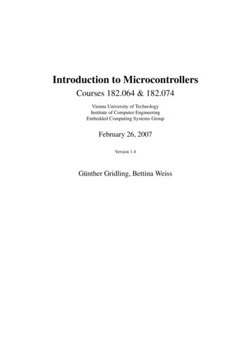
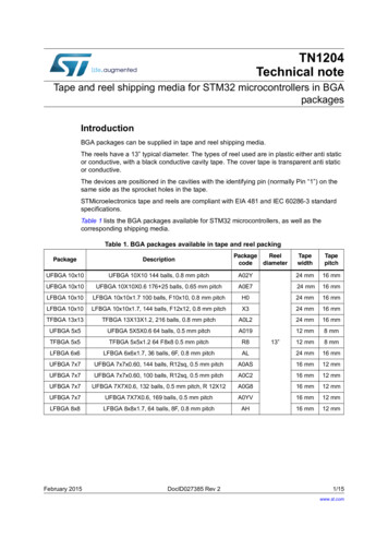
Implementing EEPROM emulation3Implementing EEPROM emulation3.1PrincipleEEPROM emulation can be performed in various ways, taking into consideration the Flashmemory characteristics and final product requirements. The approach detailed belowrequires two sets of Flash memory pages allocated to non-volatile data.The first set of pages is initially erased and used to store new data and Flash programmingoperations are done sequentially in increasing order of Flash addresses. Once the first setof pages is full of data, it needs to be garbage-collected.The second set of pages collects only the valid data from the first set of pages and theremaining area can be used to store new data. Once the transfer of valid data to the secondset of pages is completed, the first set of pages can be erased.Each set of pages can be made up of one or several Flash pages. For most STM32 Seriescovered by this document, a header field that occupies the first four 64-bit words (32 bytes)of each page indicates its status, the exception being STM32 U5 Series, where the headeroccupies the first four 128-bit words (64 bytes). Each page has five possible states: ERASED: the page is empty (initial state) RECEIVE: the page used during data transfer to receive data from other full pages. ACTIVE: the page is used to store new data VALID: the page is full. This state does not change until all valid data is completelytransferred to the receiving page. ERASING: valid data in this page has been transferred. The page is ready to beerased.Figure 1 shows the page status evolution in the case where each set of pages is made oftwo pages.AN4894 Rev 59/4039
Implementing EEPROM emulationFigure 1. Page status evolutionFirst set of Flash pagesSecond set of Flash pagesPage 0Page 1Page2Page 3ACTIVEERASEDERASEDERASEDWrite number of variableelements per page 1 elementVALIDACTIVEERASEDERASEDWrite 2 * number of variableelements per page 1 RASEDERASEDERASEDVALIDACTIVEInitPage Transfer Completed withless than 1 page of valid dataORPage Transfer Completed withmore than 1 page of valid dataPage Erase Completed withless than one page of valid dataORPage Erase Completed withmore than one page of valid dataMSv45025V210/40AN4894 Rev 5
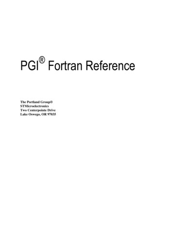
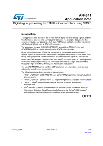
Implementing EEPROM emulation3.2Page status valid transitionsInformation provided in this paragraph is only useful for users intending to modify theEEPROM emulation driver. It is not useful for a simple utilization of the driver.Figure 2. Page status valid transitionsFORMATEEPROMTransfer DATAERASEDWrite DATADATA Transfer to this page completed(page not full)RECEIVEACTIVEWrite DATA (Page Full)DATA transfer from this page completedDATA transfer to this page completed(page full)VALIDDATA transfer from this page completedErase command issued by applicationERASINGMSv45026V1AN4894 Rev 511/4039
Implementing EEPROM emulation3.3Page and variable formatDepending on the STM32 Series, Flash memory page sizes and composition can vary.Moreover, for some STM32 Series, the EEPROM emulation driver supports either singlebank mode, dual bank mode, or both. The right mode must be selected in the EEPROMemulation driver, according to the mode supported. See Table 4 for this information.Table 4. Flash memory propertiesSTM32 Series/Value LinesFlash memory page sizesSingle bank modesupportDual bank modesupportNo(1)YesSTM32L4 Series4 Kbytes (512 words of 64 bits forDBANK 1)STM32L41x/42x/43x44x/45x/46x2 Kbytes (256 words of 64 bits)YesNoSTM32L47x/48x/49x/4Ax2 Kbytes (256 words of 64 bits)YesYesSTM32L552 STM32L5622 Kbytes (256 words of 64 bits) (forDBANK 1)No (1)YesSTM32G0x0STM32G0x12 Kbytes (256 words of 64 bits)YesNoSTM32G4 Series2 Kbytes (256 words of 64 bits) (forDBANK 2WB30CE4 Kbytes (512 words of 64 bits)YesNoSTM32WL Series2 Kbytes (8 rows of 256 bytes)YesNoSTM32WB15CC,STM32WB10CC2 Kbytes (256 words of 64 bits)YesNoSTM32U5 Series8 Kbytes (512 words of 128 bits)YesYes1. When in single bank mode, these devices operate 128 bits wide read accesses. However, the EEPROM emulation solutionis designed for 64 bits wide read accesses.The minimal write width in Flash memory is 64-bits (128-bits for STM32U5 Series) due to itsECC (Error Correcting Code) that cannot be switched off; only zeroes (0x0000 0000 00000000, or 0X0000 0000 0000 0000 0000 0000 0000 0000 for STM32U5 Series) can bewritten to an already programmed non-null Flash line. As the first four words are used by theheader, a Flash page can store up to 252 variable elements when the page size is 2 Kbytes,and up to 508 variable elements when the page size is 4 Kbytes.12/40AN4894 Rev 5
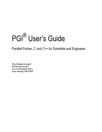
Implementing EEPROM emulationThe possible states of a Flash page are coded by writing 0xAAAA AAAA AAAA AAAA (or0xAAAA AAAA AAAA AAAA AAAA AAAA AAAA AAAA for STM32U5 Series) into the pageheader. It is possible to determine the page state using the following procedure: The page is in ERASING state if its fourth line is not erased The page is in VALID state if the third line is not erased and the fourth line is erased The page is in ACTIVE state if the second line is not erased and the third and fourthlines are erased The page is in RECEIVE state if the first line is not erased and the second, third andfourth lines are erased The page is in ERASED state if the first four lines are erased.This algorithm allows the coding of all states and transitions described in Section 3.2: Pagestatus valid transitions.Each variable element is defined by a virtual address and a data value to be stored in Flashmemory for subsequent retrieval or update. In the implemented software, the virtual addressis 16 bits long and the data value is either 8 bits, 16 bits or 32 bits long. The driver requiresthe virtual address values to be between 0x0001 (0x0000 corresponds to an EEPROMelement invalidated by the driver), and the maximum number of EEPROM variablesrequired. Also, since virtual addresses are 16-bits wide, the maximum number of EEPROMvariables cannot exceed 0xFFFE (0xFFFF corresponds to an erased Flash line). Moreover,the number of variables is limited by the size of the product Flash memory (see Section 4.5:Computing the required size of Flash for EEPROM emulation).Each element also contains a 16-bit CRC that is used to check the element integrity. Whendata is modified, the modified data associated with the same virtual address is stored in anew Flash memory location. Data retrieval returns the up-to-date data value.AN4894 Rev 513/4039
Implementing EEPROM emulationFigure 3. Flash page and EEPROM variable format (except STM32U5 Series)Flash PagePage Header(4 * 8 or ERASED pageVariable Element16-bitVirtualAddress16-bitCRC8, 16 or 32-bitData valuePage Data(Number of variableelements per page* 8 bytes)MSv45027V2Figure 4. STM32U5 Series Flash page and EEPROM variable formatFlash PagePage Header(4 * 16 bytes)RECEIVEACTIVEVALIDERASING0xFFFF FFFF FFFF FFFF FFFF FFFF FFFF FFFFfor ERASED pageVariable Element16-bitVirtualAddress16-bitCRC96-bitData valuePage Data(Number of variableelements per page* 16 bytes)MSv47646V1.14/40AN4894 Rev 5
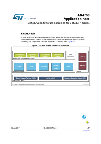
Implementing EEPROM emulation3.4Simple use caseThe following example shows the software management for three EEPROM variables withthe virtual addresses shown in Table 5.:Table 5. Emulated EEPROM virtual addressesVariableVirtual addressData bitFor this example, only two Flash pages are necessary: Page 0 and Page 1. In Figure 5:Data update flow RCRC represents the 16-bit CRC value for this variable element (refer toSection 4.6: EEPROM emulation robustness for more details about CRC).Figure 5: Data update flow shows only the write commands which are done sequentially inincreasing order of Flash addresses.AN4894 Rev 515/4039
Figure 5. Data update flowWrite Var3 0x1245Write Var3 0x1232Format EEPROMPage 0Page 1Page 0Page 1Page 0Page er of variable elements per page - 4) Var3 Writes Write Var2 0x01234567Write Var3 0x1245Data transfer Intermediate stepAN4894 Rev 5Write Var1 0xADADADADPage 0Page 1Page 0Page 1Page 0Page FFFFFFFFFFFFFFFFFFFFFFFFFFFFFFFFFFFData transfer final stepPage RCADADADAD0020RCRC67452301FFFFFFFFFFFFFFFFFFFFPage FFFFFFFFFFFFFPage 0Page 116/40Legend: User commandMSv45028V2Implementing EEPROM emulationClean Up (Erase Page 0)
Implementing EEPROM emulation3.5Reading dataRead commands perform Flash reads from the highest to the lowest address in the ACTIVEor VALID page, and return only valid data. Data is considered valid if it is the latest to bewritten at a given virtual address, and the integrity check using CRC passes. Note also thatonly valid data is copied during the data transfer mechanism.AN4894 Rev 517/4039
Advanced features4Advanced featuresThe EEPROM emulation firmware is designed to fulfill most of the requirements for anembedded application in terms of non-volatile storage. This section covers theserequirements in detail. Other embedded application requirements may be needed inparticular cases and are addressed in section Section 6: Embedded application aspects.4.1Data granularity managementEmulated EEPROM can be used in embedded applications where non-volatile storage ofdata updated with a byte, half-word, or word granularity is required. Data size generallydepends on application requirements such as sensor or communication-interface data size.The EEPROM emulation firmware is designed to support byte, 16-bit half-word and 32-bitword granularity (96-bit word granularity for STM32 U5 Series). However, in order tooptimize the Flash memory usage, the user application could gather all smaller sized dataelements into 32-bit data elements before storing the content in emulated EEPROM. Thiswould ensure an optimal use of the 64-bit Flash line by simultaneously writing the 16-bitvirtual address, the 16-bit CRC and the 32-bit data value.For STM32U5 Series, the user should gather all smaller sized data elements into 96-bitdata- elements before storing the content in emulated EEPROM. This ensures optimal useof the 128-bit Flash line by simultaneously writing the 16-bit virtual address, the 16-bit CRCand the 96-bit data value.Note:The minimal write width in Flash memory is 64 bits (128 bits for STM32U5 Series) due to itsECC (error correcting code), which cannot be switched off.4.2Wear leveling algorithm and Flash page allocationA wear leveling algorithm allows monitoring and even distribution of Flash Write and Eraseoperations between Flash pages. When no wear-leveling algorithm is used, the pages arenot used at the same rate. For instance, pages with long-lived data do not endure as manyWrite and Erase cycles as pages that contain frequently updated data. The wear-levelingalgorithm ensures that equal use is made of all the available write cycles for each Flashpage.By design, the EEPROM emulation algorithm distributes evenly the Flash write and Eraseoperations between Flash pages. Flash writes are performed sequentially in increasingaddress order whatever user variable is written. When one set of pages is full, the validelements are copied to the other set of pages, and the first set of pages is fully erased.18/40AN4894 Rev 5
Advanced features4.3Guard pagesIn order to even further reduce wear on Flash pages, the user can decide to add an evennumber of Flash guard pages (1 guard page per set of pages by default). No guard page isnecessary if the number of emulated variables leaves significant room in the ACTIVE page.Increasing this number (4,6,.) increases the Flash endurance beyond the guaranteedvalue. This feature is closely linked to the emulated EEPROM cycling capability - refer toparagraph Section 4.4: Cycling capability: EEPROM endurance improvement.Taking an example based on the STM32L4, an emulation of 1000 EEPROM variables couldbe stored in two sets of 4 Flash pages (each page being able to store 252 elements). Whenall elements are written once (or after a page transfer), only 8 more elements can be writtenbefore a new page transfer is triggered. In this case, the addition of 2 guard pages isrecommended (one per set of pages) so that 260 writes can be performed before a newpage transfer is triggered.4.4Cycling capability: EEPROM endurance improvementWhen EEPROM technology is used, each byte can be individually programmed a finitenumber of times (typically in the range of 1 million). When Flash technology is used, it is notpossible to write to a non-erased address, and the minimum erase size is the Flash pagesize. Consequently, we need to define a program/erase cycle which consists of severalFlash line write accesses followed by one Flash page erase operation.Each STM32 device on-chip Flash memory page can be programmed and erased reliably alimited number of times. For write-intensive applications that need to update each variablemore than this number, the wear leveling algorithm allows the endurance of the emulatedEEPROM to be increased.Table 6 shows the limit number of reliable programming and erasing operations for devicescovered by this application note:Table 6. Flash memory enduranceSTM32 SeriesFlash memory enduranceSTM32L4 Series10 kcyclesSTM32L4 Series10 kcyclesSTM32L5 Series10 kcyclesSTM32G0 Series10 kcycles (1 kcycles for STM32G030x6/x8 andSTM32G070CB/KB/RB)STM32G4 Series10 kcyclesSTM32WB Series10 kcyclesSTM32WL Series10 kcyclesSTM32U5 Series10 kcycles endurance on all Flash memory.100 kcycles on up to 256 Kbytes per bankKnowing the requested size of emulated EEPROM and the targeted endurance, it is possibleto compute the Flash memory size to be used for that purpose. The Flash memory size isalso a function of the data width of stored variables.AN4894 Rev 519/4039
Advanced featuresTable 7. Flash usage for a 4000-byte emulated EEPROM (STM32L4/L4 )Number ofpagesneeded for10 kcyclesenduranceFlash size for10 kcyclesenduranceNumber of pagesneeded for100 kcyclesenduranceFlash size for100 kcyclesendurance8-bit3468 Kbytes322644(1) Kbytes16-bit1836 Kbytes162324 Kbytes32-bit1020 Kbytes82164 Kbytes8-bit1872 Kbytes162648 Kbytes16-bit1040 Kbytes82328 Kbytes32-bit624 Kbytes42168 KbytesData widthSTM32L4STM32L4 1. Not applicable for STM32L4: a maximum of 512 Kbytes can be allocated to EEPROM emulation. Pleaserefer to the STM32 product datasheet for the size of each bank.Note:20/40To ge
EEPROM emulation techniques and software for STM32 microcontrollers Introduction . memory may be used instead of external EEPROM to store not only code, but also data. . EEPROM endurance improvement