Transcription
DATA SHEETHeadend Optics Platform (CH3000)HT3540H SeriesDouble-Density Full SpectrumDWDM Transmitter SystemFEATURES Available in 40 wavelengths on ITU 100 GHz grid Hot plug‐in/out, individually replaceabletransmitter modules Optimized for full spectrum loading Analog loading up to 552 MHz plus QAM loading Manual or Automatic Gain Control (AGC) modes Low power consumption High rack density: 24 transmitters per 3RUThe CommScope HT3540H Series Double‐Density Full Spectrum DenseWave Division Multiplexing (DWDM) Transmitter System provides highperformance and a high rack density forward path transmission solutionfor Cable TV service providers.The high‐density packaging design allows up to four (4) HT3540H serieshigh performance transmitters plus a CC3008 Communications ControlModule to be stacked vertically and contained by the CA3008 modulecarrier, requiring only two chassis slots of a 3RU chassis. The compactsolution supports up to 24 transmitters in a CH3000 chassis, includingredundant power supplies.chassis, with redundant power supplies andoptical multiplexing Front panel ‐20 dB input test point Front panel laser On/Off switch Local and remote status monitoring features1HT3540H 2022 CommScope, Inc. All rights reserved.
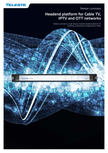
When installed in the chassis, the transmitters interface to a “zero‐slot” back plate, providing support for up to four HT3540Hseries transmitters. The figure below shows a fully loaded carrier mated to the BD35M4 Double‐Density multiplexing back platethat supports optical combining of four DWDM wavelengths in the forward path.HT3540H Series Quad‐Stack and CC3008 CommunicationsModule joined with a BD35M4 Multiplexing Back PlateThe CC3008 Communications Module installed at the top of a HT3540H series transmitter stack provides the communicationsinterface between the transmitters and the CH3000 mid‐plane bus, allowing complete configuration and management control ofthe stack, both local and remote.2HT3540H 2022 CommScope, Inc. All rights reserved.
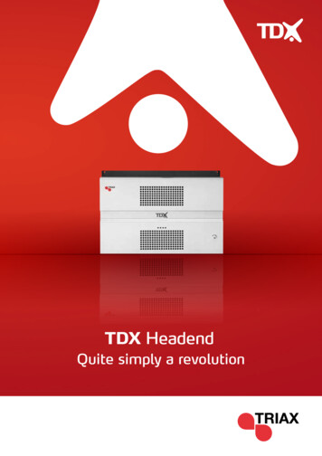
HT3540H Series Double Density Full Spectrum DWDM Transmitters (1.2 GHz Passband)CommScope HT3540H Series Double‐Density Full Spectrum DWDM Transmitters are a key element of the CommScope HFC andFiber Deep architectures in support of the evolution to all QAM transmission. These high‐performance transmitters are designedfor Dense Wave Division Multiplexing (DWDM) applications for point‐to‐point forward path transmission of full spectrumbroadcast and narrowcast services.HT3541H series transmitters are designed for “light” analog channel loading from 0 to 30 analog channels (up to 258 MHz) plusQAM channel loading, or for all QAM loading. They are also designed for QAM‐only loading for digital services as part of a BC/NCoverlay system.HT3542H series transmitters are designed for “full” analog channel loading from 0 to 79 analog channels (up to 552 MHz) plusQAM channel loading.HT3543H series transmitters are designed for all QAM loading.These transmitters incorporate advanced dispersion compensation circuitry to enable transmission of high‐quality signals overmaximum distances.The above figure shows a front view of the CA3008 carrier components: a single HT354xH Double‐Density Transmitter (left); asingle CC3008 Communications Module (right), and a fully loaded “stack” (center) providing four (4) DWDM transmitters,requiring only 2 vertical slots of a CH3000 Chassis. A fully loaded CH3000 chassis supports 24 Double‐Density DWDM transmittersand redundant power supplies.Features DWDM transmitter: 40 wavelengths on the ITU grid Hot plug‐in/out, individually insertable Manual or Automatic Gain Control (AGC) modes Low power consumption RF input amplification up to 6 dB Industry’s highest DWDM rack density: 24 transmittersper 3RU chassis, with redundant power supplies Optimized for full spectrum loading HT3541H: Analog loading up to 258 MHz plus QAMloading, or all QAM loading. HT3542H: Analog loading up to 552 MHz, plus QAMloading Front access ‐20 dB input test point Front panel laser On/Off interlock switch Local and remote status monitoring HT3543H: All QAM loading3HT3540H 2022 CommScope, Inc. All rights reserved.
HT3540H SERIES Dimensions11.5” D x 0.8” H x 2.0” W (29.2 x 2.0 x 5.1 cm)*Weight0.75 lbs. (0.34 kg)* Four (4) transmitter units designed to be vertically stacked, plus a CC3008 Communications Module, and installedinside a CA3008 Module Carrier. The combination occupies two slots in a 3RU CH3000 Chassis.EnvironmentalOperating‐20 to 65 C (‐4 to 149 F)Storage‐40 to 85 C (‐40 to 185 F)Humidity5% to 95% non‐condensingRF and Optical InterfaceRF InputF‐type male located on BD31A4 or BD35M4 Back PlatesInput RF Test PointG‐type male (located at front panel, ‐20 dB)Optical ConnectorSC/APC located on BD31A4 or BD35M4 Back PlatesPower RequirementsInput Voltage12 VDCPower Consumption10 W (per transmitter) including controller and back plate cooling fanGeneralHot plug‐in/outManual gain alignmentChannel LoadingHT3541H: 0–30 Analog channels (up to 258 MHz), plus QAM channelsHT3542H: 0–79 Analog channels (up to 552 MHz), plus QAM channelsHT3543H: All QAM channelsOpticalOptical Output Power10 0.25 dBmWavelengthSee DWDM ITU Channel Plans descriptionFiber LengthHT3541H and HT3543H: 60 km max. (Dispersion Compensation adjustable in 5 km steps)HT3542H: 40 km max. (Dispersion Compensation adjustable in 1 km steps)Compatible with external dispersion compensation for some applicationsElectricalPassband45 to 1218 MHzFrequency Response (Flatness including Slope) 1.0 dB (BC input @ 25 C) 0.5 dB (NC input relative to BC input)Nominal RF Input Levels (Input Attenuator 0 dB)HT3541H: 16.2 dBmV/ch for 30 analog channels into BC input 10.2 dBmV/ch for 256‐QAM channels into BC input, or 16.2 dBmv/ch into NC inputHT3542H: 15 dBmV/ch for 79 analog channels into BC input 9 dBmV/ch for 256‐QAM channels into BC input, or 15 dBmv/ch into NC inputHT3543H: 10.7 dBmV/ch for 154 256‐QAM channels into BC input, or 16.7 dBmV/ch into NC inputRF Input Impedance75 Ω, nomRF Input Return Loss18 dB, minRF Input Attenuator/Amplify Range (Manual Mode)‐6.0 to 5.0 dB Normal mode. High‐gain mode ( 5.5, 6.0 dB) supports BC RF input port, NC RF input is terminated.RF Input Attenuator Step Size0.5 dBAGC ModeMaintains RF level to within 3 dB of the learned RF valueLevel Stability (Typical) 0.5 dB (‐1 worst case relative to 25 C)256‐QAM BER 10–5 (pre‐FEC, ITU‐C)MER 37 dB to 50 C; 36 dB to 65 CLink PerformanceLoadingHT3541HHT3542HHT3543H30A 124 QAM79A 75 QAM154 QAMLength (km)406030404060CNR* (dB):52505150See MERSee MERCSO (dB):61586058‐‐CTB (dB):65656565‐‐* max 1 dB degradation at temperature extremesAn HT3541H transmitter can also be used as a narrowcast transmitter. For example, in BC/NC overlay systems, itwould have the performance of an AT3535G‐xx‐1‐AS transmitter. For more information about BC/NC overlay systemperformance and evolution from low NC 256‐QAM channel loading to full spectrum 256‐QAM channel loading, or forinformation about full spectrum multiwavelength applications with up to 40 DWDM wavelengths, please contact yourCommScope representative.DWDM ITU Channel PlansCommScope supports DWDM network architectures with a variety of products on the standard DWDM ITU Grid (ITU‐T G.694.1). For a more complete description, please refer to the CommScope DWDM ITU Grid Channel Plan datasheet.4HT3540H 2022 CommScope, Inc. All rights reserved.
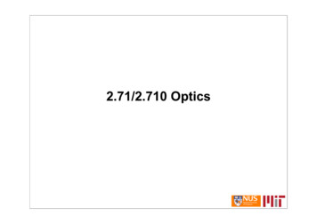
BD35M4‐AC Double‐Density Back PlatesThe CommScope BD35M4‐AC Family of back plates is a 100 GHz grid spacing Double‐Density Mux BackPlate that multiplexes the output of four HT3540H Double‐Density Full Spectrum Transmitters.This back plate provides connections for a group of four HT3540H Series Transmitters installed in the sameCA3008 Module Carrier, along with the CC3008 Communications Control Module.These 4‐channel mux back plates (for which outputs can be cascaded from one back plate to another) maybe ordered for various channel groups.BD35M4‐ACX‐H02F‐Y‐AS Back PlateBD35M4‐AC BACK PLATE Dimensions7.2” D x 5.2” H x 2.0” W* (18.2 x 13.2 x 5.1 cm)Weight2.0 lb. (0.91 kg)EnvironmentalOperating‐20 to 65 C (‐4 to 149 F)Storage‐40 to 85 C (‐40 to 185 F)Humidity5% to 95% non‐condensingPower RequirementsInput Voltage12 VDCPower Consumption5 W max (2.5 W Typ), including the replaceable cooling fanOptical InterfaceOptical ConnectorsSC/APC (2) DWDM INP (input from previous mux back plate) DWDM OUT (output to network or next mux back plate)RF Interface8 F‐Type Connectors 4 BC and 4 NC (1 BC/NC pair per transmitter)OpticalChannel Spacing100 GHzChannel PlanSee ITU Channel Plans descriptionInsertion Losses, Including ConnectorsTypMax DWDM Input to DWDM Output1.0 dB1.2 dB Ch. yy Input to DWDM Output1.4 dB1.6 dB Module Uniformity0.7 dB1.0 dB Paired Uniformity0.4 dB0.6 dBReturn Loss, min45 dBDirectivity, min55 dBUniformity, Including ConnectorsPassband @ 0.2 dB5 Ch. yy Input to DWDM Output 0.125 nm DWDM Input to DWDM OutputPasses 1423.5 through 1617.5 with a notch at the channel add/drop band. WDL for the passband is within 0.15 dBRipple Within Passband0.5 dB maxPolarization Dependent Loss, max0.1 dB (typically 0.05 dB)Power Handling, max (Any Input Port)21.8 dBmHT3540H 2022 CommScope, Inc. All rights reserved.
BD31A4‐100 Double‐Density Back PlatesThe BD31A4 is a double‐density back plate that provides a choice of 4 separate BC and 4 separate NC RF inputs, or 1 common BCand 4 separate NC RF inputs, for four HT3541H Transmitters.The BD31A4‐100 provides RF input and optical connections to or from the HT3541H transmitters.BD31A4‐100‐H12F‐0‐AS is a double density back plate that provides 4 separate BC inputs and 4 separate NC RF inputs for fourHT3541H Transmitters. Also supports four separate optical output SC/APC connectors.BD31A4‐100‐H10F‐0‐AS is a double density back plate that provides 1 common BC input and 4 separate NC RF inputs for fourHT3541H Transmitters. Also supports four separate optical output SC/APC connectors.BD31A4‐100‐H12F‐0‐AS Back PlateCA3008 Module CarrierBD31A4‐100 BACK PLATE Dimensions7.2” D x 5.2” H x 2.0” W* (18.2 x 13.2 x 5.1 cm)Weight2.0 lb. (0.91 kg)EnvironmentalOperating‐20 to 65 C (‐4 to 149 F)Storage‐40 to 85 C (‐40 to 185 F)Humidity5% to 95% non‐condensingPower RequirementsInput Voltage12 VDCPower Consumption5 W max (2.5 W Typ), including the replaceable cooling fanOpticalThrough 4 SC/APC connectors, the BD31A4‐100 provides optical pass‐through from the HT354xH transmitter.Optical Insertion Loss0.2 dB Typ; 0.4 dB MaxRefer to the HT354xH product specifications for more information.RF InterfaceThe BD31A4‐100 provides RF to the HT354xH transmitter through F‐type RF connectors. 4 BC and 4 NC (BD31A4‐100‐H12F‐0‐AS) 1 BC and 4 NC (BD31A4‐100‐H10F‐0‐AS)6HT3540H 2022 CommScope, Inc. All rights reserved.
ORDERING INFORMATIONHT354xH TransmitterDouble Density, Full Spectrum DWDM Transmitter(1.2 GHz)H T354* H – D –***0–2– A S1 Type 1, up to 30A QAM Loading2 Type 2, up to 79A QAM Loading3 Type 3, for all QAM LoadingFor HT3541H and HT3542H A ** ITU Channel #For HT3543H E ** ITU Channel #** ITU Channel Number (20 through 62;See CommScope DWDM ITU Grid Channel PlanData Sheet)Connector Type: SC/APCBack PlatesDouble Density Back plate for 4 HT3xxx FullSpectrum Transmitters with SC/APC ConnectorB D 3 1 A 4 – 1 0 0 – H 1 *F– 0 – A SB D 3 5 M 4 – * * * – H 0 2F– * – A S0 1 common BC input and 4 NC RF Inputs2 4 BC inputs and 4 NC RF InputsConnector Type: SC/APCDouble Density Muxing Back plate for 4 HT354xFull Spectrum Transmitters with SC/APCConnectorHT3541H and HT3542H16 Wavelength PlanHT3541H 40 Wavelength PlanCodeWavelength GroupCodeWavelength GroupHT3543H16 Wavelength PlanCodeWavelength GroupA0JITU CH 20 ‐ 23A0PITU CH 40 ‐ 43CodeWavelength GroupAC1ITU CH 20, 21, 24, 29A0KITU CH 24 ‐ 27A0RITU CH 44 ‐ 47EEAITU CH 21, 22, 24, 26AC2ITU CH 35, 42, 52, 54ITU CH 48 ‐ 51EEBITU CH 28, 33, 36, 39AC3ITU CH 23, 33, 44, 47A0MITU CH 32 ‐ 35A0TITU CH 52 ‐ 55EECITU CH 44, 48, 52, 54AC4ITU CH 51, 57, 58, 59A0NITU CH 36 ‐ 39A0UITU CH 56 ‐ 59EEDITU CH 57, 60, 61, 62A0LITU CH 28 ‐ 31A0SConnector Type: SC/APC1 For up to 30A QAM RF Loading2 For up to 79A QAM RF Loading3 For all QAM RF loading7HT3540H 2022 CommScope, Inc. All rights reserved.
ORDERING INFORMATIONSystem AccessoriesCommunications Control ModuleC C 3 0 0 8Module CarrierC A 3 0 0 8Filler Module for Double‐Density SlotsH T 3FIL DRELATED PRODUCTSCH3000 ChassisOptical Patch CordsOptical TransmittersOptical PassivesDigital ReturnInstallation ServicesContact Customer Care for product information and sales: United States: 866‐36‐ARRIS International: 1‐678‐473‐5656Note: Specifications are subject to change without notice.Copyright Statement: 2022 CommScope, Inc. All rights reserved. ARRIS and the ARRIS logo are trademarks of CommScope, Inc. and/or its affiliates. All other trademarks are the property of their respective owners. No part ofthis content may be reproduced in any form or by any means or used to make any derivative work (such as translation, transformation, or adaptation) without written permission from CommScope, Inc and/or its affiliates(“CommScope”). CommScope reserves the right to revise or change this content from time to time without obligation on the part of CommScope to provide notification of such revision or change.87‐10845‐RevT HT3540 �2022 EA‐34784
high performance and a high rack density forward path transmission solution for Cable TV service providers. SYSTEM OVERVIEW DWDM transmitter: up to 40 wavelengths on ITU grid Hot plug‐in/out, individually replaceable transmitter . Operating -20 to 65 C (-4 to 149 F) ‐‐‐‐ Headend Optics .