Transcription
ROBOTICS FOR BEGINNERBased On Digital & Analog ElectronicsBy:Er.Tejinder DevgonVol.1Embedded System *Robotics* PCB Designing & Simulation * Matlab Simulation * Aeromodelling6 Month / 6 Weeks Industrial TrainingMajor and Minor Projects / Thesiswww.strobotix.comSTrobotix, Sec-41B, Chandigarh Ph- 01722-636402, 9988218770, 9988091747
PrefaceThis is a professional book. In this I concentrate on sharing my experienceon robotics and this book is especially designed for beginners in robotics.This book is dedicated to all Indian robotics newbie’s. In this book I willtalk about the electronics basics you should know in robotics. The mainreason for writing this book is that newbie’s face a lot of trouble withcircuits and most of them use readymade circuits they get from Internetand they waste time over it because they don't know how to troubleshootthe circuit. I faced same problems many times. So in this book I am tellingthe practices which I followed and troubleshooting techniques which Iused for circuits. A beginner could make any kind of minor or majorproject of electronics and robotics with the knowledge, resources andtroubleshooting techniques of almost all the types of electronicscomponents that are studied at the time of engineering.This book consists of ideas of my colleagues of my company STrobotix, &IET Bhaddal Alumni. I thank my Father Er.Inderjit Kumar (Mechanical),my Brother Er. Pardeep Kumar (Software Engineer) & my friendsEr. Shakshi Rana (R & D Head, STrobotix), Er.Ankit Singh Rana (JRFDRDO) & all people related to STrobotix in anyway. This is my first steptoward spreading robotics Knowledge to the robotics beginners &Engineers that resulted in this book. So I feel this book can guide youthrough troubleshooting electronic circuits in robotics and understandingthe basic electronics.If you find any problem Visit na99@yahoo.intejinder robotix.comEr.Tejinder arhSTROBOTIXContact: Er.Tejinder Devgon - 09988218770Er.Shakshi Rana – 09888091747Embedded System *Robotics* PCB Designing & Simulation * Matlab Simulation * Aeromodelling6 Month / 6 Weeks Industrial TrainingMajor and Minor Projects / Thesiswww.strobotix.comSTrobotix, Sec-41B, Chandigarh Ph- 01722-636402, 9988218770, 9988091747
If you have an apple and I have an apple and we exchange these applesthen you and I will still each have one apple. But if you have an idea andI have an idea and we exchange these ideas, then each of us will havetwo ideas.George Bernard ShawEmbedded System *Robotics* PCB Designing & Simulation * Matlab Simulation * Aeromodelling6 Month / 6 Weeks Industrial TrainingMajor and Minor Projects / Thesiswww.strobotix.comSTrobotix, Sec-41B, Chandigarh Ph- 01722-636402, 9988218770, 9988091747
Steps to learn Robotics1. In robot you need an electronic circuit, mechanicalcomponents such as wheels, motor and other toys stuff. Inthis book every requirement will be explained step by step2. First of all in order to learn to make circuit, you should needto know about every electronic component, theirspecification, company make, their size, rating and allparameter should be at you tips.You have to be able to recognize each and every electroniccomponents and its detail.The company which makes an electronic component, theyalso provide its datasheet and application note.Every component has datasheet or manual.Datasheet are best source to get information aboutelectronics components.3. Now after getting information about each components, nextstep is how to use different components to make an circuit4. First of all use breadboards to make circuit , then aftercompeting circuit on breadboard ,make the same circuit ongeneral purpose PCB5. Further tips to make robots are given step by step infollowing chapters6. This is a complete application book giving applicationcircuits of most of the electronic components that areavailable in the market near your place and tells about yourcommon errors in connections of a circuit.In this book, I have given all the knowledge regarding basicelectronics and digital electronics and their applications inRobotics. My aim was to make the students aware aboutapplications of the basic electronics concepts without anyinvolvement of microcontrollers in this book. This book wouldbe a first step towards robotics for the beginners. I would beincluding microcontrollers and its applications in my secondedition book.Embedded System *Robotics* PCB Designing & Simulation * Matlab Simulation * Aeromodelling6 Month / 6 Weeks Industrial TrainingMajor and Minor Projects / Thesiswww.strobotix.comSTrobotix, Sec-41B, Chandigarh Ph- 01722-636402, 9988218770, 9988091747
PART- I: Electronic Components and Sensors knowledgeBREADBOARDBreadboard is used to make circuits. But mostly after testing yourcircuits on breadboard you will be making PCB. But I never madePCB for any of my circuits. Normally everyone says that if youconnect on breadboard then wires may get loose and circuit willget disturbed due to shock. But no such problem occurred to me,all you have to do is to do a good wiring. Then you can gain timefor making PCB's.Above diagram shows how breadboard connections should bemade. So all you require is to do a good wiring. First I will tellabout which breadboard should you use. The breadboard isdifferent mainly according to the size of their holes. Thebreadboard in Figure.1 has the smallest whole size.This breadboard has medium sized holes. I mostly prefer this one.But I have not seen this breadboard nowadays. The one which isavailable nowadays is given below. Breadboards costs from Rs.80120 (depends on place where you are in India). The main problemwith small holes is that, it will be tough to insert IC's like 7805power transistors so on. Even there is problem with size of wiresalso.Following figures show good wiring practices you should follow so thatyour circuit won't be disturbed by any shocks.Embedded System *Robotics* PCB Designing & Simulation * Matlab Simulation * Aeromodelling6 Month / 6 Weeks Industrial TrainingMajor and Minor Projects / Thesiswww.strobotix.comSTrobotix, Sec-41B, Chandigarh Ph- 01722-636402, 9988218770, 9988091747
In this you can see that the length of the wires used is of exact lengthbetween two points. If you do this type of wirings then no problems occur.But in this you can see that resistor is not properly inserted, for this youshould cut the leads of the resistor so that its body is just touching (ortouching the breadboard).Embedded System *Robotics* PCB Designing & Simulation * Matlab Simulation * Aeromodelling6 Month / 6 Weeks Industrial TrainingMajor and Minor Projects / Thesiswww.strobotix.comSTrobotix, Sec-41B, Chandigarh Ph- 01722-636402, 9988218770, 9988091747
Fig: Good connectionAbove figures shows how to make good connections. In last one you cansee how they made connections so that no problems will occur. Below youcan see what connections you should not have to do.Fig: Poor ConnectionAfter testing your circuit you have to make it on PCB boards.Mostly PCB I saw in industries is of three types of material1. Paper phenolic ( Low cost , mostly used )2. Paper Expoxy3. Epoxy glass ( High Cost , high quality )Embedded System *Robotics* PCB Designing & Simulation * Matlab Simulation * Aeromodelling6 Month / 6 Weeks Industrial TrainingMajor and Minor Projects / Thesiswww.strobotix.comSTrobotix, Sec-41B, Chandigarh Ph- 01722-636402, 9988218770, 9988091747
PROBLEMS OCCURING WITH BREADBOARD1. As I said above some breadboards will be difficult to insert IC‘slike 7805, LM317 etc. Due to the small sized holes.2. I bought a new breadboard for Rs.80 in which some parts of thebreadboard are not working. So you should be careful about it.3. Some part of the breadboard may suddenly create problem. Thisproblem will mostly eat your time. I have connected full circuitfor my project and it was working properly two months ago. Thecircuit consist of a 7805 which convert adapter DC to 5V. Nowwhen I switch ON power supply, the circuit is not working. Onexamination I found that the output voltage of 7805 is 1.1V eventhough input voltage to 7805 is 7.5. I was surprised to see thisbecause I had done same circuit a month ago and no changesmade in circuit. Then I used another breadboard especially for7805 to make connections, surprisingly it is working fine giving4.8-5V.Then I connected the output from that breadboard to myoriginal board where circuit was connected. It is working fine.Then I again tried in same position it is not working givingoutput of adapter 3-4V and output of 7805 1.1V. I doubted ifthe voltage regulator input is low to regulate, so I increased theadapter to 9V from 7.5(my adapter has varying voltage startingfrom 1.5V, 3V.). Then the light of the adapter went off. Then Iagain increased voltage to 12V. Then also light is off. Now Idecided for a new position of breadboard, where it workedproperly. Then I increased voltage up to 13.5V. For all theseinput voltages to 7805 the input of 7805 still remained 3.5-3.7Vand output .7-.8V. Finally I got a position of the breadboardwhere it worked fine. The problem was of the position in thebreadboard which I used.4. One similar problem occurred when I connected LM324 with itsinput a variable resistor. I rotated the knob of the potentiometer(it has one end on Vcc 10v, other end on ground and middleend is connected to the LM324), the voltage output of thepotentiometer is suddenly increasing from .5 to 8.8V suddenlywith a small rotation of the knob. I tried to rotate shaft byconnecting the middle end to another portion of the breadboard,there it worked fine. I used the same portion of the breadboardwhere I connected first and tried the same after removingLM324, and then also it is working fine. Then I again connectedLM324 in same position, still the old problem came. Then Ichanged the full circuit to another position of the breadboard, itworked fine.Embedded System *Robotics* PCB Designing & Simulation * Matlab Simulation * Aeromodelling6 Month / 6 Weeks Industrial TrainingMajor and Minor Projects / Thesiswww.strobotix.comSTrobotix, Sec-41B, Chandigarh Ph- 01722-636402, 9988218770, 9988091747
MULTIMETERMultimeter is used to measure different parameters like voltage,current, resistance etc. In robotics you should use a multimeterwhich is capable of measuring voltage, résistance, continuity test,transistor (hfe). Cost of a multimeter depends on the number ofquantities it can measure; even some multimeter's can testwhether a diode is of Ge or Si. But we don't want that much costlymultimeter. A cheap one which I use is about Rs.300 which has allthe necessary facilities which we commonly uses (voltage,resistance, and continuity). See my multimeterSuppose if you want to measure output voltage of an adapter, seewhat is the maximum voltage of adapter (mostly around 15V).Then put the needle to 20V (a voltage greater than 15V). A displayof '1' on multimeter means that it is not able measure the quantityin that position of the needle.Suppose if you want to measure a resistance and you put theneedle to the 20Kohm, then if multimeter shows '1' then put theneedle to 200Kohm, because the resistance is greater than20Kohm. Same with all the measurements like voltage, currentetc. When you are buying a multimeter you must see thatmultimeter should be able to do continuity test (it is the easurement. These three are the important quantities youmeasure in robotics.If you want to study more about multimeter see the following /www.doctronics.co.uk/meter.htmlEmbedded System *Robotics* PCB Designing & Simulation * Matlab Simulation * Aeromodelling6 Month / 6 Weeks Industrial TrainingMajor and Minor Projects / Thesiswww.strobotix.comSTrobotix, Sec-41B, Chandigarh Ph- 01722-636402, 9988218770, 9988091747
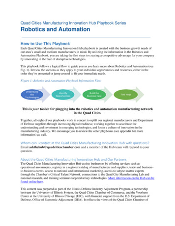
RESISTORResistors offers a resistance to the flow of current And act asvoltage droppers or voltage dividers. They are "Passive Devices",that is they contain no source of power or amplification but onlyattenuates or reduce the voltage signal passing through them.We mostly use resistance in this rangeeven though more power rating highvalue resistors are available (power up to600 watt and resistor value up to 1giga ohm). So when you select a resistorits value and power rating should be thedeciding parameter. Therefore for highcurrent operations we use resistance ofhigher current ratings. The size of theresistor determines its power rating (i.e.as size/thickness increases power/current carrying capacity ofresistance increases)Types of resistorsMainly they are of two typesa. Fixed resistorsb. Variable resistorsEmbedded System *Robotics* PCB Designing & Simulation * Matlab Simulation * Aeromodelling6 Month / 6 Weeks Industrial TrainingMajor and Minor Projects / Thesiswww.strobotix.comSTrobotix, Sec-41B, Chandigarh Ph- 01722-636402, 9988218770, 9988091747
Basic Parameters of Resistance1 .Value (measured in ohms)2. Power rating (in watt)3. Resistance Tolerance (e.g. 1%, 2%, 5%, 10%, 15% etc.)4. Dimensions L*B*H (used in bussed type resistors)5. Maximum operating voltage (in volts)6. Operating temperature (in degree centigrade)7. Temperature coefficient (in ppm/ c)8. Body diameter in mm (used in axial type resistors)9. Lead length and diameter (used in axial type resistor)10. Insulating resistance ( 1000MὨ)11. Lead pitch (in mm)12. Dielectric strength (in volts)These are the main parameters of the resistor which that specify aparticular type resistor.Types of resistors according to there composition1.2.3.4.Carbon resistorMetal film resistorWire woundSemiconductor resistance1. Carbon ResistorsResistors are the most common type ofComposition Resistors as they are a cheapgeneral purpose resistor. Their resistiveelement is manufactured from a mixture offinely ground carbon dust or graphite(similar to pencil lead) and a nonconducting ceramic (clay) powder to bind itall together. The ratio of carbon to ceramicdetermines the overall resistive value of themixture and the higher this ratio is the lower the resistance. Themixture is then moulded into a cylindrical shape and metal wiresor leads are attached to each end to provide the electricalconnection before being coated with an outer insulating materialand colourEmbedded System *Robotics* PCB Designing & Simulation * Matlab Simulation * Aeromodelling6 Month / 6 Weeks Industrial TrainingMajor and Minor Projects / Thesiswww.strobotix.comSTrobotix, Sec-41B, Chandigarh Ph- 01722-636402, 9988218770, 9988091747
Fig: Carbon resistanceCarbon Composite Resistors are low to medium power resistorswith low inductance which makes them ideal for high frequencyapplications but they can also suffer from noise and stability whenhot. Carbon composite resistors are prefixed with a "CR" notation(e.g. CR10kΩ) and are available in E6 ( 20% tolerance (accuracy)),E12 ( 10% tolerance) and E24 ( 5% & 2% tolerance) packageswith power ratings from 0.125 or 1/4 Watt up to 2 Watts.2. Metal Film ResistorsThe generic term "Film Resistor" consist of Metal Film, CarbonFilm and Metal Oxide Film resistor types, which are generally madeby depositing pure metals, such as nickel, or an oxide film, suchas tin-oxide, onto an insulating ceramic rod or substrate. Theresistive value of the resistor is controlled by increasing thedesired thickness of the film and then by laser cutting a spiralhelix groove type pattern into this film. This method ofmanufacture allows for much closer tolerance resistors (1% orless) ascompared to the simpler carbon composition types.Embedded System *Robotics* PCB Designing & Simulation * Matlab Simulation * Aeromodelling6 Month / 6 Weeks Industrial TrainingMajor and Minor Projects / Thesiswww.strobotix.comSTrobotix, Sec-41B, Chandigarh Ph- 01722-636402, 9988218770, 9988091747
3. Wire wound ResistorsWire wound resistor types are prefixed with a "WH" or "W" notation(eg WH10Ω) and are available in the WH Aluminum Claddedpackage ( 1%, 2%, 5% & 10% tolerance) or the W VitreousEnameled package ( 1%, 2% & 5% tolerance) with power ratingsfrom 1W to 300W or more.4. Semiconductor Resistors –High frequency/precision surface mount thin film technology. Itis the only resistor which is active remaining all is passive.Fig: Semiconductor ResistanceEmbedded System *Robotics* PCB Designing & Simulation * Matlab Simulation * Aeromodelling6 Month / 6 Weeks Industrial TrainingMajor and Minor Projects / Thesiswww.strobotix.comSTrobotix, Sec-41B, Chandigarh Ph- 01722-636402, 9988218770, 9988091747
5. VaristorsSmall sizeVaristors voltage: 82VRated peak single pulse transient current: 800AMaximum clamping voltage at 5A: 145VApplications:Transistor, IC, thyristor, or triad semiconductor protectionSurge protection in consumer electronicsSurge protection in industrial electronicsElectrostatic discharge and noise suppressionRelay and electromagnetic value surge absorptionSurge protection in communication, measuring, or controllerelectronicsFig: SIP/DIL ResistanceFig: shunt resistanceFig: Wire wound ResistanceEmbedded System *Robotics* PCB Designing & Simulation * Matlab Simulation * Aeromodelling6 Month / 6 Weeks Industrial TrainingMajor and Minor Projects / Thesiswww.strobotix.comSTrobotix, Sec-41B, Chandigarh Ph- 01722-636402, 9988218770, 9988091747
SIZE INCRESEAS POWER INCREASESAccording to above diagram we can conclude that , size ofresistance define its power ratingWhere higher current rating are required , large size resistance isused.Embedded System *Robotics* PCB Designing & Simulation * Matlab Simulation * Aeromodelling6 Month / 6 Weeks Industrial TrainingMajor and Minor Projects / Thesiswww.strobotix.comSTrobotix, Sec-41B, Chandigarh Ph- 01722-636402, 9988218770, 9988091747
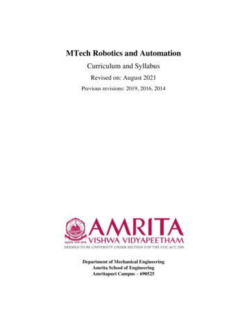
A POTENTIOMETER (colloquially known as a "pot") is a threeterminal resistor with a sliding contact that forms anadjustable divider. If only two terminals are used (one side and thewiper), it acts as a variable resistor or rheostat. Potentiometersare commonly used to control electrical devices such as volumecontrols on audio equipment. Potentiometers operated by amechanism can be used as position transducers, for example, ina joystick.Potentiometers are rarely used to directly control significant power(more than a watt), since the power dissipated in thepotentiometer would be comparable to the power in the controlledload (see infinite switch). Instead they are used to adjust the levelof analog signals (e.g. volume controls on audio equipment), andas control inputs for electronic circuits. For example, alight dimmer uses a potentiometer to control the switching ofa TRIAC and so indirectly control the brightness of lamps.(US)(Europe)Electronic SymbolA typical single-turn potentiometerLinear potentiometers ("faders")PCB mount trimmer potentiometers, or"trimpots", intended for infer quent adjustment.Embedded System *Robotics* PCB Designing & Simulation * Matlab Simulation * Aeromodelling6 Month / 6 Weeks Industrial TrainingMajor and Minor Projects / Thesiswww.strobotix.comSTrobotix, Sec-41B, Chandigarh Ph- 01722-636402, 9988218770, 9988091747
Ten Turn Potentiometer, KnobSquare trimming potentiometer,Carbon PotentiometerPotentiometer precision multiturn metal shaftElectronics SymbolsPotentiometer is mostly used as voltage dividerEmbedded System *Robotics* PCB Designing & Simulation * Matlab Simulation * Aeromodelling6 Month / 6 Weeks Industrial TrainingMajor and Minor Projects / Thesiswww.strobotix.comSTrobotix, Sec-41B, Chandigarh Ph- 01722-636402, 9988218770, 9988091747
Some of the leading Companies ManufacturingVarious Kinds of ResistancesHigh Precision Variable Resistors 10 OhmCeramic body Wirewound resistorsMetal Film ResistorsSIL ResistancesBourns Potentiometer Current Sense ResistorsCarbon ResistorsThick Film ResistorsSurface mount precision resistorEmbedded System *Robotics* PCB Designing & Simulation * Matlab Simulation * Aeromodelling6 Month / 6 Weeks Industrial TrainingMajor and Minor Projects / Thesiswww.strobotix.comSTrobotix, Sec-41B, Chandigarh Ph- 01722-636402, 9988218770, 9988091747
CAPACITORA capacitor is used to store charge. Like resistors there is fixed aswell as variable capacitor also. But we mostly use fixed capacitorin robotics; variable capacitors are mainly used in analogcommunication. There are capacitors with no polarity and polarity.Ceramic and Mica capacitors available are of no-polarity, butelectrolytic capacitors are of polarity. There is a variation in theirsymbols also.Mica CapacitorCeramic CapacitorElectrolytic CapacitorIn the above figure we can see that the different symbols forcapacitors. Mica and ceramic capacitor don't have polarity whileelectrolytic have polarity, so one lead of electrolytic capacitor isbend (-ve lead). We can identify negative lead of electrolyticcapacitor by checking the length of the lead, one with less lengthis -ve. On the body of electrolytic capacitor -ve symbol is shown.Be careful about Electrolytic capacitor because inverting polaritycan make explosion' (not firing) of capacitor (sometimes it canhurt your body).Basic Parameters of Capacitor :1.2.3.4.5.6.7.CapacitanceToleranceOperating TemperatureDimensionsLeakage currentIts terminalsFactors for classification of capacitor are Its capacitance andvoltage.Embedded System *Robotics* PCB Designing & Simulation * Matlab Simulation * Aeromodelling6 Month / 6 Weeks Industrial TrainingMajor and Minor Projects / Thesiswww.strobotix.comSTrobotix, Sec-41B, Chandigarh Ph- 01722-636402, 9988218770, 9988091747
TYPES OF CAPACITORS:1. Electrolytic CapacitorElectrolytic Capacitors are generally used when very largecapacitance values are required. Here instead of using a very thinmetallic film layer for one of the electrodes, a semi-liquidelectrolyte solution in the form of a jelly or paste is used whichserves as the second electrode (usually the cathode). The dielectricis a very thin layer of oxide which is grown electro-chemically inproduction with the thickness of the film being less than tenmicrons. This insulating layer is so thin that it is possible to makecapacitors with a large value of capacitance for a small physicalsize as the distance between the plates, d is very small.Fig: Typical electrolytic capacitorElectrolytic Capacitors are generally used in DC power supplycircuits due to their large capacitances and small size to helpreduce the ripple voltage or for coupling and decouplingapplications. One main disadvantage of electrolytic capacitors istheir relatively low voltage rating and due to the polarization ofelectrolytic capacitors, it follows then that they must not be usedon AC supplies.Electrolytic's generally come in two basic forms; AluminumElectrolytic Capacitors and Tantalum Electrolytic Capacitors.Tantalum capacitor takes lesser space as compared to electrolyticcapacitor but cost moreEmbedded System *Robotics* PCB Designing & Simulation * Matlab Simulation * Aeromodelling6 Month / 6 Weeks Industrial TrainingMajor and Minor Projects / Thesiswww.strobotix.comSTrobotix, Sec-41B, Chandigarh Ph- 01722-636402, 9988218770, 9988091747
2. Ceramic capacitor:Typical values of capacitance for an aluminum electrolyticcapacitor range from 1uF up to 47,000uF and for a tantalumcapacitor range from 47nF to 470uF. Mica CapacitorsThese are available in the values of typically less than 0.1uFcapacitance. They are extremely shock resistant, include a highdV/dt rating, and maintain their capacitance over a very teristics, mica capacitors can be used in high-power, highcurrent RF broadcast transmitters, defense electronics (jet aircraft,missiles, etc.), and also in power conversion circuits for lowcapacitance snubber applications. These capacitors are found inradio/TV transmitters, cable TV amplifiers, avionics, and highvoltage inverter circuits. Specific characteristics that should beconsidered when choosing the appropriate mica capacitor includerated voltage (VDC), Peak RMS Voltage (Vrms), and Case/PackageType.Note: - there is a formula to calculate the value of the ceramic capacitorwhich is shown in the following figure.Multilayer ceramic capacitorRF ceramic capacitorEmbedded System *RoboticsCeramic capacitorDisc ceramic capacitorSuper High Voltage DiscCeramic capacitor* PCB Designing & Simulation * Matlab Simulation * Aeromodelling6 Month / 6 Weeks Industrial TrainingMajor and Minor Projects / Thesiswww.strobotix.comSTrobotix, Sec-41B, Chandigarh Ph- 01722-636402, 9988218770, 9988091747
How to find values of capacitance?Every capacitor has two factors - value of its capacitance andother the maximum voltage rating.For an electrolytic capacitor, this is notImportant Things about Capacitor:Capacitances vary from 22pF to about 15000uF. Values .1uF aremainly mica and ceramic capacitors and C 1uF are electrolyticcapacitors. See the maximum voltage ratings of capacitor whenyou select electrolytic capacitors. Electrolytic capacitor ‗explodes'when you invert polarity of capacitor and applying voltage aboutmaximum rated voltage. When you see circuit, be careful aboutthe symbols of capacitor used to choose which one you require(Electrolytic or ceramic).Embedded System *Robotics* PCB Designing & Simulation * Matlab Simulation * Aeromodelling6 Month / 6 Weeks Industrial TrainingMajor and Minor Projects / Thesiswww.strobotix.comSTrobotix, Sec-41B, Chandigarh Ph- 01722-636402, 9988218770, 9988091747
3. Tantalum capacitor:These are also the like electrolytic capacitor but they are highly reliable. Itssurface is mounted with tantalum. These type have low leakage and greatcapacitance.Images:-Internal structure of Tantalum capacitorTantalum capacitor4. Trimmer: - Trimmer capacitors are the variable capacitor.Ceramic trimmer capacitorTrimmer capacitorTrimmer cap or Variable cap.Embedded System *Robotics* PCB Designing & Simulation * Matlab Simulation * Aeromodelling6 Month / 6 Weeks Industrial TrainingMajor and Minor Projects / Thesiswww.strobotix.comSTrobotix, Sec-41B, Chandigarh Ph- 01722-636402, 9988218770, 9988091747
5. Polypropylene:- Ideal for use in power semiconductor circuits to suppressor attenuate undesired voltages peak.Polypropylene radial capacitor(High Voltage)Polypropylene Film capacitor6. Polyester:- These type of capacitor has high tolerance and these types ofcapacitors are used in blocking, bypassing, filtering, coupling and decoupling,interference suppression in low voltage circuitPolyester film capacitor (radial)7. Polystyrene:- These capacitors has high stability and low losscharacteristics.8. ElectricalAluminum electrolytic motor startcapacitors, housed in a mounded polycarbonate case. Thesetypes of the capacitor are suitable for small and medium sizeelectric motors.Embedded System *capacitor:-Robotics* PCB Designing & Simulation * Matlab Simulation * Aeromodelling6 Month / 6 Weeks Industrial TrainingMajor and Minor Projects / Thesiswww.strobotix.comSTrobotix, Sec-41B, Chandigarh Ph- 01722-636402, 9988218770, 9988091747
Some of the leading CompaniesVarious Kinds of CapacitorsManufacturingTantalum and Polyster CapacitorsElectrolytic CapacitorsSuppression CapacitorsAluminum and film capacitorsCeramic and Tantalum CapacitorsElectrolytic and Polyester CapacitorsEmbedded System *Robotics* PCB Designing & Simulation * Matlab Simulation * Aeromodelling6 Month / 6 Weeks Industrial TrainingMajor and Minor Projects / Thesiswww.strobotix.comSTrobotix, Sec-41B, Chandigarh Ph- 01722-636402, 9988218770, 9988091747
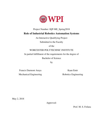
DiodesCurrent flows from anode to cathode when the diode is forwardbiased. In a normal forward biased diode, energy is dissipated asheat in the junction, but in LED's energy dissipated as visiblelight. In robotics we use normal diodes as freewheeling diodes or tomake power supply. LED's are of two types - IR led and normalLED. IR LED emits Infra Red radiations while normal LED emitvisible light. So first talk about a normal diode. Mostly we us1N4001 or 1N4007 as freewheeling diodes for motors or relays,sometimes in H-bridge also.From the above figure try to find out which diodes are forwardbiased and which are reversed biased. You can see that a) isrepresents symbol of a diode b), d) are forward biased and c) isreverse biased(voltage at the P N junction should be greater than Njunction by .7V).Figure shows normal diodes with different power ratings. Idon't know about the transistor type diodes. High powerrating diodes are used for high power motors. The followingfigure shows the normal diode available in the market.Diodes shown above are commonly known as rectifying diodesEmbedded System *Robotics* PCB Designing & Simulation * Matlab Simulation * Aeromodelling6 Month / 6 Weeks Industrial TrainingMajor and Minor Projects / Thesiswww.strobotix.comSTrobotix, Sec-41B, Chandigarh Ph- 01722-636402, 9988218770, 9988091747
Above figure shows how to bend the leads of a diode and a resistorso that a properly inserted into breadboard or PCB. But remembernot to bend too close to body. But there are different diodes LED,IRLED, Photo Diode, and Zener Diode. But in robotics we use LED,IR LED‘s, and Photo Diodes. Diode and Zener diodes are used, butrarely.Can u tell the voltage? Vcc ranges from 0-50 (it can go up to 200valso, for high power diodes). V range from .65 to .8 depending onseries resistance (.7V)Embedded System *Robotics* PCB Designing & Simulation * Matlab Simulation * Aeromodelling6 Month / 6 Weeks Industrial TrainingMajor and Minor Projects / Thesiswww.strobotix.comSTrobotix, Sec-41B, Chandigarh Ph- 01722-636402, 9988218770, 9988091747
Full Bridge Rectifier DiodesFor AC to DCconversion inpower supplyHigh Power Diodes ( 100 amp)Laser DiodesEmbedded System *RoboticsZener diodeDVD laser Diode* PCB Designing & Simul
electronics and digital electronics and their applications in Robotics. My aim was to make the students aware about applications of the basic electronics concepts without any involvement of microcontrollers in this book. This book woul