Transcription
Qualification & Certification ofAdditively Manufactured Partsfor NASA ApplicationsNASA Safety Center, WebinarDecember 11, 2018
Welcome and Webinar ObjectivesWelcome to Qualification & Certification of Additive Manufactured (AM) Parts forNASA Applications.This webinar is intended for our NASA Safety and Mission Assurance (S&MA)community to support their significant role in additive manufactured hardware forNASA applications.Webinar Objectives: Reinforce a basic understanding of AM processes. Become familiar with MSFC-STD-3716 requirements for metal spaceflighthardware. Review key quality assurance products from MSFC-STD-3716. Learn about important AM defect types and how to detect them. Learn about the challenges and best practices for nondestructive evaluation(NDE) of metal AM parts.
Section 1Background to AdditiveManufacturing
Background Additive Manufacturing (AM) isrevolutionizing aerospace design andmanufacturing. AM is the process of building hardwarelayer by layer with fewer parts yet morecomplex designs. This reduces costs andwaste, while enabling unprecedenteddesign freedom and challenging the orderof the traditional aerospace hardwaredevelopment cycle. For existing designs, the cost and time needed to make a part can be reduced, especially for one-of-akind or limited quantity production runs common in NASA’s programs. Repair of existing hardware isalso a possible future application. For new designs, reliance on meticulous analysis to mitigate part failure may be reduced sinceprototype hardware designs can now be iterated (during Design, Development, Test and Evaluation)with reduced cost and impact to schedule.
Background While other AM processes are mentioned in this webinar, powder bed fusion (PBF) isthe current leader among different AM processes for making quality metal aerospacehardware. In PBF, metal powder is fused layer-by-layer using a high-energy electron or laserbeam. After one layer is fused, a new powder layer is spread on the newly solidifiedsurface, and that layer fused. The process continues until the part rests in a bed of unfused powder, giving PBF its name. Multiple factors affect AM part quality: Feedstock consistencyLaser power, hatch width, scan rateThermal conditions during buildBuild chamber atmospherePost-processingWorker trainingEquipment calibration and maintenanceAnd so forth
Background For NASA, Agency standards for theproduction of consistent, high-qualitymetallic spaceflight hardware are underdevelopment. The only currently availablestandard is MSFC-STD-3716. Requirements in MSFC-STD-3716 establisha methodology to control process variablesand manage the risks associated with thisnew technology. A companion specification, MSFC-SPEC-3717, providesdetailed procedures for: Equipment calibration and controlPersonnel trainingQualified Metallurgical Process (QMP) development
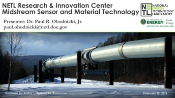
Definition of Additive Manufacturing(ISO/ASTM 52900-15 Terminology for AM)additive manufacturing (AM), n—the process of joining materials to make partsfrom 3D model data, usually layer upon layer, as opposed to subtractivemilling, turning,drilling, EDM etc.manufacturing and formative manufacturing methodologies.forging, bending, casting, injection molding, compaction ofgreen bodies in powder metallurgy or ceramic processing, etc.DISCUSSION—The meaning of “additive”, “subtractive” and “formative”manufacturing methodologies are further discussed in Annex A1.AdditiveSubtractive
Additive Manufacturing Processes Powder Bed Fusion (PBF) via: Selective Laser Sintering (SLS) Selective Laser Melting (SLM) Electron Beam Melting (EBM) SLM and EBM parts are fullymelted during processing. SLS parts are partially melted(sintered) during processing. Note: Direct Metal Laser Sintering(DMLS), which despite its name,involves full melting of the powder,and thus production of a fully densepart, is not a true sintering process.
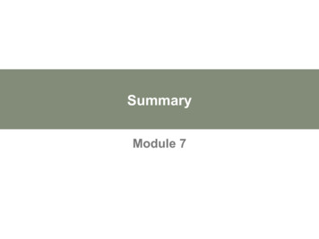
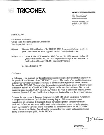
Additive Manufacturing Processes Powder Bed Fusion (PBF) A moving head a) selectively binds the surface of apowder bed e). A moving platform f) progressively lowers the bed. The solidified object d) rests inside the unbound powder. New powder is added to the bed from a powderreservoir c) by means of a powder scraper(recoater blade) b). A thin layer ( 0.001 in.) of metal powderis melted (or sintered) by finely focusedlaser rastering across the build area.abecd The scale of SLM is limited: Common: 250 250 325 mm Large: 800 400 500 mm New target: 1000 mm dimensionfSource: Bits into Atoms 3D Printing and Design, "High Level Processes: Powder Bed Fusion“ (2017). https://www.bintoa.com/powder-bed-fusion/.
Additive Manufacturing Processes Powder Bed Fusion (PBF) Combustion chamber liner fabrication showing the contouring (outside edges)pass (left), in-fill pass (middle), and finish liners -4625
Additive Manufacturing Processes Directed Energy Deposition (DED) via: Electron Beam Additive Manufacturing (EBAM) Electron Beam Free Form Fabrication (EBF3) Uses numerous welding wireproducts (Ti, Al, Ni, and Co alloys,300 Series SS, niobium, tungsten,tantalum, and molybdenum) Faster than PBF Part size limited by vacuumchamber size Near 100% wire feed usageefficiency Functionally graded materials(FGMs) possible Blown powder can be used if a laserenergy source is used.
Additive Manufacturing Processes Directed Energy Deposition (DED) Uses wire feedstock and an electron beam (EB) or plasma arc heat source todeposit metal. Produces a near-net shape part inside a vacuum chamber. Once the part reaches near-net shape, it undergoes finish heat treatmentand machining.Source: Sciaky, “Advantages of Wire AM vs. Powder AM” am-vs-powder-am.
Additive Manufacturing Processes Directed Energy Deposition (DED) Make components larger than those made using PBF. Used to close out coolant channels for nozzles and chambers, for example,Laser Wire Direct Closeout (LWDC) structures. Also have laser wire (previous slide), blown powder (below), arc-weld, andelectron beam wire deposition methods.DED blown powder deposition: A. Channel wall nozzle with integral channels, B. as-built integralchannels, C. in-process DED fabrication of subscale nozzle jacket, D. Final-machined nozzle -4625
Metal Additive Manufacturing Processes NASA has been investigating various AM methods for liquid rocket enginechannel wall nozzles to further reduce cost and schedule. The methods beingevaluated are targeting increased scale required for current NASA andcommercial space programs, well beyond SLM 6.2018-4625
Metal AM Product VariabilityPost-Processing As-built microstructures are dominated by the characteristics of the meltpool (top micrographs). Following heat treatment and/or Hot Isostatic Pressing (HIP), themicrostructure recrystallizes and resembles the wrought microstructure,with some expected grain size variation (bottom micrographs).MSFC M1LAB B M270LAB C M280LAB D M280Source: Brown, A., Jones, Z. Tilson, W., Classification, Effects, and Prevention of Build Defects in Powder-bed Fusion Printed Inconel 718, NASA Marshall SpaceFlight Center, 2016.
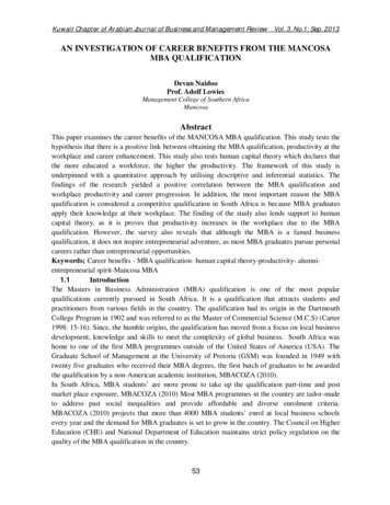
Metal AM Product VariabilityPost-Processing As-built parts also show the presence of voids (left micrograph) caused bylow power, high scan rate, attenuated laser (from fogging of the laser lens,for example), or in the case shown below, spatter (molten ejecta) falling onsurface during build. After heat treatment and/or HIP, such lack of fusion(LOF) defects are closed (right micrograph):Lack of fusion defect caused by spatterLack of fusion defect after HIPSource: Brown, A., Jones, Z. Tilson, W., Classification, Effects, and Prevention of Build Defects in Powder-bed Fusion Printed Inconel 718,NASA Marshall Space Flight Center, 2016.
Processing and Post-ProcessingRelative to AM part life cycledesigndesignallowablesPROCESSINGpart tpart NDEpost-processedpart NDEPOST-PROCESSING
Section 2Additive Manufacturing,Examples of Aerospace Applications
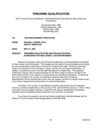
Metal Aerospace AM PartsExample 1NASA MSFC rocket injectors made bytraditional means took more than ayear to make, but with AM took less than fourmonths, resulting in a 70% reduction in cost. Using traditional manufacturing methods, 163 partsare made, which must then be assembled by welding. With AM, only 2 parts are needed, saving time and 28-element Inconel 625 fuel injector built usingan laser powder bed fusion (L-PBF) processmoney, and allowing engineers to enhance rocketengine performance while being less prone to failure. Liquid Rocket Engines with 100 to 35,000 lbf thrusthave been manufactured with AM hardware, includinginjectors, injector faceplates, regeneratively-cooledcombustion chambers and nozzles, gas generators,preburners, and augmented spark igniters.Hot fire test using L-PBF .2018-4625
Metal Aerospace AM PartsExample 1(cont.)SLM Injectors fabricated and tested at 625
Metal Aerospace AM PartsExample 2NASA MSFC has also built channel-cooledcombustion chambers using L-PBF, but thatuse bi-metallic additive and hybrid techniques. The materials used vary from Inconel 625 and 718,Monel K-500, GRCop-84, and C18150 metal alloys. The thrust chambers designs tested ranged from 200 to1,400 psia in a variety of propellants and mixture ratios,producing 1,000 to 35,000 lbf thrust. Workhorse chamber liners, bi-metallic chambers,augmented spark igniters, and larger scale channel-coolednozzles have also been 625LOX/methane Inconel and GRCop-84chamber throat sections and hot-fire testing
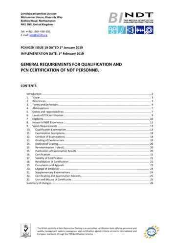
Metal Aerospace AM PartsExample 3 Engineers successfullyhot-fire tested a heritage RS-25 rocketengine retrofitted with a pogo accumulator,which regulates LOX movement duringflight to prevent destabilizing vibrations: Simpler: over 100 welds eliminated More affordable: costs reduced by nearly 35%and production time by more than 80% Welds require inspection and possiblerework, and are points of possible failure;therefore, eliminating them reducesproduction costs and increases partreliability.A technician for NASA's RS-25 prime contractorexhibits the pogo accumulator (top and middle),which was subsequently hot-fire tested ture-sls-engine-costs
Metal Aerospace AM PartsIn Summary In addition to reductions in Design, Development, Test and Evaluation (DDT&E)time (7-10 years to 2-4 years), hardware lead time (3-6 years to 6 months), andcosts (order-of-magnitude reductions possible), part counts can be dramaticallyreduced:Reduction in parts count for a rocket .nasa.gov/20160004218.pdf
Section 3Governing Standards
Definition of Additive Manufacturing(NASA-STD-6016A Standard Materials and ProcessesRequirements For Spacecraft)Additive Manufacturing: Any process formaking a three-dimensional object from a3-D model or other electronic data sourceprimarily through processes in whichsuccessive layers of material are depositedunder computer control.
NASA-STD-6016AStandard Materials and ProcessesRequirements For Spacecraft§ Guidelines documents and standards for additive manufacturing are indevelopment at this time. The requirements of this NASA Technical Standardon M&P controls, materials design values, metallic and nonmetallic materials,and nondestructive inspection apply to hardware manufactured by additivetechniques, just as they do for traditional manufacturing techniques. For nonstructural, nonmetallic 3-D printed hardware, controlled and verifiedprocesses are essential; but other M&P aspects like flammability, toxicoffgassing, and vacuum outgassing also apply, just as for any othernonmetallic material. When structural hardware is manufactured by additive manufacturingtechniques, a manufacturing and qualification plan shall be submitted toNASA and approved by the responsible NASA M&P and design organizations.§ guidance(italics) and requirements excerpts from NASA-STD-6016A
NASA-STD-6016AStandard Materials and ProcessesRequirements For Spacecraft§ Key aspects of producing structural metallic hardware by additivemanufacturing techniques, such as direct metal laser sintering (DMLS) andselective laser melting (SLM), include proper development of structuraldesign values and controlled processes, although other requirements, suchas stress-corrosion resistance and corrosion control, also apply. Verificationof appropriate process control should include first article inspection to verifyproper material properties and macro/microstructure and mechanicalproperty testing of integrally manufactured specimens from each hardwareunit.§ guidance(italics) excerpts from NASA-STD-6016A
Active Standards for AM within NASA:MSFC-STD-3716 & c3717baseline.pdfReleased Oct. 18, 2017
Developing NASA Agency-Level StandardsMSFC-STD-3716NASA-STD-603X65 AMRsMSFC-SPEC-3717AMStandard forCrewedNASA-STD-603XAMStandard forUn-CrewedNASA-STD-603XPCQRs for:Process definitionQMPsAMStandard forAeroNASA-SPEC-603XPCQRs for:Equipment and facility process controlAM Spec forEquip andFac.
MSFC-STD-3716 Outline General requirements govern theengineering and production practiceand are paralleled by a QualityManagement System (QMS). Process control requirements providethe basis for reliable part design andproduction and include: qualified metallurgical processes (QMPs)equipment controls (ECP)personnel trainingmaterial property development Part Production Control requirementsare typical of aerospace operationsand must be met before placing apart into service.
MSFC-STD-3716/MSFC-SPEC-3717 OutlineFoundational Process Controlsprovide the basis for reliable partdesign and productionPart Production Controls are typical ofaerospace operations and includedesign, part classification, preproduction and production controls
Key Quality Assurance ProductsKey Quality Assurance Products Quality Management System, AS9100 (QMS)Additive Manufacturing Control Plan (AMCP)Equipment and Facility Control Plan (EFCP)Training Plan/ProgramQualified Metallurgical Process Records (QMP)Statistical Process ControlsQualified Part Process (QPP)Production Engineering ControlsProduction Process ControlsAcceptance Testing Witness Testing NDE
Key Quality Assurance Products Quality Management System, AS9100 (QMS) [AMR-4] The CEO shall ensure a QMS conforming to SAE AS9100, Quality Management Systems –Requirements for Aviation, Space and Defense Organizations, or an approved equivalent, is in placeand active at all entities involved in the design and production of L-PBF hardware Additive Manufacturing Control Plan (AMCP) [AMR-3] The CEO responsible for the design and manufacture of L-PBF hardware shall provide anAMCP that accomplishes each of the following:a) Documents the implementation of each of the requirements of this MSFC Technical Standard.b) Documents and provides rationale for any tailoring of the requirements of this MSFC TechnicalStandard.c) Documents the methods used to control compliance with these requirements by subcontractorsand vendors.d) Provides for complete governance for the implementation of L-PBF such that, once approved bythe procuring authority, the AMCP becomes the document used for verification of L-PBFrequirements.
Key Quality Assurance Products Equipment and Facility Control Plan (EFCP) [PCQR-24] An Equipment and Facility Control Plan (EFCP) shall be developed andmaintained within the QMS that addresses, at minimum, the implementation of therequirements of L-PBF equipment and facility control of Section 4.5 and itssubsections. Examples of EFCP Controls Feedstock Storage and Handling Contamination and FOD control Computer and Data Security Operational Procedures and Checklists Configurational Management of AM machines and equipment Maintenance and Calibration Machine Qualification
Key Quality Assurance Products Training Plan/Program [PCQR-45] An active operator training program shall be defined, maintained, andimplemented to meet the following objectives:a) Provide a consistent framework for training and certification requirementsb) Provide clear delineations of abilities and responsibilities associated withgranted certificationsc) Provide operators with all necessary skills, knowledge, and experience toexecute the responsibilities of their certification safely and reliablyd) Provide for operator evaluations that demonstrate adequacy in skills,knowledge, and experience to grant certifications to personnel, ensuring onlyproperly trained and experienced personnel have appropriate certificationse) Incorporate content regarding the importance, purpose, and use of the QMS forall certifications.
Key Quality Assurance Products Qualified Metallurgical Process (QMP) Records Begins as a Candidate Metallurgical Process Defines aspects of the basic, part agnostic, fixed AM processincluding:1. Feedstock2. Fusion Process3. Thermal Post-Process Qualification of candidate process through rigorousevaluations Enabling concept Machine qualification and re-qualification Process control metrics, SPC Design valuesSource: Fraunhofer IWU
Key Quality Assurance Products Statistical Process Controls Acceptance Criteria Derived from PCRD Acceptance criteria forwitness testsProcess ControlReference Distribution
Key Quality Assurance Products Qualified Part Process (QPP) Pre-Production Article Evaluation Powder removal, dimensions, surface quality, mechanical properties, internal quality,microstructure, high risk areas Additive Manufacturing Readiness Review Stakeholder review of production engineering record, part drawing, approved PPP, PreProduction Article Report If successful, AMRR demarcates when part process is qualified Complete part manufacturing process is locked for production No changes without re-qualification or proper disposition QPP state is documented in the Quality Management System Production Engineering Controls Production Process Controls Manage and document Production
Key Quality Assurance Products Acceptance Testing Witness Testing [AMR-26] Witness sampling for each L-PBF buildshall be described in the PPP, including sampletypes, designs, and quantities, their layout inthe build volume, test methods, and acceptancecriteria. Required for all builds, varies with Part Class Differing Stand Alone versus ContinuousProduction criteria NDE [AMR-54] All L-PBF parts shall receive comprehensive NDE for surface and volumetric defectswithin the limitations of technique and part geometry unless otherwise substantiated as partof the Integrated Structural Integrity Rationale per section 6.1.4.Focus of next section: AM Defects and NDE
AM QA OpportunitiesThere are two primary opportunities to ensure AM reliability forqualification and certification rationale:1. In-Process Controls (Control what you do) Qualify the AM Process and the AM Part Process Understanding fundamentals Recognizing the process failure modes (pFMEA) Identifying observable metrics and witness capabilities Meticulous process scrutiny through ocessControl(SPC)QualifiedPart Process(QPP)MaterialPropertiesSuite (MPS)2. Post-Process Evaluation (Evaluate what you get) Non-destructive Evaluation, Proof testing Post-build process monitoring data evidencePart reliability rationale comes from the sum of both in-process and post-processcontrols, weakness in one must be compensated in the otherRationaleforQualifiedAM parts
Nadcap PBF QA ResourcesRecently published:AC7110/14 Audit Criteriafor Laser and ElectronBeam Metallic PowderBed AdditiveManufacturing(Used as supplement to PRI AC7110) Good list of audit questionsfor suppliers Will not address all issuesfrom MSFC-STD-3716, butprovides excellent, detailedchecklist and information.
Section 4Additive Manufacturing DefectsAnd NDE Challenges
Defects – Effect of Process §AM Defects: Effect of Process Certain AM flaws (for example,voids and porosity) can occurin most or all AM parts (nonprocess specific), and can becharacterized using existingmethods for welded or castparts. Other AM flaws (for examplelayer, cross layer, unconsolidatedand trapped powder) are uniqueto PBF and new or better NDEdetection methods are needed.Developnew orbetterNDEmethods§ ISO TC 261 JG59, Additive manufacturing – General principles – Nondestructive evaluation of additive manufactured products, under development.Note: DED Directed Energy Deposition, PBF Powder Bed Fusion, unconsolidated powder is synonymous with lack of fusion (LOF) flaws
AM Defects General PBF and DED defects - interested in lack of dimensional accuracy orwarping, inclusions, process-induced porosity, gas-induced porosity, andcracks (potential structural implications or out-of-tolerance part):dimensions/warpingPBF gas porosityinclusionsDED gas porosityPBF process voidPBF crackPBF delamination
AM Defects Specific PBF defects – interested in skipped layer/stop-start flaws, lack offusion (LOF), and trapped powder due to potential structural implications orout-of-tolerance part:skipped layer/stop-start(layer defect)Vertical LOF(cross layer defect)trapped powder
Bulk Defects Causing MechanicalProperty DegradationInclusion – Foreign material either non-metallic or metallic incorporated intothe deposited material. Inclusions are typically oxides, nitrides, hydrides,carbides, or a combination thereof and may or may not have some coherencywith the surrounding material.CAUSES – Formed due to contamination of the chamber gas, input material or dirty buildchamber.EFFECTS – Inclusions can serve as stress concentrators and the locus for catastrophic partfailure (degraded mechanical properties).Micro-CT scan (left)Energy-dispersivex-ray spectroscopy(EDS) mapping ofaluminum oxideinclusions in anUNS N07718 part(MSFC)and optical scan offracture surface(right) of a Ti6-4tensile specimenshowing the locus offailure coincidingwith an inclusion(MSFC)
InclusionsPowder characterization – ASTM F3049 defines feedstock characteristics which areconsidered useful to assure the confidence in the selected powder and in the final PBF partproperties. Among those characteristics are the particle size and its distribution, themorphology (sphericity), the chemical composition, the flow characteristics, and the density ofthe powder. X-ray CT is used to characterize the defect population, namely inclusions.X-ray CT slice image of the powdershowing high density inclusions,visible as bright particleshttp://www.mdpi.com/1996-1944/10/5/522SEM images of the fracture surface of a tensile specimen inthe Z orientation showing close-up views of cracked inclusion(left) and an inclusion (right) with a brittle appearance.
Bulk Defects with Variable Effects(may be significant or severe)Void – A general term encompassing both irregularly-shaped or elongatedcavities (process-induced porosity), and spherically-shaped cavities (gas-inducedand keyhole porosity). These cavities can be empty (gas) or filled with partiallyor wholly unfused powder (LOF). Voids are distinct from intentionally addedopen cells to reduce weight.CAUSES – See LOF, gas porosity, and keyhole porosity.EFFECTS – Results in a less than fully dense part; at asufficient quantity, size and distribution voids candegrade mechanical ts-in-powder-bed-fusion-technology
Bulk Defects with Variable Effects(may be significant or severe)Lack of Fusion (LOF) – A type of process-induced porosity specific to unsintered(fully-melted) parts. Can be an empty cavity or contain unconsolidated powder.LOF typically occurs in the bulk, making its detection difficult. Like voids, LOF canoccur across single (horizontal LOF) or multiple layers (vertical LOF).CAUSES – 1) incomplete melting of a depositedlayer onto a previously deposited solidified layer,2) inadequate penetration of a deposited layer intothe previous layer, 3) improper hatch spacingbetween two successive passes, or 4) "stop/start"process anomalies, caused by interruption offeedstock supply or short feed. 1) and 2) arecaused by low power/fast scan rate settings.EFFECTS – Like other forms of porosity and voids,LOF can cause a part to be less than fully dense, ordegrade mechanical properties.Vertical lack of fusion defects caused byhatch spacing set too wide (MSFC)
Lack of Fusion (LOF)Defects (e.g., lack of fusion, voids) detected by micro-CT, need to be linked toprobabilistic models for fracture, fatigue, and lifing predictions.Fracture surface of as-built EBM Ti-6Al-4V tested infatigue showing LoF defects perpendicular to thebuild directionMetallographic cross-section and fracture surfaceof as-built EBM Ti-6Al-4V tested in xt/u2/1035268.pdf
Keyhole PorosityKeyhole Porosity, grain size, and surface roughness are all correlated with laseror electron beam power and velocity:(a) Power-Velocity (P–V) map for electron beam (Arcam) processed Ti-6Al-4V showing regimes ofgood quality beads as well as size of beta grains. (b) Inset shows different scales of surfaceroughness of multi-layer beads produced via laser-based techniques at different P–V 007/s11837-015-1810-0M. Seifi, D. Christiansen, J.L. Beuth, O. Harrysson, and J.J. Lewandowski, Ti-2015: The 13th World Conference on Titanium (Wiley, 2016).
AM Defects: Classes and Subclasses§ ASTM WK47031, new Draft Standard – Standard Guide for Nondestructive Testing of Metal Additively Manufactured Aerospace Parts After Build,ASTM International, West Conshohocken, PA (in ballot).
AM Defects: Effect on NDE Selection§ ASTM WK47031, new Draft Standard – Standard Guide for Nondestructive Testing of Metal Additively Manufactured Aerospace Parts After Build,ASTM International, West Conshohocken, PA (in balloting).
USAF/AFRL-RX-WP-TR-2014-0162 NDE of Complex AM StructuresUSAF/NDE of Complex AM StructuresAFRL-RX-WP-TR-2014-0162Contact: Evgueni Todorov (EWI) Early results on NDE applicationto AM are documented. Report has a ranking systembased on geometric complexityof AM parts to direct NDEefforts. Approach laid out for futurework based on CT and PCRT andother NDE wnload?doi 10.1.1.831.6412&rep rep1&type pdf
USAF/AFRL-RX-WP-TR-2014-0162 NDE of Complex AM StructuresEffect of AM Part Complexity on NDEAFRL-RX-WP-TR-2014-0162 Most NDE techniques can be used for Complexity Group§ 1 (Simple Toolsand Components) and Group 2 (Optimized Standard Parts):12§ Kerbrat, O., Mognol, P., Hascoet, J. Y., Manufacturing Complexity Evaluation for Additive and Subtractive Processes: Application to Hybrid Modular Tooling,IRCCyN, Nantes, France, pp. 519-530, September 10, 2008.
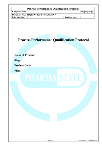
USAF/AFRL-RX-WP-TR-2014-0162 NDE of Complex AM StructuresEffect of AM Part Complexity on NDEAFRL-RX-WP-TR-2014-0162 Only PCRT, CT, and LT can be used for Complexity Group§ 4 (Design-toConstraint or Topology Optimized Parts) and Group 5 (Lattice Structures):45§ Kerbrat, O., Mognol, P., Hascoet, J. Y., Manufacturing Complexity Evaluation for Additive and Subtractive Processes: Application to Hybrid Modular Tooling,IRCCyN, Nantes, France, pp. 519-530, September 10, 2008.
USAF/AFRL-RX-WP-TR-2014-0162 NDE of Complex AM StructuresEffect of AM Part Complexity on NDEAFRL-RX-WP-TR-2014-0162NDE options fordesign-to-constraint partsand lattice structures:PCRT, CT/mCT, and LT
Main FindingsNASA/TM-2014-218560 NDE identified as a universal need spanning all aspects of additivemanufacturing. NDE identified as the only effective way to ensure AM parts meetnecessary NASA requirements. NDE and materials experts must develop techniques to characterizedefects, determine their effect on performance, learn how to reliablydetect them to screen for defects, in order to qualify parts for use.NDE
Top Level NDE ChallengesNASA/TM-2014-218560 Deeply embedded flaws and hidden internal features can be difficult todetect or characterize or perform metrology on. High part anisotropy with 2D planar high aspect ratio (a/c (a is the crackdepth and c is the half-surface length) defects perpendicular to Zdirection can be difficult to detect or characterize. Rough as-built surfaces interferes with surface-sensitive NDE methodsuch as PT (penetrant testing) and ET (eddy current testing). Critical flaw types, sizes and distributions not defined for AM parts (NDEaccept/reject criteria are needed). Lack of written procedures (standards for NDE of AM hardware areneeded).
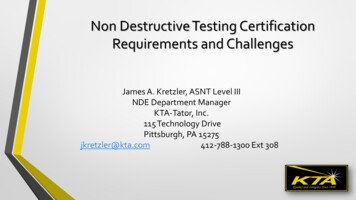
NASA-STD-5009 NDE RequirementsFracture Critical Metal Hardware Must meet the NDE requirements given in NASA-STD-5009§, but the 90/95Probability of Detection (POD) crack sizes generally will be inappropriate:NASA-STD-5009 crack geometries AM crack geometries While diagram (left) can beused, do 5009 crack sizes(next slide) apply? What about other AM flaw types? porosity/voids V-LOF, H-LOF gas keyhole? inclusions surface roughness§ NASA-STD-5009, Nondestructive Evaluation Requirements for Fracture-Critical
Welcome to Qualification & Certification of Additive Manufactured (AM) Parts for . In PBF, metal powder is fused layer-by-layer using a high-energy electron or laser beam. After one layer is fused, a new powder layer is spread on the newly solidified . Monel K-500, GRCop-84, and C18150 metal alloys.