Transcription
Kabarak Journal of Research & InnovationVolume 3 Number 1 (2015)ISSN 2305-784XDesign of a Low-Cost Microcontroller-Based Lightning Monitoring DeviceKamau M. Gilbert1* Kang’ethe M. Samuel1, Kamau I.Stanley1, Giesen Nick21Faculty of Engineering, Department of Electrical & Electronic Engineering Department, JKUAT, P.OBox 62000-00200, Nairobi-Kenya2Faculty of Civil Engineering and Geosciences, Water Management Department, Delft University ofTechnology, Postbus 5 2600 AA Delft, The Netherlands.Submitted: 29th July 2014; Published: 3rd March 2015AbstractLightning data is not only important for environment and weather monitoring but also for safety purposes.A device that monitors and keeps track of occurrences of lightning strikes has been developed. Acommunication interface is established between the sensors, data logging circuit and the microcontroller.The digital outputs of the lightning sensor and data from GPS are processed by the microcontroller andlogged onto an SD card. The interface program enables sampling parameters such as distance from thelightning strike, time of strike occurrence and geographical location of the device. For archiving andanalysis purposes, the data can be transferred from the SD card to a PC and results displayed using agraphical user interface program. Data gathered shows that, the device can track the frequency andmovement of lightning strikes in an area. The device has many advantages as compared to other lightningsensor stations in terms of huge memory, lower power consumption, small size, greater portability andlower cost. The device shall be used in designing lightning network.Key words: Lightning monitoring, Microcontroller, Data logger, SensorIntroductionScientific research requires collection of data in order to study, monitor, analyze describe and understanda particular processes. In the area of lightning, collecting lightning data is complicated by the nature ofthe strikes. Lightning strikes have a nominal duration of 20 to 50 microseconds, and are typicallyseparated in time by 20 to 100 milliseconds. A flash generally comprises 2 to 4 strokes, but may containas few as one and as many as ten or more strokes (Cummins, Murphy, Bardo, Hiscox, & Pyle, 1998). Thisputs a lot of demand on timing. The most advance lightning monitoring systems are the lightningnetworks, commonly used to gather lightning information over a wide area. Kenya and most developingcountries do not have lightning networks. This is because of the complexity associated with design,installing and maintenance of lightning networks which makes them very expensive (Dowd, et al., 2000).In recent years, it has been possible to produce smaller and cheaper lightning sensors that can beintegrated with the computing technology. Moreover, growth in technology has made it possible tointegrate communication networks with computing technology.This paper aims to build a low cost yet reliable lightning detector. The detector shall be capable ofcapturing and recording data on the position of the sensor and the times at which lightning strikes arecaptured. The lightning sensor of the detector shall capture lightning events and reject any form ofdisturber signals. The GPS sensor shall capture details on location of the sensor and the times when thestrikes occurs. The digital output of the sensors shall be processed by the controller and data logged ontoan SD card. The data can be analyzed to understand the frequency and movement of lightning strikes inan area.*Corresponding author: kamau.gilbert@students.jkuat.ac.keKabarak j. res. innov. 3 No. 1, 32-40 (2015)
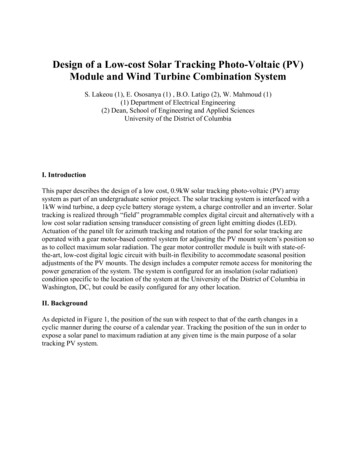
Kamau et al.2Lightning Systems and sensingThere exists both orbital and ground based lightning monitoring systems. On orbital satellites, there areLightning Imaging sensors (Mach, et al., 2007) and optical transient detectors (Christian, et al., 2003).There is high cost associated with powering, launching and maintaining orbital lightning systems.Use of ground based lightning networks is the most advanced method of gathering lightning data.Lightning networks consist of multiple sensors and communication systems that transmit the lightningdata to a central place. At the central place, the data is processed and distributed to users (Cummins,Kridder & Malone, 1998). There is high cost associated in design, implementation and maintenance of thenetwork. As a result, many developing countries do not have a lightning network. At least, the sensorstation requires AC voltage of 240 volts to maintain their operation.During lightning flash, there is rapid acceleration of charge from lightning channel which produceselectromagnetic radiations known as sferics in all frequency bands. These electromagnetic pulses arepropagated away from the lightning channel and get directed within the Earth-ionosphere (Wood & Inan,2004). The energy of radiations can be detected by sensors to determine the presence of a lightningactivity. The energy of sferics gets attenuated with time. Attenuation is dependent on the frequency of thesferics. The lowest frequencies travel long distances while the highest frequencies are attenuated within ashort distances.Equation 1 gives the inverse square law applicable to all forms of electromagnetic radiations. It impliesthat the power of any electromagnetic radiations is inversely proportional to the distance of radiatingsource (Petty, 2007). The lightning sensor determines the distance to the lightning source by assuming anaverage strength and comparing that with the measured energy (Austria Microsystems, 2012).(1)Proposed SystemIn recent years, it has been possible to produce smaller and cheaper sensors that can be integrated with thecomputing technology. Moreover, growth in technology has made it possible to integrate communicationnetworks with computing technology. Such networks would make it possible to have cheap and low-costsolutions for tracking individual incidents (Qixin, 2008.)The fact that both sensors and network can beintegrated on a computing environment makes it possible to have cheaper systems that can convenientlymonitor and record lightning activities. The proposed station uses a maximum of 9V DC which willsignificantly cuts the power cost when deployed in a lightning network.The System CircuitUsing Arduino, a Serial Peripheral Interface (SPI) communication protocol is established which facilitatescommunication of the lightning sensor and the data logging circuit. SPI is a high-speed, full-duplex,synchronous communication bus (Liul & Wang, 2011). In order to save the space on the soldering boardand the chip ports, only four lines are taken by the SPI ports. As indicated in Figure 1 below, the sensorstation works using the Master-Slave full duplex mode with the processor as the master device and twoslave device. The protocol requires four lines whose components are SCK (clock), SDI (data in), SDO(data out), and SS (Slave select). An additional serial Transistor-Transistor logic (TTL) communicationprotocol is established between the GPS sensor and the processor.Kabarak j. res. innov. 3 No. 1, 32-40 (2015)
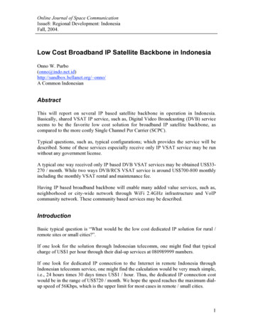
Kamau et al.3PROCESSOR(ARDUINO)CLOCK (SCK)MOSIAS3935 LightningSensorMISO(SPI Master)RXSS(SPI Slave)TXSD CARD Logger(SPI Slave)GPS SENSORFigure 1: SPI with controller, Lightning Sensor, GPS sensor and the Data logging CircuitWhen the SPI master wants to send data to a slave, it will pull the SS line low for selecting slave. It thenactivates the clock signal which is usable between the master and the slave at same time. The mastertransmits the data to the MOSI (master’s SDO and slave’s SDI) line and receives the data from the MISO(master’s SDI and slave’s SDO) line at the time. SPI is a serial communication protocol, that data istransmitted bit by bit. The clock pulse is provided by SCK. SDI and SDO use this pulse to make the datatransmission. Data output is through the master’s SDO line at the falling or rising edge of the clock, andcan be read by slave in the falling or rising edge. So 8-bit data transfer need at least 8 times the clocksignal changes (Ananthula, Kumar, & Bhandari, 2012). The code for the integrated system is availableupon request.ProcessorThe main component here is the ATmega1280 microprocessor, which is equipped with 128 Kb of flashmemory and processing speed of up to 16 MHZ. The microprocessor not only controls the system, butalso synchronizes all the module operations. The microprocessor is based on an Open Source Hardwareproject called Arduino. Arduino comprises of a programmable microcontroller development platform, aprogramming development environment for creating custom microcontroller software, and expansioncapability through add-on boards (Fisher & Gould, 2012). All electronic and circuit-board componentspecifications, including the programming software, are open-source and freely available for anyone tomodify or use. Additionally, Arduino boards come with a library for interfacing SPI. The Arduino isprogrammed using Arduino IDE software that utilizes C language.Lightning SensorThe AS3935 is a fully integrated programmable lightning sensor IC that detects the presence andapproaching hazardous lightning activity in the vicinity. It provides estimation on the distance to the headof storm, where the leading edge of the storm is defined as the minimum distance from the sensor to theclosest edge of the storm. (AS3935 Franklin Lightning Sensor IC datasheet, 2012). Figure 2 below showsthe block diagram of the AS3935. The external antenna amplifies and demodulates the received signal. Itis connected directly to the Analog Front-end (AFE). The watchdog monitors the output of the AFEcontinuously. In the event of an incoming signal, it alerts the integrated lightning algorithm block. Theincoming signal is validated by the lightning algorithm block. This is done by checking the incomingKabarak j. res. innov. 3 No. 1, 32-40 (2015)
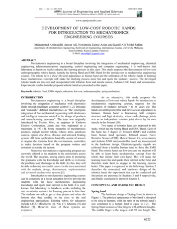
Kamau et al.4signal pattern and calculating the signal energy. Upon verification, AS3935 provides the processor unitwith a distance estimate to the head of the storm. The demodulated signal, can be distinguished if it isman-made disturber or true lightning signal by the lightning algorithm block. If the signal received isclassified as a disturber the event is rejected and the sensor goes back to listening mode. However, if thesignal is identified to be a true lightning strike, the statistical distance estimation block estimate thedistance to the head of storm.Figure 2: Block diagram of AS3935AS3935 has three operating modes; power-down mode, listening mode and signal verification. In thepower-down mode, the power is switched off and the current consumption is minimum. In the listeningmode, noise floor generation, the watchdog, the AFE, the TRCO, the bias block and the voltage regulator(if it is enabled) are running. The sensor enters signal verification mode whenever dynamic activities arepicked by antenna. The incoming signal has to cross a certain threshold for signal verification mode to beactivated. The IC leaves this mode if the analysis of a single lightning event is finished or if the incomingsignal is classified as a disturber. If the received signal is classified as lightning event, energy calculationis done and AS3935 provides distance estimation. If the received signal is classified as disturber, AS3935automatically goes back to the listening mode and an interrupt will be generated.GPS sensorWith the instant position of high-speed satellite as the known initial data, the basic principle of GPSpositioning is to adopt the spatial distance intersection method to determine the location of the points tobe measured (Huang, et al., 2013). When the GPS receiver obtains longitude, latitude, altitude, time andspeed information of geographic location through GPS positioning solution method, distributesinformation in a distinctive data format so that the calculated navigation information can be transmitted tothe peripherals. GPS is equipped with a serial port (TTL or RS-232 level) to enable the transmission.The GPS breakout shown in figure 3 is built around the MTK3339 chipset, a high-quality module that cantrack a maximum of 22 satellites on 66 channels. It has a receiver with sensitivity of -165 dB whentracking, and a built in antenna. It can do up to 10 location updates a second for high speed, highKabarak j. res. innov. 3 No. 1, 32-40 (2015)
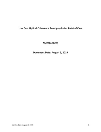
Kamau et al.5sensitivity tracking or logging. The power usage is low, only 20 mA during navigation. The GPS moduleis used to pick data on date, time, altitude and location.Figure 3: GPS SensorData Logging CircuitAn SD data logging shield is connected to the microcontroller to facilitate storage the sensor’s readings.An SD card is inserted to the card slot of the shield in figure 4. The interface between the microcontrollerand the SD card holder is SPI. The data received is stored in comma-separated values (CSV) files.Kabarak j. res. innov. 3 No. 1, 32-40 (2015)
Kamau et al.6Figure 4 Data Logging ShieldTime Keeping CircuitsThe system records time from two independent circuits that runs simultaneously. There is the GPS timeand real-time clock (RTC). The most accurate time is from GPS which is picked from satellites. The RTCchip, attached to the SD card shield, provides less accurate time but is powered by an external coin batterywhich ensures that time track is kept even when the GPS is not picking satellite signals, or when thesensor station is not powered. Both times are captured whenever a signal is detected by the lightningsensor.Result and DiscussionThe functionality of the sensor station is analyzed by gathering lightning data using two sensor stationsplaced on the same location. Table 1 shows the data that was captured at Oraimutia village on 3 rd May2014.Table 1 Comparison of strike distance measurements of two sensors placed on the same locationSENSOR STATION 1SENSOR STATION 2GPS timeDistance (km)GPS timeDistance (km)6:10:25 PM186:10:25 PM206:11:23 PM186:21:31
This paper aims to build a low cost yet reliable lightning detector. The detector shall be capable of capturing and recording data on the position of the sensor and the times at which lightning strikes are captured. The lightning sensor of the detector shall capture lightning events and reject any form of disturber signals. The GPS sensor shall capture details on location of the sensor and the times when the