Transcription
Introduction to Reservoir SimulationDr Panteha Ghahri9th May 2018 OGA 2018This presentation is for illustrative purposes only. The OGA makes no representations or warranties, express or implied, regarding the quality, completeness or accuracy of the information contained herein. All and any suchresponsibility and liability is expressly disclaimed. The OGA does not provide endorsements or investment recommendations. Oil and Gas Authority is a limited company registered in England and Wales with registered number09666504 and VAT registered number 249433979. Our registered office is at 21 Bloomsbury Street, London, United Kingdom, WC1B 3HF
SE-06 Production OptimisationImplementation Guide 2.1 Reservoir, wells and plant technical limits“Understand the recovery technical limit and current predicted recovery, andthen evaluate and select future recovery options (new wells, improved oilrecovery, enhanced oil recovery, etc) to maximise economic recovery”Static and Dynamic Reservoir models are key elements for evaluating andselecting any future recovery options (infill wells, improved oil recovery,enhanced oil recovery)
SE-06 Production OptimisationImplementation Guide2.2 Reservoir management plans“Amodel (static and dynamic) describing the distribution andcharacterisation of hydrocarbons in place and reserves”Static and Dynamic Reservoir models are key elements of agood reservoir management program.
Outline Reservoir engineering techniques for forecast, reserves estimationand reservoir behaviour prediction Analogues Decline curves analysis Material Balance Reservoir simulation Reservoir simulation background Model purposes Model contents vs. complexity Reservoir model elements
Outline Probability and Determinism (reservoir model components)Static modelGridRock property modellingDynamic modelMajor laws used in reservoir simulationNumerical techniques in reservoir simulationScale/UpscalePseudo/ Effective propertyBlack oil model/Compositional model
Outline Reservoir simulation taskHistory matchUncertainty handlingField applications
Modelling techniques through the field life Analogues Decline curves analysis Material Balance Reservoir simulation
Use of Analogues for RF estimation Analogues uses forbenchmarking of mature fields For RF estimation for prospectevaluation
Decline curves analysis Basic tool forecasting productionfrom a well or well group Sufficient production to establisha decline trend
Material Balance An alternative, largely independent method of estimating the originalhydrocarbons in-place (OOIP and OGIP) Sufficient production data
Reservoir Simulation OGA 2018This presentation is for illustrative purposes only. The OGA makes no representations or warranties, express or implied, regarding the quality, completeness or accuracy of the information contained herein. All and any suchresponsibility and liability is expressly disclaimed. The OGA does not provide endorsements or investment recommendations. Oil and Gas Authority is a limited company registered in England and Wales with registered number09666504 and VAT registered number 249433979. Our registered office is at 21 Bloomsbury Street, London, United Kingdom, WC1B 3HF
Reservoir simulation A tool developed by combingphysics, mathematics, reservoirengineering, and computerprogramming for predictinghydrocarbon reservoir performanceunder various operating strategies Gain insight into the recoveryprocesses of a reservoirAdvanced Petroleum Reservoir Simulation, M.R. Islam
Reservoir Simulation Reservoir simulation leading toprediction of reservoir behaviour Reservoir simulation studies arevery subjective and vary fromsimulator to simulator. Currently available simulatorsonly address a very limitedrange of solutions for aparticular reservoir engineeringproblem.
“Garbage in Garbage out (GIGO)”A computer program based onthe mathematical model needsinput!Required reliable data?No simulator can replace reliabledata or the brain of the user.
History of reservoir simulation 1950 – 1970, Two/Three dimensions, simple geometry, black oilfluid, well conning, multiple wells 1970 – 1980, Compositional, thermal, miscible 1980 – 1990, Complex well management, fractured reservoirs,special gridding at faults, graphic interface 1990s –Advanced GUIs, integration with geo-modelling,geomechanics, parallel computer techniques, local gridrefinement
Reservoir model purposes Estimate field performance Development Planning Visualisation Volumetric calculation Well planning Probabilistic models Input to seismic modelling
Model contents vs. complexity “In reservoir simulation,the question is notwhether, but how and howmuch. The complexity ofthe questions being asked,and the amount andreliability of the dataavailable, must determinethe sophistication of thesystem to be used.”Based on Underhill 1998
Model contents vs. complexity Build a model?Reservoir Model Design, Mark Bentley
Reservoir simulation elements Geological description Probabilistic or deterministic Fluid Type Black oil / Compositional Reservoir depletion mechanism
Probabilistic and DeterministicDeterministicProbabilistic All necessary data is known before Can tell exactly what is going tohappen, once the system starts. Example. Conversion between ftand meter is deterministic The process of calculating theoutput is deterministic process Element of chance is involved Don’t see exactly when it willoccur, but the possibility is known Example. Roll a die until it comesup ‘3’. Know that in each roll, a ‘3’ willcome up with probability 1/6.
Reservoir models(Probabilistic and Deterministic components) All reservoir modelselements are a combinationof probabilistic anddeterministic components3D geology and reservoir modelling in oil industry: Geologic model construction by integration of sedimentology, sequence stratigraphyseismic geomorphology, exploration geophysics and geostatistics, Osamu Takano, Journal of the Geological of Japan, Jan 2013
Static model Geocellular modelling The process of generating a model of the subsurface The physical properties of the reservoir are stored at the grid point Steps Define a proper GRIDStructure modellingStratigraphic modellingLithological modellingPetrophysical modelling
Grid The aim of gridding in reservoir simulation is to turn thegeological model of the field into a discrete system which the fluidflow equation can be solved. Common grid co-ordinate system Cartesian Cylindrical
Grid How we divide or discretize, geologicalmodel into divisions of ΔX, ΔY, ΔZ. Wealways “Shup-up” the reservoir into blockand then we model the block to block andthen we model the block to block. Temporal Discretisation This is the process of dividing up the timestep into divisions of ΔtHeriot Watt University, Reservoir simulation course
Grid Oil and gas reservoirs structure is a set of geological horizons representingbedding planes Two related issues are involved in choosing a grid for reservoir simulation: Accuracy with which the geological description of the reservoir is matched Discretisation of the flow equationsHeriot Watt University, Reservoir simulation course
Rock Property modelling Given difficulty of measuringrock properties, it is commonto use geostatical methods tomake realisation ofpermeability, porosity andwater saturation.
Dynamic model Once the static modellinghas been completed, thenext step is buildingdynamic model and validateit using the production dataand well test. This model is used forforecasting and fielddevelopment planning
Major laws used in reservoir simulation Conservation of mass Conservation of momentum Conservation of energy
Mass Conservation Flow equations for flow in porous materials are based on a set of mass,momentum and energy conservation equations, and constitutive equationsfor the fluids and the porous material involved.
Conservation of momentum Conservation of momentum is governed by the Navier-Stokesequations, but is normally simplified for low velocity flow inporous materials to be described by the semi-empirical Darcy'sequation, which for single phase, one dimensional, horizontalflow is:
Flow Equations in Reservoir Models
Mathematical solution Exact analytical solution not exist Mathematical techniques used Homogenization, volumetric average Numerical methods e.g. finite difference, finite volume, finite elementsmethods
Numerical Methods in Reservoir Simulation Pressure equation would be a set of linear equations if thecoefficients were known at the current time step (n). Hence, canbe solve as “linear system of equations” by time-lagging thecoefficients. Which will give a “first guess” to find the “unknowns”. The same problem exist for saturation equation. If we have the“first guess” for 𝑃𝑖𝑛 1 then we could use the latest value ofpressure, time-lag the coefficient and use the saturationexpression as it was an explicit expression.Heriot Watt University, Reservoir simulation course
Numerical Methods in Reservoir Simulation This would give us and updated value of 𝑆𝑜 n 1 which then canbe used back in the pressure equation and the whole processcould be iterated until convergence. IMPES strategy for solvingthe two phase pressure and saturation equations By taken time-lagged values for the saturations, the pressureequation is linearized and can then be solved implicitly for thepressure for that iteration. The saturation can then be obtainedexplicitly; using the latest pressures and the most recentiteration for the saturation.IMPES: IMplicit in Pressure Explicit in SaturationHeriot Watt University, Reservoir simulation course
Scale/Upscale Upscaling, or homogenisation, issubstituting a heterogeneousproperty region consisting of finegrid cells with an equivalenthomogeneous region made up ofa single coarse-grid cell with aneffective property value Upscaling is performed for each ofthe cells in the coarse grid and foreach of the grid properties neededin the reservoir flow-simulationmodel. Fast enough for timely decision
Pseudo property Refers to the value of a property or function (e.g. permeability orrelative permeability) which is an average or effective value at acertain scale – usually the grid block scale. For example, we might put a value k 150 md in a simulator gridblock which is 200 ft x 200 ft x 30 ft. This incorporate a largeamount of geological substructure and permeability may varysignificantly in different parts of this block. Additionally, there are different approaches to calculate theaverage value for an specific property, i.e. permeability.Heriot Watt University, Reservoir simulation course
Pseudo property Averaging Measured on core plugs
Effective properties In multiphase flow in porous media, therelative permeability of a phase is adimensionless measure of the effectivepermeability of that phase. It is the ratio of the effectivepermeability of that phase to theabsolute permeability. It can be viewed as an adaptation ofDarcy's law to multiphase flow.Heriot Watt University, Reservoir simulation course
Transmissibility The transmissibility between two blocks is the measure of howeasily fluids flow between them. The mathematical expression fortwo phase flow between grid block i and (i 1), for water:Heriot Watt University, Reservoir simulation course
Black oil model The phases are treated as components Common approach to model immiscibletwo or three phases flow processes inporous media. Allows the gas to dissolve in the other twophases, but no oil is allowed to enter in thegas phase. It can model natural depletion and mostsecondary recovery processes.Heriot Watt University, Reservoir simulation course
Composition model Compositional model is amodel which explicitlyacknowledged the actualcompositions of oil andgas phases due to theircomplicated PVTbehaviourHeriot Watt University, Reservoir simulation course
Reservoir simulation tasksThe process can be break down as: Choice and controls Locations of producers and injectorsWell completion and down hole equipmentWater or gas injection ratesThe production rate Reservoir data Reservoir geology Drive mechanism, is there any aquifer Reservoir performance results: Well production rates of oil, water and gas Field reservoir pressure Individual wells pressures and PI
Build and run a reservoir simulation model Gather and input the rock and fluids data (reservoir description) Choose certain numerical features of the grid (number of cells, cellssize, etc) Setup the correct field wells controls (injection rates, bottom holepressure constrains, etc). This drives the model. Choose which output you would like to have printed to file you canthen plot later. The outputs can include The average field pressure as a function of time Total field cumulative of oil, water and gas over time. Individual well pressure (bottom hole, well head pressure) Spatial distribution of oil, water and gas saturations
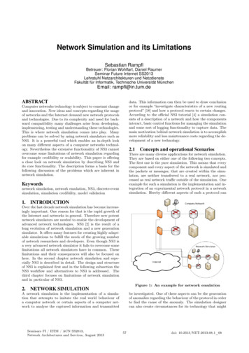
What is history matching?UpdateparametersProduction onlyHistory1.251.000.750.500.250.0001234time (year)Compareobserved & predicteddata0.8Production onlyHistory0.6Run simulationGOR Adjusting the simulator input insuch a way as to achieve abetter fit to the actual reservoirperformance. The changes in the simulationmodel should most closelyreflect the changes in theGenerateunderstanding of the fieldnewgeology.model The field and individual wellscumulative productions, watercuts and pressures are those formatchingNormalised water production rate1.500.40.2Heriot Watt University, Reservoir simulation course0.0012time (year)34
Prediction with uncertainty“If a man will begin withcertainties, he shall endin doubts, but if he willbe content to beginwith doubts, he shallend in certainties.“Francis Bacon
Uncertainty handlingPossible sources of error can be Inaccuracies in the size of the reservoir, areal extent, thickness, net togross. Lack of knowledge about reservoir architecture, sand bodies, faciesdistribution, shales, faults, etc. Uncertainties in the numerical values of rock properties (porosity andpermeability). Inaccuracy in the fluid properties like viscosity and FVF. Lack of sufficient data.
Reservoir simulation model “Is a grid block model of a petroleum reservoir where each of theblocks represents a local part of the reservoir. Within a grid blockthe properties are uniform although they might change with timeas the reservoir process progresses. Blocks are generallyconnected to neighbouring blocks so fluids flow in a block toblock manner. The model incorporates data on the reservoirfluids (PVT) and the reservoir description and their distribution inspace.”Heriot Watt University, Reservoir simulation course
Field applications Reservoir simulation may be applied at any stage at the early, middleor late field lifetime:Appraisal stage: reservoir simulation can be used to design the overallfield development plan, in terms of: The nature of recovery mechanism (natural depletion, waterflood, gasinjection) The nature of facilities required to develop the field (platform, subseadevelopment tieback, etc) The nature and capacities of plant, compression capacity, separationcapacities. The number, locations and type of wells. The sequence of wells drilling.Heriot Watt University, Reservoir simulation course
Field applications Reservoir simulation may be applied at any stage at the early, middle orlate field lifetime: Mature field development: it has been production for some time butthere is still a reasonably long life ahead for the field. At this stagereservoir simulation is a tool for reservoir management which allowsthe reservoir engineer to plan and evaluate different developmentoptions The engineer now has some production history, pressures,cumulative oil, water cuts and GOR’s. at this stage typical simulationactivities are:Heriot Watt University, Reservoir simulation course
Field applications Mature field development (cont ) History matching in order to obtain a better tuned reservoirmodel. Using the history match to re-visit the development plan (infilldrilling, injection capacities, etc). Review the reservoir recovery mechanism, better understating ofthe reservoir physics. Decide among smaller projects like “attic” drilling.Heriot Watt University, Reservoir simulation course
Field applications Late field development: defined as the closing few years of fieldproduction before abandonment. Is it worth to study the reservoirany further? Assess new options in the development plan thatcan give a “new lease of life” to the reservoir. i.e. new drillingtechnology, stimulation campaign, IOR implementation.Heriot Watt University, Reservoir simulation course
Thank you52
2.1 Reservoir, wells and plant technical limits "Understand the recovery technical limit and current predicted recovery, and then evaluate and select future recovery options (new wells, improved oil recovery, enhanced oil recovery, etc) to maximise economic recovery"