Transcription
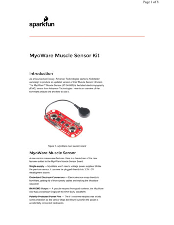
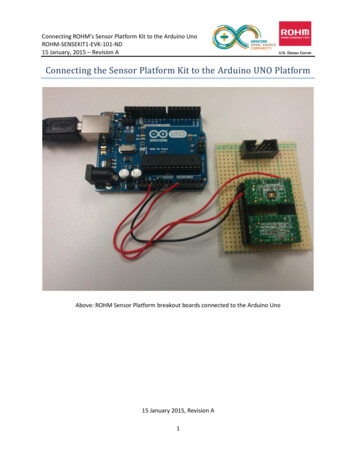
Connecting ROHM’s Sensor Platform Kit to the Arduino UnoROHM-SENSEKIT1-EVK-101-ND15 January, 2015 – Revision AConnecting the Sensor Platform Kit to the Arduino UNO PlatformAbove: ROHM Sensor Platform breakout boards connected to the Arduino Uno15 January 2015, Revision A1
Connecting ROHM’s Sensor Platform Kit to the Arduino UnoROHM-SENSEKIT1-EVK-101-ND15 January, 2015 – Revision ATable of ContentsCopyright and License . 3Revision History . 3Introduction . 4Getting Started. 4Connecting ROHM Breakout Boards to the Arduino UNO . 5General Information . 5Hardware Connection for ROHM BH1721 Digital ALS to the Arduino Uno . 6Software Explanation for ROHM BH1721 Digital ALS to the Arduino Uno . 6Hardware Connection for ROHM BH1620 Analog ALS to the Arduino Uno . 7Software Explanation for ROHM BH1620 Analog ALS to the Arduino Uno . 7Hardware Connection for ROHM BU52011 Hall Sensor to the Arduino Uno . 8Software Explanation for ROHM BU52011 Hall Sensor to the Arduino Uno . 9Hardware Connection for ROHM BDE0600G Temp Sensor to the Arduino Uno. 9Software Explanation for ROHM BDE0600G Temp Sensor to the Arduino Uno . 10Hardware Connection for LAPIS ML8511 UV Sensor to the Arduino Uno . 11Software Explanation for LAPIS ML8511 UV Sensor to the Arduino Uno . 11Hardware Connection for Kionix KMX061 Accel Mag Sensor to the Arduino Uno . 12Software Explanation for Kionix KMX061 Accel Mag Sensor to the Arduino Uno . 132
Connecting ROHM’s Sensor Platform Kit to the Arduino UnoROHM-SENSEKIT1-EVK-101-ND15 January, 2015 – Revision ACopyright and LicenseThe following except is copied directly from the Arduino FAQ (http://arduino.cc/en/Main/FAQ)“What do you mean by open-source hardware?” - Open-source hardware shares much of the principlesand approach of free and open-source software. In particular, we believe that people should be able tostudy our hardware to understand how it works, make changes to it, and share those changes. Tofacilitate this, we release all of the original design files (Eagle CAD) for the Arduino hardware. These filesare licensed under a Creative Commons Attribution Share-Alike license, which allows for both personaland commercial derivative works, as long as they credit Arduino and release their designs under thesame license.The Arduino software is also open-source. The source code for the Java environment is released underthe GPL and the C/C microcontroller libraries are under the LGPL.Please note that all references to ROHM’s Sensor Platform Kit are also shared under open sourceguidelines under the GNU General Public License, Version 3. Details can be found at the following mEVK.Revision HistoryDate12 January 2015DescriptionFirst DraftRevision IDA3
Connecting ROHM’s Sensor Platform Kit to the Arduino UnoROHM-SENSEKIT1-EVK-101-ND15 January, 2015 – Revision AIntroductionThe following document was written to provide a brief connection guide and starting point for usingROHM’s Sensor Platform Kit with the Arduino Uno. This guide assumes that the user has basicfunctional knowledge of both the Sensor Platform Kit and the Arduino itself. If this is not correct, pleasesee the following links for other guides and information on these products.ROHM’s Sensor Platform Kit: rduino: http://arduino.cc/Please note that the Arduino platform is a microcontroller platform; thus, this document will explain andshow examples of how to connect to and convert values for the ROHM Sensor Kit Sensors. This includesthe following: ROHM BH1721 – Digital Ambient Light SensorROHM BH1620 – Analog Ambient Light SensorROHM BU52011HFV – Hall Switch SensorROHM BDE0600G – Analog Temperature SensorLAPIS ML8511 – Analog UV SensorKionix KMX061 – Digital Accelerometer and MagnetometerGetting Started1. Initial Setupa. ROHM Sensor Platform Kiti. For this guide, we will be referring to the breakout boards included with theROHM Sensor Platform Kit. Thus, the base board will not be used in this setupb. The following are recommended for using the Arduino Uno for this guidei. PC with Arduino IDEii. USB Cable to power and monitor serial communicationiii. Download the example file “ROHM SensorKitBreakoutBoardConnect 1-132015.ino” from This document will refer to this code to help explain how to connect andproperly calculate sensor data.4
Connecting ROHM’s Sensor Platform Kit to the Arduino UnoROHM-SENSEKIT1-EVK-101-ND15 January, 2015 – Revision AConnecting ROHM Breakout Boards to the Arduino UNOGeneral Information ROHM’s Sensor Platform Breakout Boards have the same pinout across all the different sensors.If you are looking at the board from the top, the breakout board pinout will be as follows:oThe top row of pins is in place to “key” the sensor onto the base boards; however, they do nothave any use when connecting to different platforms. We recommend mounting the breakoutboard on standoffs to avoid connections to these pinsoPlease note that breakout board schematics can also be found at the following site:o https://github.com/ROHMUSDC/ROHMSensorPlatformEVK5
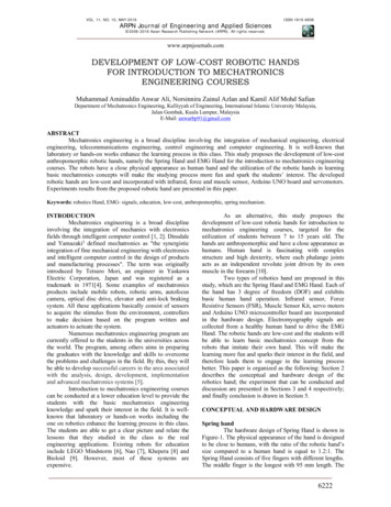
Connecting ROHM’s Sensor Platform Kit to the Arduino UnoROHM-SENSEKIT1-EVK-101-ND15 January, 2015 – Revision AHardware Connection for ROHM BH1721 Digital ALS to the Arduino Uno ROHM BH1721 – Digital Ambient Light Sensor Breakout Board SchematicoAs seen in the schematic above, this device connects 4 pins.o VDD – Connect directly to Arduino 3.3V output pin on power connectoro GND – Connect directly to Arduino GND pin on the power connectoro I2C Connection Note: User can specify the I2C pins, but in the example application, I2C isconnected as follows SDA – Pin A4 SCL – Pin A5 Note: There are no pull-up resistors on the breakout board or the Arduino Uno.Thus, please be sure to add pull-up resistance to both SDA and SCL pins.10kohm resistors were used when writing this example codeSoftware Explanation for ROHM BH1721 Digital ALS to the Arduino Uno Code Segments pertaining to this sensor can be found by defining and seeing code within the“DigitalALS” #ifDef statementsPseudo-Code Explanation1. Define Relevant Variables2. Begin setup()1. Initialize the I2C output Note: this sensor uses the “wire” library built into Arduino to read andwrite send the I2C commands (http://arduino.cc/en/reference/wire)2. Configure the Digital ALS once Send the Power ON Byte (0x01) to ALS device address (0x23)6
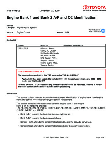
Connecting ROHM’s Sensor Platform Kit to the Arduino UnoROHM-SENSEKIT1-EVK-101-ND15 January, 2015 – Revision A Send Continuous Auto-Resolution Mode Setting (0x10) to ALS deviceaddress (0x23)3. Begin loop()1. Read 2 Bytes from Sensor, [0][1]2. Format the two bytes into an INT Sensor Out [0] 8 [1]3. Convert to Lux Sensor Out / 1.24. Format Serial Output and Return informationHardware Connection for ROHM BH1620 Analog ALS to the Arduino Uno ROHM BH1620 – Analog Ambient Light Sensor Breakout Board SchematicoAs seen in the schematic above, this device connects 5 pins.o VDD – Connect directly to Arduino 3.3V output pin on power connectoro GND – Connect directly to Arduino GND pin on the power connectoro ADC0 – ADC Output for Temperature Readings Note: User can specify which ADC pin, but in the example application, this partis connected as follows ADC0 – Pin A0o GPIO0, GPIO1 These pins are used to program the different mode gain options. These pins arenot used in the example application.Software Explanation for ROHM BH1620 Analog ALS to the Arduino Uno Code Segments pertaining to this sensor can be found by defining and seeing code within the“AnalogALS” #ifDef statementsPseudo-Code Explanation1. Define Relevant Variables2. Begin loop()1. Read back the Analog Sensor Output from Pin A07
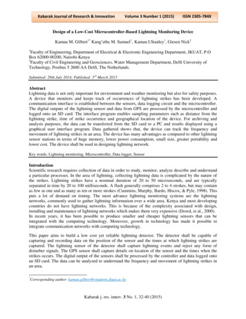
Connecting ROHM’s Sensor Platform Kit to the Arduino UnoROHM-SENSEKIT1-EVK-101-ND15 January, 2015 – Revision A Note: Default Arduino Reference voltage is 5V; however we aresupplying 3.3V to the sensor. Take these values into account whenperforming your conversions!2. Convert Analog Sensor Output to V, then to Lx Convert to Vo ADC Voltage (sensorValue / 670) * 3.3Vo ADC Voltage sensorValue * (3.3V/670)o ADC Voltage sensorValue * 0.004925 Convert to Evo Ev ADC Voltage/((0.57x10 -6)*R1), R1 5600o Ev ADC Voltage*(1/(0.57x10 -6*5600))o Ev ADC Voltage * 313.28o Ev sensorValue * 0.004925 * 313.28o Ev sensorValue * 1.5433. Format Serial Output and Return informationHardware Connection for ROHM BU52011 Hall Sensor to the Arduino Uno ROHM BU52011HFV – Hall Switch SensoroAs seen in the schematic above, this device connects 4 pins.o VDD – Connect directly to Arduino 3.3V output pin on power connectoro GND – Connect directly to Arduino GND pin on the power connector8
Connecting ROHM’s Sensor Platform Kit to the Arduino UnoROHM-SENSEKIT1-EVK-101-ND15 January, 2015 – Revision AoGPIO0, GPIO1 – Indicate Hall Switch Output Note: User can specify which digital input pins are used, but in the exampleapplication, this part is connected as follows GPIO0 – pin 7 (on the Arduino digital header) GPIO1 – pin 8 (on the Arduino digital header)Software Explanation for ROHM BU52011 Hall Sensor to the Arduino Uno Code Segments pertaining to this sensor can be found by defining and seeing code within the“HallSen” #ifDef statementsPseudo-Code Explanation1. Define Relevant Variables2. Begin setup()1. Setup Arduino Pins 7 and 8 and Input pins3. Begin loop()1. Perform digital reads on pins 7 and 8 Output will be either 1 or 0 and will indicate presence of north or southmagnetic fields2. Format Serial Output and Return InformationHardware Connection for ROHM BDE0600G Temp Sensor to the Arduino Uno ROHM BDE0600G – Analog Temperature SensoroAs seen in the schematic above, this device connects 4 pins.o VDD – Connect directly to Arduino 3.3V output pin on power connectoro GND – Connect directly to Arduino GND pin on the power connectoro ADC0 – ADC Output for Temperature Readings9
Connecting ROHM’s Sensor Platform Kit to the Arduino UnoROHM-SENSEKIT1-EVK-101-ND15 January, 2015 – Revision A oNote: User can specify which ADC pin, but in the example application, this partis connected as follows ADC0 – Pin A1GPIO0 This pin is used to trigger the thermostat output function. This pin is not used inthe example application.Software Explanation for ROHM BDE0600G Temp Sensor to the Arduino Uno Code Segments pertaining to this sensor can be found by defining and seeing code within the“AnalogTemp” #ifDef statementsPseudo-Code Explanation1. Define Relevant Variables2. Begin Loop()1. Read back the Analog Sensor Output from Pin A1 Note: Default Arduino Reference voltage is 5V; however we aresupplying 3.3V to the sensor. Take these values into account whenperforming your conversions!2. Convert value to V, then to Temperature reading Known Valueso Temperature Sensitivity -10.68mV/degCo Temperature Sensitivity -0.01068V/degCo Temp Known Point 1.753V @ 30 degC Calculationo ADC Voltage (sensorValue / 670) * 3.3Vo ADC Voltage sensorValue * (3.3V/670)o ADC Voltage sensorValue * 0.004925o Temperature (in deg C) (ADC Voltage - 1.753)/(-0.01068) 303. Format Serial Output and Return Information10
Connecting ROHM’s Sensor Platform Kit to the Arduino UnoROHM-SENSEKIT1-EVK-101-ND15 January, 2015 – Revision AHardware Connection for LAPIS ML8511 UV Sensor to the Arduino Uno LAPIS ML8511 – Analog UV SensoroAs seen in the schematic above, this device connects 3 pins.o VDD – Connect directly to Arduino 3.3V output pin on power connectoro GND – Connect directly to Arduino GND pin on the power connectoro ADC0 – ADC Output for UV Sensor Output Note: User can specify which ADC pin, but in the example application, this partis connected as follows ADC0 – Pin A2o GPIO0 This pin is used to trigger standby mode for the UV sensor. This pin is not usedin the example application.Software Explanation for LAPIS ML8511 UV Sensor to the Arduino Uno Code Segments pertaining to this sensor can be found by defining and seeing code within the“AnalogUV” #ifDef statementsPseudo-Code Explanation1. Define Relevant Variables2. Begin Loop()1. Read back the Analog Sensor Output from Pin A2 Note: Default Arduino Reference voltage is 5V; however we aresupplying 3.3V to the sensor. Take these values into account whenperforming your conversions!2. Convert value to V, then to UV Intensity Known Values11
Connecting ROHM’s Sensor Platform Kit to the Arduino UnoROHM-SENSEKIT1-EVK-101-ND15 January, 2015 – Revision Ao UV Sensitivity 0.129 V/(mW/cm2)o Temp Known Point 2.2V @ 10mW/cm2 Calculationo ADC Voltage (sensorValue / 670) * 3.3Vo ADC Voltage sensorValue * (3.3V/670)o ADC Voltage sensorValue * 0.004925o UV Intensity (in mW/cm2) (ADC Voltage - 2.2)/(0.129) 103. Format Serial Output and Return InformationHardware Connection for Kionix KMX061 Accel Mag Sensor to the ArduinoUno Kionix KMX061 – Digital Accelerometer and MagnetometeroAs seen in the schematic above, this device connects 6 pins.o VDD – Connect directly to Arduino 3.3V output pin on power connectoro GND – Connect directly to Arduino GND pin on the power connectoro I2C Connection Note: User can specify the I2C pins, but in the example application, I2C isconnected as follows SDA – Pin 4 (on Arduino Digital Header) SCL – Pin 5 (on Arduino Digital Header) Note: There are no pull-up resistors on the breakout board or the Arduino Uno.Thus, please be sure to add pull-up resistance to both SDA and SCL pins.10kohm resistors were used when writing this example codeo GPIO0/GPIO112
Connecting ROHM’s Sensor Platform Kit to the Arduino UnoROHM-SENSEKIT1-EVK-101-ND15 January, 2015 – Revision A This pin is used monitor the interrupt pins on the KMX61. These pins are notused in the example application.Software Explanation for Kionix KMX061 Accel Mag Sensor to the ArduinoUno Code Segments pertaining to this sensor can be found by defining and seeing code within the“DigitalMEMs” #ifDef statementsPseudo-Code Explanation1. Define Relevant Variables2. Begin setup()1. Initialize the I2C output Note: this sensor uses the “SoftI2CMaster” library to read and writesend the I2C commands (http://arduino.cc/en/reference/wire). Thiswas required because the “wire” library does not support the “repeatedstart” condition which is required for I2C reads from the KMX061 This Library is not built into the Arduino IDE. Resources for this can befound at the following address:o ryo https://github.com/felias-fogg/SoftI2CMaster2. Configure the Accel/Mag Sensor once by performing the following reads 1. Standby Register (0x29), write 0x03 (Turn Off) 2. Self Test Register (0x60), write 0x00 3. Control Register 1 (0x2A), write 0x13 4. Control Register 2 (0x2B), write 0x00 5. ODCNTL Register (0x2C), write 0x00 6. Temp EN Register (0x4C), write 0x01 7. Buffer CTRL Register 1 (0x78), write 0x00 8. Buffer CTRL Register 2 (0x79), write 0x00 9. Standby Register (0x29), write 0x0u Note: Please see the KMX061 Datasheet for additional information onthese registers3. Begin loop()1. Read back the Accelerometer output by reading 6 Bytes starting from address0x0A. [0][1].[5]2. Format Each of the X, Y, and Z axis acceleration Xout ([1] 6) ([0] 2) Yout ([3] 6) ([2] 2) Zout ([5] 6) ([4] 2)13
Connecting ROHM’s Sensor Platform Kit to the Arduino UnoROHM-SENSEKIT1-EVK-101-ND15 January, 2015 – Revision A 3.4.5.6.7.Note: to save some time with conversions, please note that theseoutputs are meant to be unsigned 14bit values. Thus, to make it easierto convert we recommend the following o Xout (float)(([1] 8) ([0]))/4o Yout (float)(([3] 8) ([2]))/4o Zout (float)(([5] 8) ([4]]))/4Convert Returned Value to G Axis ValueInG MEMS Accel axis / 1024Read back the Mag Sensor output by reading 6 Bytes starting from address0x12. [0][1].[5]Format Each of the X, Y, and Z axis mag data Xout ([1] 6) ([0] 2) Yout ([3] 6) ([2] 2) Zout ([5] 6) ([4] 2) Note: to save some time with conversions, please note that theseoutputs are meant to be unsigned 14bit values. Thus, to make it easierto convert we recommend the following o Xout (float)(([1] 8) ([0]))/4o Yout (float)(([3] 8) ([2]))/4o Zout (float)(([5] 8) ([4]]))/4Convert Returned Value to uT Axis ValueInuT MEMS Mag axis / 0.146Format Serial Output and Return Information14
//Appendix A: Arduino ------------------ROHM Sensor Platform Breakout Board Sensor Return ApplicationThis program reads the value of the connected ROHM Sensors andreturns the sensor output using the serial portCreated 13 January 2015by ROHM USDC Applications Engineering ------------------// ----- Debugging Definitions ----#define AnalogALS#define AnalogTemp#define AnalogUV#define HallSen#define DigitalALS#define DigitalMEMs// ----- Included Files ----#include Wire.h //Default I2C #defineSCL PIN4//Note that if you are using the Accel/MaSCL PORTPORTD//install the "SoftI2CMaster" as "Wire" dSDA PIN5//References:SDA PORTPORTD// http://playground.arduino.cc/Main/So SoftI2CMaster.h // https://github.com/felias-fogg/SofI2C TIMEOUT 1000// Sets Clock Stretching up to 1secI2C FASTMODE1// Sets 400kHz operating speed// ----- Globals ----//ADC Globals - Analog ALS, Temp, UVint ADCpin AnalogALS A0;int ADCpin AnalogTemp A1;int ADCpin AnalogUV A2;int sensorValue 0;
float sensorConvert 0;//Digital Input Globals - Hall Sensorint Hall Out0 0;int Hall Out1 0;//I2C globals (using wire library) - Digital ALSint DigitalALS DeviceAddress 0x23;unsigned char ALS highByte 0;unsigned char ALS lowByte 0;unsigned int ALSReturn 0;//I2C globals (using SoftI2CMaster libary) - MEMs Kionix Sensorint I2C check 0;int DigitalMEMS DeviceAddress 0x1C;//this is the 8bit address,//Accel Portionint MEMS Accel Xout highByte 0;int MEMS Accel Xout lowByte 0;int MEMS Accel Yout highByte 0;int MEMS Accel Yout lowByte 0;int MEMS Accel Zout highByte 0;int MEMS Accel Zout lowByte 0;int MEMS Accel Xout 0;int MEMS Accel Yout 0;int MEMS Accel Zout 0;float MEMS Accel Conv Xout 0;float MEMS Accel Conv Yout 0;float MEMS Accel Conv Zout 0;//Mag Sensor Portionint MEMS Mag Xout highByte 0;int MEMS Mag Xout lowByte 0;int MEMS Mag Yout highByte 0;int MEMS Mag Yout lowByte 0;int MEMS Mag Zout highByte 0;int MEMS Mag Zout lowByte 0;int MEMS Mag Xout 0;
int MEMS Mag Yout 0;int MEMS Mag Zout 0;float MEMS Mag Conv Xout 0;float MEMS Mag Conv Yout 0;float MEMS Mag Conv Zout 0;void setup(){Wire.begin();// start I2C functionalitySerial.begin(9600); // start serial port at 9600 bpswhile (!Serial) {;// wait for serial port to connect. Needed for Leonardo only}pinMode(13, OUTPUT);//Setup for the LED on BoardpinMode(7, INPUT PULLUP);pinMode(8, INPUT PULLUP);//----- Start Initialization for BH1721 Digital ALS ----// 1. Send 1 Power On Byte (0x01u)// 2. Send 1 Continuous Auto-Resolution Mode Byte (0x10u or 0x20u)#ifdef DigitalALSWire.beginTransmission(DigitalALS ion();delay(100);Wire.beginTransmission(DigitalALS ion();delay(100);#endif//----- END Initialization for BH1721 Digital ALS ----//----- Start Initialization for KMX061 Digital Accel/Mag Sensor #ifdef DigitalMEMs// 1. Standby Register (0x29), write 0x03 (Turn Off)// 2. Self Test Register (0x60), write 0x00
//////////////3.4.5.6.7.8.9.Control Register 1 (0x2A), write 0x13Control Register 2 (0x2B), write 0x00ODCNTL Register (0x2C), write 0x00Temp EN Register (0x4C), write 0x01Buffer CTRL Register 1 (0x78), write 0x00Buffer CTRL Register 2 (0x79), write 0x00Standby Register (0x29), write 0x0uI2C check i2c init();if(I2C check false){while(1){Serial.write("I2C Init Failed (SDA or SCL may not be pulledSerial.write(0x0A); //Print Line FeedSerial.write(0x0D); //Print Carrage Returndelay(500);}}i2c start(DigitalMEMS DeviceAddress);//This needs the 8 bit addi2c write(0x29);i2c write(0x03);i2c stop();i2c start(DigitalMEMS DeviceAddress);//This needs the 8 bit addi2c write(0x60);i2c write(0x00);i2c stop();i2c start(DigitalMEMS DeviceAddress);//This needs the 8 bit addi2c write(0x2A);i2c write(0x13);i2c stop();i2c start(DigitalMEMS DeviceAddress);//This needs the 8 bit addi2c write(0x2B);i2c write(0x00);i2c stop();
i2c start(DigitalMEMS DeviceAddress);//This needs the 8 bit addi2c write(0x2C);i2c write(0x00);i2c stop();i2c start(DigitalMEMS DeviceAddress);//This needs the 8 bit addi2c write(0x4C);i2c write(0x01);i2c stop();i2c start(DigitalMEMS DeviceAddress);//This needs the 8 bit addi2c write(0x78);i2c write(0x00);i2c stop();i2c start(DigitalMEMS DeviceAddress);//This needs the 8 bit addi2c write(0x79);i2c write(0x00);i2c stop();i2c start(DigitalMEMS DeviceAddress);//This needs the 8 bit addi2c write(0x29);i2c write(0x00);i2c stop();#endif//----- END Initialization for KMX061 Digital Accel/Mag Sensor --}void loop(){digitalWrite(13, HIGH);delay(250);digitalWrite(13, LOW);delay(250);// turn the LED on (HIGH is the voltage// wait for a second// turn the LED off by making the volta// wait for a second//---------- Start Code for Reading BH1620FVC Analog Ambient Ligh
#ifdef AnalogALS//----- Start ADC Read from Port A0 ---//Notes on Arduino ADC//Arduino uses an 5V ADC Reference Voltage; thus, we will need to//to 3.3V Levels to safely operate the sensors//5V 1024, 3.3V 670sensorValue analogRead(ADCpin AnalogALS);Serial.write("ADC Raw Value Return ");Serial.print(sensorValue);Serial.write(0x0A); //Print Line FeedSerial.write(0x0D); //Print Carrage Return//Calculations for Analog ALS - BH1620FVC// Note: Device's default configuration is in "High Gain Mode"// Note: Default R1 is 5.6kohm// Math: ADC Voltage (sensorValue / 670) * 3.3V//ADC Voltage sensorValue * (3.3V/670)//ADC Voltage sensorValue * 0.004925//Ev ADC Voltage/((0.57x10 -6)*R1), R1 5600//Ev ADC Voltage*(1/(0.57x10 -6*5600))//Ev ADC Voltage * 313.28//Ev sensorValue * 0.004925 * 313.28//Ev sensorValue * 1.543////sensorConvert (float)sensorValue*1.543;Serial.write("Analog ALS Converted Return ");Serial.print(sensorConvert);Serial.write(" lx");Serial.write(0x0A); //Print Line FeedSerial.write(0x0D); //Print Carrage Return#endif//---------- End Code for Reading BH1620FVC Analog Ambient Light S//---------- Start Code for Reading BDE0600G Analog Temperature Se#ifdef AnalogTemp
//----- Start ADC Read from Port A1 ---//Notes on Arduino ADC//Arduino uses an 5V ADC Reference Voltage; thus, we will need to//to 3.3V Levels to safely operate the sensors//5V 1024, 3.3V 670sensorValue analogRead(ADCpin AnalogTemp);Serial.write("ADC Raw Value Return ");Serial.print(sensorValue);Serial.write(0x0A); //Print Line FeedSerial.write(0x0D); //Print Carrage Return//Calculations for Analog Temp Sensor - BDE0600G// Temperature Sensitivity -10.68mV/degC// Temperature Sensitivity -0.01068V/degC// Temperature Sensitivity -93.63degC/V// Temp Known Point 1.753V @ 30DegC// Math: ADC Voltage (sensorValue / 670) * 3.3V//ADC Voltage sensorValue * (3.3V/670)//ADC Voltage sensorValue * 0.004925//Temperature (ADC Voltage - 1.753)/(-0.01068) 30//sensorConvert (float)sensorValue * 0.004925;sensorConvert (sensorConvert - 1.753)/(-0.01068) 30;Serial.write("Analog Temp Sensor Converted Return ");Serial.print(sensorConvert);Serial.write(" degC");Serial.write(0x0A); //Print Line FeedSerial.write(0x0D); //Print Carrage Return#endif//---------- End Code for Reading BDE0600G Analog Temperature Sens//---------- Start Code for Reading ML8511 Analog UV Sensor ----#ifdef AnalogUV//----- Start ADC Read from Port A2 ---//Notes on Arduino ADC//Arduino uses an 5V ADC Reference Voltage; thus, we will need to
//to 3.3V Levels to safely operate the sensors//5V 1024, 3.3V 670sensorValue analogRead(ADCpin AnalogUV);Serial.write("ADC Raw Value Return ");Serial.print(sensorValue);Serial.write(0x0A); //Print Line FeedSerial.write(0x0D); //Print Carrage Return//Calculations for UV Sensor - ML8511//Known Point 2.2V @ 10mW/cm2//Rate 0.129// Math: ADC Voltage (sensorValue//ADC Voltage sensorValue *//ADC Voltage sensorValue *//UV Intensity (ADC Voltage/ 670) * 3.3V(3.3V/670)0.004925- 2.2)/(0.129) 10////ConvsensorConvert (float)sensorValue * 0.004925;sensorConvert (sensorConvert - 2.2)/(0.129) 10;Serial.write("Analog UV Sensor Converted Return ");Serial.print(sensorConvert);Serial.write(" mW/cm2");Serial.write(0x0A); //Print Line FeedSerial.write(0x0D); //Print Carrage Return#endif//---------- End Code for Reading ML8511 Analog UV Sensor ------//---------- Start Code for Reading BU52011HFV Hall Sensor -----#ifdef HallSen//Hardware Connection//For the Hall Sensor, we only need to monitor digital inputs for//Connect Pin1 of Hall Sensor Header U111 to Arduino Pin7//Connect Pin2 of Hall Sensor Header U111 to Arduino Pin8Hall Out0 digitalRead(7);Hall Out1 digitalRead(8);Serial.write("HallOut0 ");Serial.print(Hall Out0);Serial.write(0x0A); //Print Line Feed
Serial.write(0x0D); //Print Carrage ReturnSerial.write("HallOut1 ");Serial.print(Hall Out1);Serial.write(0x0A); //Print Line FeedSerial.write(0x0D); //Print Carrage Return#endif//---------- End Code for Reading BU52011HFV Hall Sensor -------//---------- Start Code for Reading BH1721 Digital Ambient Light#ifdef DigitalALS// -- Notes on Arduino I2C Connection -//I2C is built in using using the "wire" library//Uno, EthernetA4 (SDA), A5 (SCL) [UNO - THIS is the platf//Mega256020 (SDA), 21 (SCL)//Leonardo2 (SDA), 3 (SCL)//Due20 (SDA), 21 (SCL), SDA1, SCL1// -- Notes on ROHM BH1721 Digital ALS -//Device Address 0x23u//Intialization Routines (See Setup Function Above)// 1. Send 1 Power On Byte (0x01u)// 2. Send 1 Continuous Auto-Resolution Mode Byte (0x10u or 0x20u//Main Loop Routines// 1. Read 2 Bytes from Sensor, [0][1]// 2. Sensor Out [0] 8 [1]// 3. Convert to Lux Sensor Out / 1.2Wire.requestFrom(DigitalALS DeviceAddress, 2);ALS highByte Wire.read(); // First Byte Read back is the highALS lowByte Wire.read();// Second Byte Read back is the lowALSReturn ALS highByte 8 ALS lowByte;//Store char values iSerial.write("Digital ALS Raw ");Serial.print(ALSReturn);Serial.write(0x0A); //Print Line FeedSerial.write(0x0D); //Print Carrage ReturnALSReturn ALSReturn / 1.2;//Convert to Lx
Serial.write("Digital ALS Converted Value ");Serial.print(ALSReturn); // print the characterSerial.write(" Lx");Serial.write(0x0A); //Print Line FeedSerial.write(0x0D); //Print Carrage Return#endif//---------- End Code for Reading BH1721 Digital Ambient Light S//---------- Start Code for Reading KMX61 Kionix Accelerometer M#ifdef DigitalMEMs// -- Notes on Arduino I2C Connection -//I2C is built in using using the "wire" library//Uno, EthernetA4 (SDA), A5 (SCL) [UNO - THIS is the platf//Mega256020 (SDA), 21 (SCL)//Leonardo2 (SDA), 3 (SCL)//Due20 (SDA), 21 (SCL), SDA1, SCL1// -- Notes on ROHM KMX61 Accel/Mag Sensor -//Device Address 0x0Eu//12 Bit Return Value//Intialization Routines (See Setup function above)// 1. Standby Register (0x29), write 0x03 (Turn Off)// 2. Self Test Register (0x60), write 0x00// 3. Control Register 1 (0x2A), write 0x13// 4. Control Register 2 (0x2B), write 0x00// 5. ODCNTL Register (0x2C), write 0x00// 6. Temp EN Register (0x4C), write 0x01// 7. Buffer CTRL Register 1 (0x78), write 0x00// 8. Buffer CTRL Register 2 (0x79), write 0x00// 9. Standby Register (0x29), write 0x0u//Main Loop Routines// 1. Read 6 Bytes starting from address 0x0A. These will be the// 2. Xout ([1] 6) ([0] 2)// 3. Yout ([3] 6) ([2] 2)// 4. Zout ([5] 6) ([4] 2)// 5. Read 6 Bytes starting from addres 0x12. These will be the
// 6. Xout ([1] 6) ([0] 2)// 7. Yout ([3] 6) ([2] 2)// 8. Zout ([5] 6) ([4] 2)// Start Getting Data from Acceli2c start(DigitalMEMS DeviceAddress);i2c write(0x0A);i2c rep start(DigitalMEMS DeviceAddress 1);// Or-ed with "1"MEMS Accel Xout lowByte i2c read(false);MEMS Accel Xout highByte i2c read(false);MEMS Accel Yout lowByte i2c read(false);MEMS Accel Yout highByte i2c read(false);MEMS Accel Zout lowByte i2c read(false);MEMS Accel Zout highByte i2c read(true);i2c stop();//Note: The highbyte and low byte return a 14bit value, dropping//However, because we need the signed value, we will adjustMEMS Accel Xout (MEMS Accel Xout highByte 8) (MEMS Accel XoutMEMS Accel Yout (MEMS A
onnecting ROHM’s Sensor Platform Kit to the Arduino Uno ROHM-SENSEKIT1-EVK-101-ND 15 January, 2015 – Revision A 11 Hardware Connection for LAPIS ML8511 UV Sensor to the Arduino Uno LAPIS ML8511 – Analog UV Sensor o As seen in the schematic above, this device connects 3 pins. o VDD – Connect directly