Transcription
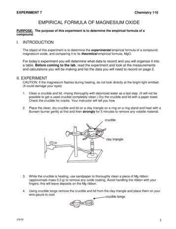
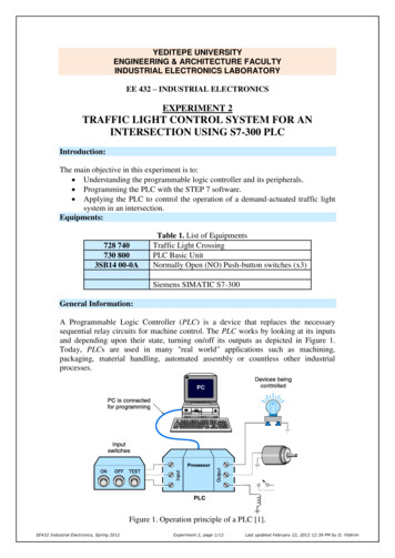
YEDITEPE UNIVERSITYENGINEERING & ARCHITECTURE FACULTYINDUSTRIAL ELECTRONICS LABORATORYEE 432 – INDUSTRIAL ELECTRONICSEXPERIMENT 2TRAFFIC LIGHT CONTROL SYSTEM FOR ANINTERSECTION USING S7-300 PLCIntroduction:The main objective in this experiment is to: Understanding the programmable logic controller and its peripherals. Programming the PLC with the STEP 7 software. Applying the PLC to control the operation of a demand-actuated traffic lightsystem in an intersection.Equipments:728 740730 8003SB14 00-0ATable 1. List of EquipmentsTraffic Light CrossingPLC Basic UnitNormally Open (NO) Push-button switches (x3)Siemens SIMATIC S7-300General Information:A Programmable Logic Controller (PLC) is a device that replaces the necessarysequential relay circuits for machine control. The PLC works by looking at its inputsand depending upon their state, turning on/off its outputs as depicted in Figure 1.Today, PLCs are used in many "real world" applications such as machining,packaging, material handling, automated assembly or countless other industrialprocesses.Figure 1. Operation principle of a PLC [1].EE432 Industrial Electronics, Spring 2012Experiment 2, page 1/12Last updated February 22, 2012 12:39 PM by D. Yildirim
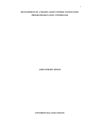
SIMATIC S7-300 PLC will be used to control the operation of a demand-actuatedtraffic light system in an intersection. The general features of S7-300 are; it has amodular PLC system developed for medium performance projects, it features differentmodules for different automation problems, it is easy to re-program the device whenan improvement is needed for the process, it is possible to be connected tocommunication networks such as MPI, Profibus and Industrial Ethernet, it has a vastamount of command set for programming.The S7-300 mounted on a rack is shown in Figure 2. It includes the followingcomponents: Power Supply (PS): It is required to supply the modules connected to thePLC. There are three different models for 2 A, 5 A, and 10 A max.CPU: The central processing unit.Interface Module (SM):1.2.3.4. Digital Input Modules: 24 V DC transistor,Digital Output Modules: 24 V DC transistor,Analog Input Module: Voltage, Current, Resistor and Thermocouple,Analog Output Module: Voltage and Current.Communication Module (CP)Figure 2. Main parts of a S7-300 PLCProgramming with STEP 7:STEP 7 software is used to program the PLC. There are three different programminglanguages in the STEP 7: statement list (STL) for users who prefer programming in aEE432 Industrial Electronics, Spring 2012Experiment 2, page 2/12Last updated February 22, 2012 12:39 PM by D. Yildirim
language similar to machine code, Ladder logic (LAD) for users who are accustomedto working with circuit diagrams, and Function Block Diagram (FBD) for users whoare familiar with the logic boxes of Boolean algebra. The S7 provides a vast variety ofcomponents into its component library which in turn is useful for variable applicationsfrom conventional control applications to applications with counters, timers, flipflops, mathematical functions for industrial feed-back control processes such as PIDcontroller design.In STEP 7, we work with addresses (absolute addressing) such as I/O signals, bitmemory, counters, timers, data blocks, and function blocks. An address is theabbreviation for a particular memory area and memory location, so it is important tocorrectly assign the input/output (I/O) address areas in the hardware configuration andspecify them in the program (STEP 7). An absolute address comprises an addressidentifier I (input bit),IB (input byte-8 bits),IW (input word-16 bits),ID (input double word-32 bits),Q (output bit), QB (output byte),QW (output word),QD (output double),M (memory bit),MB (memory byte),MW (memory word),MD (memory double word),T (timer),C (counter)] anda memory location (for example, Q 4.0, I 1.1, M 2.0, FB 21).Figure 3 shows the structure of an address for the input interface of a PLC.Figure 3. Address structure of a PLC.Due to the hardware structure, every input and output is assigned a default absoluteaddress. On the other hand, the absolute address can be replaced by a freely selectable(symbolic) name (e.g. Q 4.2: Automatic mode). Symbols are assigned independent ofthe programming language, that is, LAD, FBD or STL.Programming ExampleThe circuit shown in Figure 4 is used to control the direction of rotation of a threephase induction motor. There are three buttons that control the operation: two startbuttons – one for clockwise (CW), one for counterclockwise (CCW) and a single stopbutton. Based on these inputs PLC controls the operation of two contactors byactivating or deactivating relay coils. The direction of rotation in an induction motorcan be reversed by exchanging any two wires of three-phases that are connected to theEE432 Industrial Electronics, Spring 2012Experiment 2, page 3/12Last updated February 22, 2012 12:39 PM by D. Yildirim
voltage source. Two contactors must not be on at the some time as this woulddefinitely short circuit the three-phase supply.Figure 4. Controlling the direction of rotation employing a PLC.The circuit shown in Figure 4 is used to control the direction of rotation of a threephase induction motor. There are three buttons that control the operation: two startbuttons and one stop button. When S1 is pushed momentarily motor rotates in CWdirection and pushing S2 will rotate the motor in CCW direction. Pushing S3 button atany time will stop the motor.Figure 5 shows the ladder diagram for the operation of motor given in Figure 4. I0.0,I0.1, and I0.2 are corresponding switches of S1, S2, and S3, respectively. Figure 5ashows the simplest ladder diagram where continuous pushing of switches is requiredto operate the motor. In order to allow momentary pushing of buttons, a lockingmechanism must be employed as depicted in Figure 5b. Since two contactors cannotbe on at the some time, a protection mechanism must be employed to overcome thissituation. The resulting ladder diagram is shown in Figure 5c where when onecontactor is on, it automatically disables the other input.Symbol names may also be assigned in the ladder diagram instead of usinginput/output addresses. Figure 5d shows the symbol table for assigning names to eachinput/output. Once names are assigned, ladder diagram is automatically updated asshown in Figure 5e.EE432 Industrial Electronics, Spring 2012Experiment 2, page 4/12Last updated February 22, 2012 12:39 PM by D. Yildirim
(a)(b)(c)(d)(e)Figure 5. Programming with LAD language for the circuit in Figure 4: (a) simplestladder diagram (b) diagram with locking pushbuttons (c) complete ladder diagram (d)assigning names to symbols using symbol table (e) diagram with symbol names.EE432 Industrial Electronics, Spring 2012Experiment 2, page 5/12Last updated February 22, 2012 12:39 PM by D. Yildirim
TIMER TYPESTimers have an area reserved for them in the memory of your CPU. This memory areareserves one 16-bit word for each timer address. The ladder logic instruction setsupports 256 timers. The timer value is written as:Timer format:S5T# aH bbM ccS ddMS––where a hours, bb minutes, cc seconds, and dd millisecondsThe time base is selected automatically, and the value is rounded tothe next lower number with that time base.For example: 500ms S5T#500MS,1min 10sec S5T#1M 10SThere are five different timer types in Simatic Ladder programming as depicted inFigure 6 where each timer starts with an input signal.Figure 6. Timer typesEE432 Industrial Electronics, Spring 2012Experiment 2, page 6/12Last updated February 22, 2012 12:39 PM by D. Yildirim
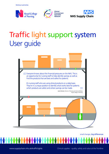
A sample use of a retentive on delay timer coil is illustrated in Figure 7 where timerT3 value is set to 5seconds. This timer starts when input I0.0 becomes high, i.e., ifI0.0 is a push-button switch, pressing this switch will turn on timer T3. This timer T3value will be high after 5 seconds.Figure 7. An example use for a retentive on-delay timer.TRAFFIC LIGHT CROSSINGFigure 8 shows the traffic light crossing simulator in this experiment where it employstwo inputs, named S0 and S1 (normally-open momentary type push-button switches),and six outputs (0 to 5). This board must be supplied with 24VDC voltage whereground must be connected to 0V and 24V must be connected to DC 24V terminals.When any input switch is pushed on, the input terminal that the switch is connectedbecomes 24VDC. Six output terminals control the operation of six Light EmittingDiodes (LEDs). When a particular output terminal is connected to 24VDC, the LEDwith that output number turns on.main roadauxiliary roadFigure 8. Traffic Light Crossing.EE432 Industrial Electronics, Spring 2012Experiment 2, page 7/12Last updated February 22, 2012 12:39 PM by D. Yildirim
PUSHBUTTON SWITCHPushbutton switches are momentary type normally open (NO) or normally closed(NC) type switches where some pressure must be maintained to keep the switchactivated. Some switches may employ both NO and NC type contacts as illustrated inFigure 9 where contacts numbered 1 and 2 are for NC and those marked 3 and 4 arefor NO terminals. These switches are used to send signals into the PLC as inputcommands. For example, a green pushbutton can be used to start a motor while a redone is used for stopping a motor.Figure 9. Pushbutton switch, normally-open and normally-closed type (seeAppendix A for data sheet)Procedure of Experiment:Circuit Set-up: Assemble the circuit shown in Figure 10. Please make sure that you follow the same input and output terminal numbersgiven in Figure 10 when you make connections (i.e., S1 must be connected to I0.1input terminal of PLC). Test the correctness of your connection by turning on output Q4.3 using thecorresponding switch on PLC. This will light up red LEDs on auxiliary road oftraffic light crossing 728 740. You can try to turn on other outputs as you desire.Open the STEP 7 software to program the PLC: Make an online connection between the PLC and the software by running thecommand from “File/Connect Online”. Make sure that the switch on PLC is set to RUN-P mode. Create a new project. Then, in “Program/OB1” (double click OB1) write yourcode in Ladder diagram (make sure to select “View/LAD”). Right Click on OB1 and choose “Download to CPU” command. Test your program for correct operation.EE432 Industrial Electronics, Spring 2012Experiment 2, page 8/12Last updated February 22, 2012 12:39 PM by D. Yildirim
Figure 10. PLC control of traffic lights in an intersection.Demand-actuated traffic light operation in an intersection:This simple demand-actuated traffic light control system consists of an intersectionwhere heavy traffic flows on main road and very light traffic is present on auxiliaryroad. Therefore, the lights on main road are always set to green whereas those onauxiliary road are set to red. When a car approaches on auxiliary road, sensors (eitherS0 or S1) detect that car, and traffic lights on main road turns from green-to-yellow andthen yellow-to-red after a predetermined time. Following red light on main road, thelights on auxiliary road turn from red-to-green (no yellow light). After a fixed timedelay, the lights on auxiliary road turn from green-to-red and those on main road turnfrom red-to-green. The timing sequence can be summarized as follows:1. Initially all traffic lights must be off.2. The traffic light system will start when either switch S2 (green button) or S4(yellow button) is momentarily pushed on.3. Pushing ON switch S2 will turn on green lights for main road and red lights forauxiliary road.4. Pushing FLASHING switch S4 will activate flashing operation where yellowlights on main road and red lights on auxiliary road are flashing at a rate of 1swith 0.5s on followed by 0.5s off. Please note that flashing light on each roadmust be flashing alternately – not at the same time, i.e., when yellow lights onmain street are on for 0.5s red lights on auxiliary street must be off and whenyellow lights turn off for 0.5s red lights must turn on for 0.5s. Flashingoperation is usually activated during very low traffic hours such as aftermidnight until dawn.5. At any time, pushing OFF switch S3 will turn off all lights.EE432 Industrial Electronics, Spring 2012Experiment 2, page 9/12Last updated February 22, 2012 12:39 PM by D. Yildirim
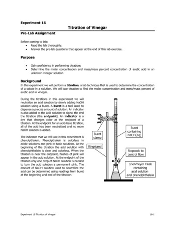
6. When traffic light system is operating with ON mode, i.e., green lights onmain road are on while red lights on auxiliary road are red, pushing either S0or S1 will initiate traffic light change after a 10s delay.7. After pressing either S0 or S1 the system will wait for 10s, then green lights onmain road will change to yellow lights (duration of yellow lights is 3s) and tored lights. At this instant there must be an overlap time where all lights are setto red for time duration of 2s (this is required for safety reasons).8. After this 2s overlap delay red lights on auxiliary road are turned to green (noyellow light).9. The yellow lights on auxiliary road will stay on for 15s to allow vehicles crossinto main road.10. After 15s, the green lights on auxiliary road will turn to red and those on mainroad will switch from red to green.11. Please note that under no circumstances, all green lights are turned on at thesame time as this definitely results in a vehicle collision.Conclusion:Figure 11 shows the construction of a device which fills 3 different bins withindividually prescribed mixture of balls having 3 different colors which are given inmixed form in a reservoir. A color sensor is used to recognize the color of the ball. Ifthere is a red ball in front of the sensor, then “ R “ output of the sensor becomes 1.“G” output becomes 1, if the ball is green and “B” becomes 1, when the ball is blue.Four valves are used to run the process properly. Directions and input signals of thevalves are shown in Figure 6.a) Describe the operation of the system.b) Write a PLC program in ladder diagram form to run this device properly: Determine the I/O addresses of the PLC which you use for this device.Determine the number of networks and function of each network.Logic gates, flip-flops, delay timers, counters, comparators, etc. can beused in your design.EE432 Industrial Electronics, Spring 2012Experiment 2, page 10/12Last updated February 22, 2012 12:39 PM by D. Yildirim
Figure 11. Ball sorting process.References:[1] A. Kilian, Modern Control Technology: Components and Systems, 2nd ed.,Delmar Thomson Learning, 2007.[2] T. E. Kissell, “Industrial Electronics: Applications for ProgrammableControllers, Instrumentation and Process Control and Electrical Machines andMotor Controls”, Prentice Hall, 3rd edition, 2002.[3] T. J. Maloney, Modern Industrial Electronics, 5th Ed., Prentice Hall, 2001.[4] T. Bartelt, Industrial Control Electronics, 3rd ed., Thomson Delmar Learning,2006.EE432 Industrial Electronics, Spring 2012Experiment 2, page 11/12Last updated February 22, 2012 12:39 PM by D. Yildirim
EXPERIMENT RESULT SHEETThis form must be filled in using a PEN. Use of PENCIL IS NOT ALLOWEDEXPERIMENT 4: TRAFFIC LIGHT CONTROL SYSTEM FOR ANINTERSECTION USING S7-300 PLCSTUDENT NOSTUDENT NAMESIGNATURE1234DATEINSTRUCTOR APPROVALPlease include flowchart of your program in here indicating inputs and outputs (ladderdiagram code must be included in your report).EE432 Industrial Electronics, Spring 2012Experiment 2, page 12/12Last updated February 22, 2012 12:39 PM by D. Yildirim
traffic light system in an intersection. The general features of S7-300 are; it has a modular PLC system developed for medium performance projects, it features different modules for different automation problems, it is easy to re-program the device when an improvement is