Transcription
HVL/cc Medium Voltage,Metal-Enclosed Switchgear2.4 to 38.0 kV, 60 to 150 kV BILClass 6045Catalog2004CONTENTSDescription . . . . . . . . . . . . . . . . . . . . . . . . . . . . . . . . . . . . . . . . . . . . . PageIntroduction. . . . . . . . . . . . . . . . . . . . . . . . . . . . . . . . . . . . . . . . . . . . . . . 3General and Application Information . . . . . . . . . . . . . . . . . . . . . . . . . . . 4Technical Overview . . . . . . . . . . . . . . . . . . . . . . . . . . . . . . . . . . . . . . . 12Selection Guide . . . . . . . . . . . . . . . . . . . . . . . . . . . . . . . . . . . . . . . . . . 15Typical Multiple Section Switchgear Arrangements . . . . . . . . . . . . . . . 21Standard Symbols . . . . . . . . . . . . . . . . . . . . . . . . . . . . . . . . . . . . . . . . 23Dimensions. . . . . . . . . . . . . . . . . . . . . . . . . . . . . . . . . . . . . . . . . . . . . . 24HVL/cc Grounding Switch Application . . . . . . . . . . . . . . . . . . . . . . . 26Optional Mechanism Features and Ratings . . . . . . . . . . . . . . . . . . . . . 33Typical Control Circuit . . . . . . . . . . . . . . . . . . . . . . . . . . . . . . . . . . . . . 34Optional Equipment . . . . . . . . . . . . . . . . . . . . . . . . . . . . . . . . . . . . . . . 35
HVL/cc Medium Voltage, Metal-Enclosed SwitchgearIntroductionIntroductionHVL/cc Medium Voltage, Metal-Enclosed Switchgear from Schneider Electric provides switching,metering, and interrupting capabilities for medium-voltage, electrical power distribution systems.It is designed to provide increased electrical and mechanical life. It improves reliability by reducing thenumber of bus connections and using new switch technology. HVL/cc is designed for easy systemexpansion and reduces equipment expense for systems ranging from 2.4 to 38.0 kV, 60 to 150 kV BIL.This switchgear is noted for its versatility, durability, and convenience. It can be used as serviceentrance equipment and for controlling substation transformers, and is designed and manufactured inaccordance with NEMA, CSA, UL, and ANSI/IEEE standards C37.20.3, C37.20.4, C37.57, C37.58,CSA 22.2 no. 31, and CSA 22.2 no. 193 where applicable.Made up of modular units, the HVL/cc is easy to expand. Two main bus positions allow futureextensions and connections to existing equipment.HVL/cc switchgear is available in either single or multiple section units. To simplify handling andinstallation, each section is assembled before shipping. The design is compact, with front accessibility.The HVL/cc switch can be equipped with either an over-toggle mechanism (OTM), which is standard,or an optional stored energy mechanism (SEM). An option with both mechanisms is the Fuselogic system. The Fuselogic system offers fuse tripping (with SEM) to provide protection against singlephasing loads when a fuse has blown. It also has a mechanical interlock to prevent inadvertentswitching until fuses have been installed or blown fuses have been replaced. (See additional details onpage 6). An optional blown fuse flag is available with either an OTM or an SEM. The Fuselogic systemon the OTM offers a Form “C” 1 N.O.-1 N.C. auxiliary contact in addition to the blown fuse flag.Mechanical interlocks are standard. This feature prevents the removal of the load-side panel while theload interrupter switch is closed and/or the optional ground switch is open.HVL/cc switchgear is available in both indoor and outdoor enclosures. Each has features to ensureconvenience, reliability, and durability.Indoor switchgear includes lifting angles at the top corners of each shipping section for ease inhandling, provisions for expansion, an 11-gauge steel enclosure, full-length ground bus in multiplesection enclosures, and padlocking provisions for the load-side panel. Optional features include keyinterlocking and clear windows for inspection of the optional Load-side Discharge Assembly (LDA).The outdoor switchgear is solidly constructed with a rear-sloping roof, a steel base and 11-gauge steelenclosure, gasketed front doors, and strip heaters in each switch section. Operating handles areenclosed by outer bulkhead type doors.The HVL/cc enclosure is designed for front access only and, with minimum clearance, can bepositioned against walls, in small rooms, or in prefabricated buildings. The small footprint can result inconsiderable cost savings from the reduction of building or room sizes.Meter sections are available in both hot and cold sequence designs for utilities and/or customerrequirements. (Please contact the factory for dimensions and availability.)Special utility metering sections can be provided as with our conventional HVL Metal-Enclosedswitchgear.07/20043 1999–2004 Schneider Electric All Rights Reserved
HVL/cc Medium Voltage, Metal-Enclosed SwitchgearGeneral and Application InformationGeneralSquare D-brand Medium Voltage, Metal-Enclosed Switchgear functions as a prime component ofmedium voltage, electrical power distribution systems providing necessary switching and overcurrentprotection for the medium-voltage feeders. It is often used in conjunction with Square D-brand unitsubstations. The switchgear is most frequently applied as service entrance equipment, although itperforms equally well in controlling substation transformers and in the sectioning of medium-voltagefeeder systems.Standard Features Tested per ANSI standards C37.20.3, C37.20.4, C37.57, C37.58, CSA 22.2 no. 31, and CSA 22.2no. 193 where applicable Over-toggle mechanism (OTM)Medium Voltage FuseStyle Required withHVL/cc Switchgear5.5 kV to 1080A15.5 kV to 480A17.5 kV to 270A Removable switch operating handles25.8 kV to 175A38.0 kV to 115A Visible isolation viewing ports to view open, closed, and grounded switch positionsFuse/cable access panel mechanically interlocked with the load interrupter switch and the optionalgrounding switchWith the optional grounding switch, the cable/fuse compartment is not accessible unless thegrounding switch is closed into the grounded positionStandard live line indicators (LLIs) powered by capacitor dividers internal to the insulators— On incoming circuits:Provide Incoming Live Line indicationProvide Incoming Line De-energized indication— On feeder circuits:Provide Live Load indicationProvide Load De-energized indicationProvide Blown Fuse indication (only on wye connected systems)Provide Back-fed Circuit indication Animated mimic bus— On ungrounded switches, indicates Closed and Open positions— On units with grounding switches, indicates Closed, Open, and Grounded positions Cable lugs (1 set per phase)— Up to two 500 kcmil cables per phase in switch bays— Up to four 500 kcmil cables per phase in incoming line terminal chambers (20-inch wide bay) 600/1200 A tin-plated copper main bus Provision for padlocks and/or key locks (optional).Belleville washers for all power connectionsBi-phenol epoxy switch enclosure and insulatorsUL/cULus labelsTested to IEC 420 for switch-fuse integration11-gauge steel enclosure.25 x 2 in. (6 x 51 mm) copper ground bus meeting ANSI requirements for short-circuit groundingDuplex switches. Single, load-side access panel mechanically interlocked to prevent access unlessboth switches are opened (key interlocks are not required)4 1999–2004 Schneider Electric All Rights Reserved07/2004
HVL/cc Medium Voltage, Metal-Enclosed SwitchgearGeneral and Application InformationOptions and Accessories Square D-brand “DIN-style” current-limiting fuses (with ANSI E-rated curves) manufactured byBussmann and stocked by Schneider Electric in Smyrna, TN and Bussmann in St. Louis, MO The Fuselogic system— Mechanical lockout feature to prevent reclosing the switch until three new fuses have beeninstalled— Single phasing protection due to blown fuses with the Fuselogic system— Blown fuse indicating contact for remote indication (one common contact)— Blown/missing fuse flag on mechanism cover Fault-making grounding switch— On incoming switches, grounds the incoming line— On feeder switches, grounds the outgoing load LDA for fused units only (used to discharge capacitive voltage in cables under blown fuseconditions; application A 17.5kV, 600 A only) Switch position auxiliary switch1200 A tin-plated copper main busLLIs on main busInfrared viewing windows for main bus and fuse/cable compartmentsDual-spring stored energy mechanism (SEM type)Motor operator for OTMs and SEMsOpening and closing coils (SEM only)Fast / Auto transfer configuration (Main-Main and Main-Tie-Main)— Electrically interlocked— Mechanically interlocked— Operated from LLIs Protective relaying—contact your local field sales representative for application assistanceDuplex configuration— optional mechanical interlock to lock out simultaneous closure of both duplex switches Surge arresters (Square D-brand standard polymer only)System Voltage 17.5 kVSystem Voltage 25.8 – 38.0 kVDistribution, Intermediate, and Station class 12 kVStandard 14.75 in. (375 mm) switch sectionOptional 20 in. (508 mm) and 29.50 in. (749 mm) sectionDistribution, Intermediate, and Station class 12 kVStandard 20 in. (508 mm) switch sectionOptional 29.50 in. (749 mm) Load-side surge arresters (all classes) with fuses require a39.37 in. (1000 mm) wide section. If unfused, a 29.5 in.(750 mm) wide section may be used.Modified cubicle widths for customers wanting additional working space for cable termination andfuse removal:System Voltage 17.5 kVSystem Voltage 25.8 – 38.0 kV20 in. (508 mm)39.37 in. (1000 mm)29.50 in. (750 mm) Low voltage compartment with hinged door— Space for Powerlogic metering or relaying system— Space for control components07/20045 1999–2004 Schneider Electric All Rights Reserved
HVL/cc Medium Voltage, Metal-Enclosed SwitchgearGeneral and Application Information Heaters with thermostat Stainless steel enclosures for corrosive environments. (Please consult the factory for availability.)Capacitor trip unitTransitions to other Square D-brand medium voltage equipment and power transformers. (Pleaseconsult the factory for details.)Class 1, Division 2 Hazardous Area Rated SwitchgearHVL/cc switchgear (up to 15 kV, 95 kV BIL, 600 A maximum) has been certified for use in Class 1,Division 2 hazardous locations. This classification usually includes locations where volatile flammableliquids, flammable gases, or vapors are used, but would become hazardous only in case of an accidentor some unusual operating condition.Modifications are made to the standard switchgear including:— Manual operation with no electrical controls, over-toggle mechanism (OTM) only— Optional, explosion proof, T3B rated heaters with sealed connections— Fuses without indicating pins— Modified LLI system that includes sealed connections at the insulator and plugged test ports toprevent use.These modifications are essential for the equipment to meet Class 1, Division 2 requirements. Thesemodifications cannot be altered. Do not substitute components.The Class 1, Division 2 switchgear without heaters are T5 rated and can be used in areas where theflash point of volatile liquids, gases, or vapors is 100 C/212 F or above. Class 1, Division 2switchgear with optional heaters are T3B rated and can be used in areas where the flash point ofvolatile liquids, gases, or vapors is 165 C/329 F or above.The Fuselogic SystemThe Square D-brand medium voltage current-limiting fuse sets the standard for features andprotection. The extended travel blown fuse indicator provides extended travel and increased energy topositively operate this optional feature.The Fuselogic system also prevents closing the HVL/cc switch if a fuse is blown or has not beeninstalled. This reduces the potential of equipment damage due to single phasing because of a blownor missing fuse. The Fuselogic system can be used to operate auxiliary contacts for optional localand/or remote indication or for fuse tripping.The Fuselogic fuse trip system requires the stored energy mechanism (SEM), with separate close andopen springs. The motor operator is optional on both OTMs and SEMs.Fuselogic System OptionsMechanism TypeAvailable OptionBlown fuse flagOver Toggle Mechanism (OTM)Stored Energy Mechanism (SEM)YYBlown fuse flag w/ remote indicationYYDirect acting fuse tripNYTime delay fuse trip via blown fuse–fuse sizedependent (control power required)NYNOTE: The Fuselogic system can only be operated by Square D-brand fuses.6 1999–2004 Schneider Electric All Rights Reserved07/2004
HVL/cc Medium Voltage, Metal-Enclosed SwitchgearGeneral and Application InformationShunt-Trip ApplicationsThe HVL/cc load interrupter switch is, by definition and standard, only required to interrupt itscontinuous current nameplate rating (for example, a 15 kV, 600 A rated HVL/cc can interrupt no morethan 600 A). Listed below are several applications in which it is appropriate to use a shunt trip coil, aswell as applications in which it should not be used.— Ground Fault Protection on Solidly Grounded Systems: Occasionally, to avoid the expenseof Visi/Vac circuit interrupter switchgear or Masterclad switchgear, specifications are writtento incorporate ground fault protection. Metal-enclosed switchgear is frequently used with solidlygrounded systems where available short-circuit current is 12.5 kA or more.The HVL/cc load interrupter switch cannot be considered or used for ground fault protection onsolidly grounded systems because the available fault current is far greater than its 600/1200 Aload interrupting rating.— Ground Fault Current on Resistively Grounded Systems: Frequently, three-phase electricalsystems have a grounding resistor. The grounding resistor limits the level of the ground faultcurrent and consequently reduces the potential damage to the equipment.If the system is resistively grounded with a nominally rated 400 A or less grounding resistor,then it may be possible to use HVL/cc metal-enclosed switchgear for ground fault protection.Please contact your local field sales representative to determine if this is an appropriateapplication.— Transformer Protection Applications: Medium voltage fuses are designed as short-circuitprotection devices and generally are able to provide adequate transformer overcurrentprotection per NEC 450.3.For applications where the fuse E rating is less than half of the rated interrupting current of theswitch, it may be possible to improve the overall protection scheme. Adding overcurrent(IEEE 51) relays can provide precise overload protection for the transformer.In this application, the selection of the CT ratio and the programming of the IEEE 51 overload(overcurrent) relay must be coordinated by the factory to ensure that the interrupting rating ofthe switch is not exceeded. Please contact your local field sales representative for applicationassistance.— Under/Over-Voltage Protection with Fuselogic System: The Fuselogic system is well suitedwhere under/over-voltage protection is required. The shunt trip coil, actuated by the voltagesensing relays, can be used to open the switch with the loss of incoming line voltage. Thisapplication requires optional voltage transformers (VTs) and voltage sensing relays.— Operating Times: OTM—The conventional single spring over-toggle mechanism equippedwith the motor operator operates in approximately five seconds. SEM—The stored energymechanism operates in approximately 100 milliseconds. The motor operator will recharge thesprings in approximately five seconds and prepare the switch for any reclose operations thatmay be required.Type of Equipment Available—Indoor and OutdoorSingle Section Switchgear contains a single fused or unfused switch in a free-standing enclosure. Itis ideally suited for locating close to a load to control a single medium-voltage circuit.Special emphasis is placed on conduit area, cable entrance, and terminations. Normally, no main busis furnished in a single section. A ground pad bonded to the steel frame is furnished with a cable lugtermination. This equipment is designed for front accessibility only and bottom cable entry is preferred.Multiple Section Switchgear consists of a lineup of individual feeder switch sections connected to acommon main bus. A main switch, fused or not fused, can be included in the lineup with a utility or usermetering cubicle, depending upon job requirements. A continuous ground bus is bonded to the frameof each section for the complete length of the lineup. The end cubicles have provisions for the additionof future feeder switch sections.07/20047 1999–2004 Schneider Electric All Rights Reserved
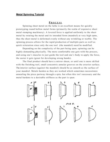
HVL/cc Medium Voltage, Metal-Enclosed SwitchgearGeneral and Application InformationOutdoor Single Switch or Multiple Section Switchgear consists of medium-voltage components ina NEMA Type 3R enclosure. Access is through a gasketed, front bulkhead-type door. The enclosure isdesigned so that the sheared edges of the steel are not exposed. The equipment is furnished with aformed steel channel base and polyester-powder paint finish. Outdoor Single SectionHVL/cc Medium Voltage,Metal-EnclosedSwitchgearRoof sloped to rear for precipitation runoffRemovable operating handles are enclosedFormed steel baseFull-height, gasketed outer front doors11-gauge steel enclosure per ANSI C37.20.3Removable split rear panelsStrip heaters in each switch sectionDoor-stay rods to hold outer-hinged doors in open positionHVL/cc Load Interrupter Switch Construction Sealed-for-life epoxy switch enclosureRotary double break interrupting principleInterruption inside sealed enclosureLow SF6 pressure (5.8 PSI). The switch is capable of interrupting load current at 0 PSIG ( 17.5 kV)Low SF6 pressure (22 PSI). The switch is capable of interrupting load current at 0 PSIG (25.8–38 kV)Maintenance-free contactsTwo viewing ports to view the main switch contacts and optional ground switch contacts from thefront panelTerminalOperating ShaftShaft d ContactsTerminal8 1999–2004 Schneider Electric All Rights Reserved07/2004
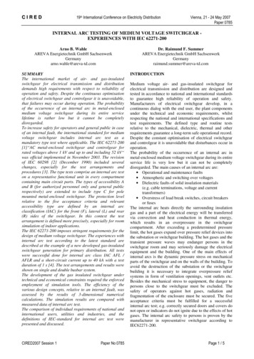
HVL/cc Medium Voltage, Metal-Enclosed SwitchgearGeneral and Application InformationGas TightnessThe HVL/cc switch has been designed and tested for a leakage rate that is less than 3 x 10⁻⁶ bar.cm3per second. The leakage rate will not exceed 0.1% of the total volume of the gas per year over theexpected life of the switch.Mean Time To Failure (MTTF)The HVL/cc switch was introduced globally in 1990. According to the total number of installed switchessince 1992 (over 250,000), the corresponding MTTF is approximately 4,300 years.Typical Life of HVL/cc–600 A, (a) 25.8 & 38 kV, (b) 5.5 & 15 kVNumber of ent Interrupted (Amperes)07/20049 1999–2004 Schneider Electric All Rights Reserved
HVL/cc Medium Voltage, Metal-Enclosed SwitchgearGeneral and Application InformationOperating PositionsContacts in closed position Closing is high-speed and independent of the userSwitch meets all ANSI requirementsContacts in open position ClosedMoving contacts isolated from fixed contacts by SF6 gasGap designed to withstand the recovery voltageContacts in grounded position Closing is high-speed and independent of the userGrounding switch has full fault-making capabilityThe HVL/cc switch with the optional internal ground switch uses sulphur hexaflouride gas (SF6) forinsulation and interrupting. The live parts are contained in a sealed-for-life insulated enclosure. Thisswitch offers remarkable characteristics including:Open Maximum operating reliabilityLow gas pressure – 5.8 PSI 17.5 kV; 22 PSI at 25.8–38 kVMaintenance-free contactsHigh electrical enduranceSequence of Operation—Opening the Switch (for switches equipped with an OTM)In the closed position, the main switch blades are engaged on the stationary contacts. The circuitcurrent flows through the main blades. Live line indicators (LLIs) on the front mechanism cover willindicate that voltage is present on the circuit.GroundedInsert the removable switch operating handle into the lower operating slot on the front mechanismcover and rotate the handle counterclockwise towards the open symbol on the cover. After the springsbecome fully charged, they will toggle over the dead-center position and discharge their stored energyto the switch operating mechanism. The speed of the operating mechanism is independent of thespeed of the user.The action of the switch operating mechanism forces the main blades off the stationary main contactsin a double-break configuration, thus causing circuit interruption. The mimic bus on the end of theswitch shaft (visible on the mechanism cover) will indicate that the contacts are in theopen/ungrounded position. The LLIs will go out.The exceptional qualities of SF6 gas are used to extinguish the electrical arc. The arc appears whenthe fixed and moving contacts separate. The combination of the current and the magnetic field createdby the current cause arc rotation around the stationary contact. This rotation produces arc extensionand cooling until the arc is extinguished at current zero. After this, the distance between the fixed andmoving contacts is sufficient to withstand the recovery voltage. This system is both simple and sure; italso provides extended electrical endurance due to very low wear on the contacts.Sequence of Operation—Grounding the Switch Main Contacts with Optional GroundSwitchAfter the switch is in the open/ungrounded position, the operating handle can be removed from thelower operating slot and inserted into the top grounding slot. These slots are mechanically interlockedto prevent incorrect operation sequence.Rotate the handle clockwise until the springs become fully charged and toggle over the dead-centerposition. The mechanism forces the main blades into the grounded position. The speed of theoperating mechanism is also independent of the speed of the user, identical to the spring openingsequence. The mimic bus on the end of the switch shaft (visible on mechanism cover) will indicate thatthe contacts are in the grounded position. The front lower access panel can only be removed when theswitch is in the grounded position.10 1999–2004 Schneider Electric All Rights Reserved07/2004
HVL/cc Medium Voltage, Metal-Enclosed SwitchgearGeneral and Application InformationSequence of Operation—Closing the Switch with Optional Ground SwitchThe front lower access panel must be installed and the switch blades removed from the groundedposition (if supplied) before the switch main blades can be closed. Replace the lower front accesspanel and insert the operating handle into the top grounding slot. Rotate the handle clockwise until thesprings become fully charged and toggle over the dead-center position. The mechanism forces themain blades into the open/ungrounded position. The speed of the operating mechanism isindependent of the speed of the user. The mimic bus on the end of the switch shaft (visible on themechanism cover) will indicate that the contacts are in the open/ungrounded position. Because theground switch is immersed in SF6 gas, it has a short-circuit-making capability should a fault be on thecircuit when the switch is operated.After the switch is in the open/ungrounded position, the handle may be removed from the topgrounding slot and inserted into the lower operating slot. These slots are mechanically interlocked tolock out incorrect operation sequence. Rotate the handle clockwise until the springs become fullycharged and they toggle over the dead-center position. The mechanism forces the main blades intothe closed position. The speed of the operating mechanism is also independent of the speed of theuser. The mimic bus on the end of the switch shaft will indicate that the contacts are in the closedposition. The LLIs will indicate that voltage is present on the circuit.When the movable main blades approach the stationary main blades, an arc is established across thediminishing gap. The arc occurs between the tip of the stationary main contacts and the edge of themovable main blades. The arc is short and brief, since the fast-closing blades minimize the arcing time.Spring pressure and the momentum of the fast moving main blades completely close the contacts. Theforce is great enough to cause the contacts to close, even against the repelling short-circuit magneticforces if a fault exists on the circuit.The switch nameplate prominently lists performance ratings, fuse supplied, and equipmentidentification.Motor-operated HVL/cc switches are available for applications requiring remote operation. Used withprogrammable controllers (such as Modicon controllers) or electromechanical relays, motor-operatedswitches may be used in automatic load transfer applications. Low voltage controls will be located inthe top-mounted low voltage compartment.Mechanism Cover Application A, OTM ShownGround SwitchOperating Port(OTM/SEM if equipped)Ground SwitchPadlock ProvisionGroundAnimated Mimic BusCLOSEDENDGROPViewing PortsLive-line IndicatorHVLccTMLOAD CURRENT INTERRUPTER SWITCHGEARCloseSwitch0Padlock ProvisionOpenSMYRNA, TN USASwitch Operating Port07/200411 1999–2004 Schneider Electric All Rights Reserved
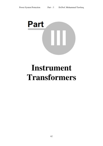
HVL/cc Medium Voltage, Metal-Enclosed SwitchgearTechnical OverviewConstruction Features of Indoor Equipment Strong, 11-gauge steel enclosure is completely grounded Epoxy insulators Electrically and/or mechanically interlocked fuse/cable access panel permitting entry to fuses orcables only when switch is open and grounded (optional). Mechanical interlock also functions forunfused applications Provisions for future expansion Switch interlock (electrical and/or mechanical) to prevent operation of the switch’s main contactswhile the load-side panel is removed Provisions for padlocking the load-side panelANSI 61 paint finish is a TGIC polyester powder applied electrostatically to yield a rugged, durablesurface coatingShatter-resistant safety glass viewing ports for visual assurance of switch blade positionInterlocked, removable front panels for fuse or cable accessSectionalized shipment, when requiredSealed switch enclosure separate from the bus bar compartment and the fuse/cable compartmentby the switch enclosureFull-length ground bus in multiple section enclosuresAccess panel interlock (electrical and/or mechanical) to prevent removal of the load-side panelwhile the switch is closed and/or the ground switch is openKey interlocking is available when requiredThe three, tin-plated copper bus bars are parallel mounted A, B, C, front to rear. 600 and 1200 A mainbus is available. Connection is made to the fuses using field shapers. Bare copper ground bus is bonded to equipment frameHVL/cc ComponentsLow Voltage CompartmentOperating Mechanismwith Mimic Bus CoverLive Line IndicatorsEpoxy Switch Enclosureand Internal Grounding SwitchSquare D FusesEpoxy Insulatorswith Internal CapacitiveDivider Circuits for LLIsFuse/Cable Access Panel12 1999–2004 Schneider Electric All Rights Reserved07/2004
HVL/cc Medium Voltage, Metal-Enclosed SwitchgearTechnical OverviewHVL/cc CompartmentsNOTE: The HVL/cc compartments are shown as shaded areas in thefigures to the left.FrontFrontSwitch Compartment Sealed for life in SF6 gasInterruption in sealed enclosure— No external arcing SwitchCompartmentBusCompartmentFrontUnaffected by the environmentBus CompartmentFront Separate compartment isolated by switch insulation or sheet metalHouses three, parallel-mounted bus barsRating for main bus:— 600 A (standard)— 1200 A (optional)Fuse/Cable CompartmentFuse/CableCompartmentLow Voltage/ControlCompartment Located below switch (Application A) Optional grounding of both sides of fuse available. (With internal groundswitch and LDA–Application A 17.5 kV, 600 A only).FrontFrame-to-frame steel barriersAccessed only after grounding switch is closed. (With ground switchoption)Low Voltage/Control Compartment MechanismCompartmentSeparate low voltage and control compartmentSpace for metering and control componentsMechanism Compartment Contains operators for switch and optional grounding switch— Optional motor with padlock provisions on control power disconnectswitch— Optional close and open coils Standard LLIs— Externally mounted neon indicating lights (one per phase) Externally accessibleAdditional ComponentsMetering sections for user or power company equipment are available. Theymay be supplied fully equipped with necessary current transformers,potential transformers, meters, and associated devices, or with provisionsonly for installing power company components at the job site.Standardized utility metering sections match the adjacent switchgear andincorporate all the special requirements of the power company.Standard HVL/cc customer meter sections are 29.50 in. (750 mm) wide 17.5 kV and 39.37 in. (1000 mm) wide for 25.8 – 38.0 kV.07/20041313 1999–2004 Schneider Electric All Rights Reserved
HVL/cc Medium Voltage, Metal-Enclosed SwitchgearTechnical OverviewCable TerminationsOn unfused switches, the load cables are connected directly to the terminals of the switch.Transformer cables are connected to the lower fuse holder/field shaper.Cables may have either: simplified terminations for dry-type, one- or three-core cablesheat-shrink ends for dry-type or paper-insulated cables.With basic equipment, the maximum cable sizes are: 4–500 kcmil/phase for 1200 A incoming or outgoing terminal chambers2–500 kcmil/phase for 600 A incoming or outgoing switch cubicles2–1/0 AWG/phase for switches incorporating fuses and direct coupled to transformers.The optional grounding switch must be in the grounded position before the fuse/cable compartmentcan be accessed. The reduced depth of the cubicle allows for easy connection of all phases. Ananti-rotation stud is incorporated in the field shaper. Schneider Electric-supplied lugs must be usedwith this switchgear.Padlock provisions are standard for: load interrupter switchoptional grounding
HVL/cc Medium Volta ge, Metal-Enclosed Switchgear General and Application Information General Square D-brand Medium Voltage, Metal-Enclosed Switchgear functions as a prime component of medium voltage, electrical power distribution systems providing necessary switching and overcurrent


![[ ANSI C37.20 and NEMA SG-5 ]](/img/5/metal-clad-en.jpg)