Transcription
CIRED19th International Conference on Electricity DistributionVienna, 21 - 24 May 2007Paper 0785INTERNAL ARC TESTING OF MEDIUM VOLTAGE SWITCHGEAR EXPERIENCES WITH IEC 62271-200Arno B. WahleAREVA Energietechnik GmbH e international market of air- and gas-insulatedswitchgear for electrical transmission and distributiondemands high requirements with respect to reliability ofoperation and safety. Despite the continuous optimisationof electrical switchgear and controlgear it is unavoidable,that failures may occur during operation. The probabilityof the occurrence of an internal arc in metal-enclosedmedium voltage switchgear during its entire servicelifetime is rather low but it cannot be completelydisregarded.To increase safety for operators and general public in caseof an internal fault, the international standard for mediumvoltage switchgear includes internal arc test as amandatory type test where applicable. The IEC 62271-200[1]“AC metal-enclosed switchgear and controlgear forrated voltages above 1 kV and up to and including 52 kV“was official implemented in November 2003. The revisionof IEC 60298 [2] (December 1990) included severalchanges, especially for the test arrangements andprocedures [3]. The type tests comprise an internal arc teston a representative functional unit in every compartmentcontaining main circuit parts. The types of accessibility Aand B (for authorized personnel only and general publicrespectively) are extended to include type C for polemounted metal-enclosed switchgear. The protection levelrelative to the five acceptance criteria and relevantaccessibility type are defined by an internal arcclassification (IAC) for the front (F), lateral (L) and rear(R) sides of the switchgear. In this context the testarrangement is defined more precisely, especially for roomsimulation of indoor applications.The IEC 62271-200 imposes stringent requirements for thedesign of medium voltage switchgear. The experiences withinternal arc test according to the latest standard aredescribed at the example of a new developed gas-insulatedswitchgear generation for primary distribution. All testswere successful done for internal arc class IAC AFL /AFLR and a short-circuit current up to 40 kA with a testduration of 1 s [4]. The test arrangements and results wereshown on single and double busbar system.The development of the gas insulated switchgear undertechnical and economical constraints required the enforcedemployment of simulation tools. The efficiency of thevarious design concepts, relative to an internal fault, wasassessed by the results of 3-dimensional numericalcalculations. The simulation results are compared withmeasured data of internal arc test.The comparison of individual requirements of national andinternational users, utilities and industries, and thedefinitions of IEC-standard for internal arc test werepresented and discussed.CIRED2007 Session 1Paper No 0785Dr. Raimund F. SummerAREVA Energietechnik GmbH DUCTIONMedium voltage air- and gas-insulated switchgear forelectrical transmission and distribution are designed andtested in accordance to national and international standardsto guarantee high reliability of operation and safety.Manufacturers of electrical switchgear develop, in acontinuous dialog with the end user, the plant componentsunder the technical and economic requirements, whilstrespecting the national and international specifications andtest requirements. The defined type and routine testsrelative to the mechanical, dielectric, thermal and otherrequirements guarantee a long-term safe operational record.Despite the constant optimisation of electrical switchgearand controlgear it is unavoidable that disturbances occur inoperation.The probability of the occurrence of an internal arc inmetal-enclosed medium voltage switchgear during its entireservice life is very low but it can not be completelydisregarded. The main causes of an internal arc are: Operational and maintenance faults Atmospheric and switching over voltages Dielectric faults of solid insulation materials(e.g. cable terminations, voltage and currenttransformers) Overstress of load break switches, circuit breakersor fusesThe internal arc heats directly the surrounding insulationgas and a part of the electrical energy will be transferredvia convection and heat conduction in thermal energy,which results in an overpressure in the switchgearcompartment. After exceeding a predetermined pressurelimit, the hot gases expand over pressure relief devices intothe substation or switchgear building. The hot gases and thetransient pressure waves may endanger persons in theswitchgear room and may seriously damage the electricalequipment and the building. One of the main effects ofinternal arcs is the dynamic pressure stress on mechanicalparts of the switchgear and on the walls of the building. Toavoid the destruction of the substation or the switchgearbuilding it is necessary to integrate overpressure reliefsystems in form of ventilation openings, vent outlets etc.Besides the mechanical stress to equipment, the danger topersons close to the switchgear must be excluded. Thesafety of operators against hot gases, radiation andfragmentation of the enclosure must be secured. The fiveacceptance criteria must be fulfilled for a successfulinternal arc test; e.g. correctly secured doors and covers donot open or indicators do not ignite due to the effects of hotgases. The internal arc safety to persons is proven by themanufacturer in representative switchgear according toIEC62271-200.Page 1 / 5
CIRED19th International Conference on Electricity DistributionEXPERIENCES WITH IEC 62271-200 IN CASE OFINTERNAL ARC TESTINGThe current valid international standard for metal-enclosedswitchgear and controlgear for rated voltages from 1 kVand up to and including 52 kV is written in the first editionIEC 62271-200 from November 2003. The current standardis the result of the revision of IEC 60298 from December1990 [3]. In 2006, the second edition of IEC 62271-200was prepared by subcommittee SC17C and the project wasassigned to maintenance team 14. The target date for thecommittee draft (CD) is proposed for June 2007, whichwill be followed one year later by committee draft forvoting (CDV) in June 2008. The final draft internationalstandard (FDIS) is foreseen in June 2009 and the date ofpublication as an international standard will be inDecember 2009.The major change of IEC 62271-200, edition 1.0, is therevision of new definitions and classifications of equipmentof metal-enclosed switchgear and controlgear. Other mainmodification are the introduction of internal arc classes(IAC) and the description of methods for testing. Thequalification of a new design of a metal-enclosedswitchgear and controlgear is done by several type tests.The personal protection due to an internal fault in mediumvoltage metal-enclosed switchgear became in IEC 62271200 a significant higher importance. The internal arc test,as a mandatory type test, is intended to verify theeffectiveness of the design in protecting persons in case ofan internal arc and is defined in internal arc class (IAC).This class is intended to ensure a tested level of protectionto persons in the vicinity of the electrical equipment innormal operating conditions and with the switchgear andcontrolgear in normal service position. The internal arcclass makes allowance for internal overpressure acting oncovers, doors, etc., and it also takes into consideration thethermal effects of arc or it roots on the enclosure and ofejected hot gases and glowing particles. The definition ofinternal arc classes (IAC) describes mainly the types ofaccessibility, test arrangement, test procedure andacceptance criteria.The types of accessibility A and B (for authorisedpersonnel only and general public, respectively) areextended to type C for pole mounted metal enclosedswitchgear. The accessibility of type C is restricted toinstallation out of reach. The accessibility of type A and Bis defined more precise, by defining different sides of theenclosure as front (F), lateral (L) and rear (R) side.The test arrangement shall include fully equipped testobjects. Mock-ups of internal components are permittedwith the same volume and external material as the originalitems and with no influence on the main and earthingcircuit. The test shall be performed in every compartmentof the switchgear and controlgear containing main circuits.Extensible modular units shall be tested in allcompartments at the end of a minimum arrangement of twounits. All the tests shall be done on representativefunctional units. In the case of fluid-filled compartments,other than SF6 (sulphur hexafluoride), the test shall bemade with the original fluid at its rated filling conditions.CIRED2007 Session 1Paper No 0785Vienna, 21 - 24 May 2007Paper 0785The replacement of SF6 with air is permitted, but thepressure rise will be different. The pressure will rise morerapidly in air, because of the difference heat capacities.Experimental results show that the maximum overpressurein air is always higher than in sulphur hexafluoride at sametest conditions. For example, tests of a compartment with agas volume of ca. 0,08 m3 and a current of 31.5 kA showedan increase of the maximum pressure by 24 %. Thereforethe mechanical stress of the metal-enclosed switchgear isfor internal arc test in air higher than in SF6 and guaranteesmaximum protection with respect to rupture anddeformation of the tested compartment.The room simulation and the arrangement of the test objectare clearly defined; the room shall be represented by afloor, a ceiling, and two walls perpendicular to each other.The minimum distance between the ceiling and the upperpart of the switchgear and controlgear shall be 600 mm 100 mm. Respectively the minimum height of the ceilingshall be 2000 mm from the floor for test objects with aheight of less than 1500 mm. For lower clearances to theceiling, the manufacturer may carry out an additional test.In many cases, switchgear buildings or substations inutilities or industries are optimised also to minimumdimensions with respect to costs. Some users require verysmall building heights of less than 2500 mm, e.g. walkablecompact substations and container. The standardiseddistance of 600 mm between the ceiling and the upper partof the switchgear, however, does not meet the technicalrequirements of the national and international market; amodification of this specification may be reasonable.The lateral wall shall be placed at 100 mm 30 mm fromthe lateral side of the test specimen. The manufacturer maycarry out an additional test with higher clearances to thelateral wall, in order to assess the criteria for installationconditions. From the technical view, testing with aminimum distance of 100 mm fulfills the criteria. Thepressure stress outside the switchgear compartment isrelated to the volume, which is available for expansion.The definition of the rear wall depends on the type ofaccessibility. The employment of exhaust ducts to guidegenerated hot gases during the internal arc test, shall betested with the minimum cross-section dimensions,location and output features of the ducts, like flaps or grid.The output end of the exhausting ducts shall be al least2000 mm away from the tested switchgear and controlgear.An additional remark on security of the personal protectionnear the output is missing. A definition for hot gas flowdirections into the surrounding with respect to personalsafety can be helpful.The material, fixation, and arrangement of the indicatorsare defined in detail to assess the thermal effect of thegases. The indicators shall be placed on a mounting rack ateach accessible side at distances depending on the type ofaccessibility. To simulate the position and work clothes ofauthorised operators (accessibility type A) the distance ofindicators to switchgear and controlgear shall be 300 mm 15 mm. Indicators shall be fitted vertically at all accessiblesides up to a height of 2000 mm, arranged in acheckerboard pattern so that 40 - 50 % of the area iscovered. The horizontal indicators shall be arranged to aheight of 2000 mm above the floor and covering the wholePage 2 / 5
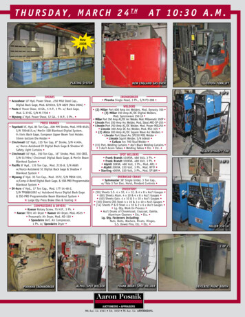
CIRED19th International Conference on Electricity Distributionarea between 300 mm and 800 mm from the test object;when the ceiling is placed at a height of 2000 mm abovethe floor, no horizontal indicators are necessary. Thearrangement of the horizontal indicators shall be in thesame way as the vertical ones. The arrangement ofaccessibility type B shall be assessed against theconsequence of an internal arc fault for the general public.The main difference between accessibility type A and B isthe reduction of the distance between the vertical andhorizontal indicators and the enclosure to 100 mm 5 mm.The horizontal indicators shall be arranged to a height of2000 mm above the floor and covering the whole areabetween 100 mm and 800 mm from the metal-enclosedswitchgear and controlgear. If the height of the test objectis lower than 2000 mm, vertical and horizontal indicatorsshall be placed at a distance of 100 mm 5 mm higherrespectively direct on the top cover.The internal arc test shall be carried out three-phase forthree-phase systems. The short-circuit current appliedduring the test corresponds to the rated short-timewithstand current. It may be lower if specified by themanufacturer. The value of the peak current shall be 2.5times of the rated current for frequencies up to 50 Hz and2.6 times for frequencies up to 60 Hz. The manufacturershall define the duration of the test. Standard recommendedvalues are 1 s, 0.5 s and 0.1 s.The energy feeding direction is described in detail for eachcompartment of the switchgear and controlgear. The arcinitiation shall be done between all three phases or betweenone phase and earth of segregated phase conductors. Thepoint of initiation in the compartment shall be located at thefurthest accessible point from the supply, within thecompartment under test. In case of segregated phaseconductors, the arc ignition shall be between one phase andearth at gaps or joining surfaces between the insulation ofinsulation-embedded parts.The initiation of the arc in a cable compartment shall bedone between two phases at the plugs without insulationand the third phase shall be provided with a plug-inconnector as can be used in service and able to beenergised.The class designation of the tested switchgear andcontrolgear shall be included to the nameplate, e.g.:Class IAC AFLRInternal arc: 40 kA 1 sThe example describes a qualified metal-enclosedswitchgear and controlgear according to the IAC class. Theaccessibility type is A for authorised personnel only on thefront, lateral and rear side; the short-circuit current is 40 kAand the test duration is 1 s.The defined internal arc test does not consider all effects ofan internal fault. For example the dynamic mechanicalstress on the walls of the switchgear room or building dueto the overpressure is not considered. The standard does notprovide rules how to calculate the effect of theoverpressure when the hot gases will rupture over pressurerelief devices inside the switchgear room or building. It isonly written, that it should be taken into considerationwhen designing the installation.The IEC62271-200 enforces high requirements for theCIRED2007 Session 1Paper No 0785Vienna, 21 - 24 May 2007Paper 0785design of metal-enclosed medium voltage switchgear andcontrolgear. The end user of such qualified switchgear andcontrolgear can be sure that the protection against aninternal fault for the operator and for the general public isvery high.DEVELOPMENT OF A NEW GIS GENERATIONACCORDING TO IEC62271-200 WITH RESPECTTO INTERNAL ARC TYPE TESTSThe following chapter describes the development of a newgas-insulated switchgear generation GHA [4] for primarydistribution for internal arc testing according to IEC 62271200. All tests were successful passed for internal arc classIAC AFL / AFLR and a short-circuit current up to 40 kA(104 kA peak) with a test duration of 1 s.The metal-enclosed gas insulated switchgear GHA isperformed in a compact modular design with the possibilityof extensibility on both sides. The rated voltage is up to40.5 kV and a rated current up to 2500 A; the busbarsystem is available in single (SBB) and double busbar(DBB). Fig. 1 presents the switchgear and controlgearGHA with circuit breaker (vacuum interrupter), outer coincable connection and double busbar.Fig. 1: Gas insulated switchgear GHA, 40.5 kV, 2500 A,40 kA 3 s, Double busbarThe spatial and temporal distributions of pressure andtemperature and fluid velocities, that result from an internalarc fault, are determining parameters for many aspects inthe mechanical design. For that reason, various 3-Dsimulations of the arc test conditions were performed in thedevelopment process of the new AREVA product GHA.Simulations and type tests were performed for a threephase ignition with the rated short circuit current in thebusbar compartment (iBB) and inside the circuit breakercompartment (iCB), and a two-phase ignition with 87 % ofthe rated current between two adjacent phases at the cablesPage 3 / 5
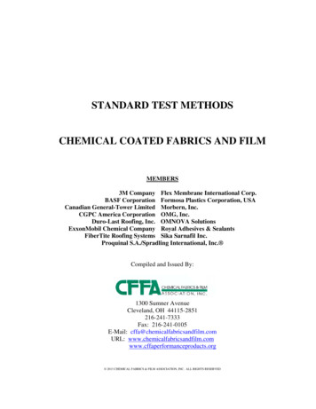
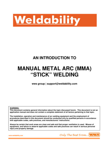
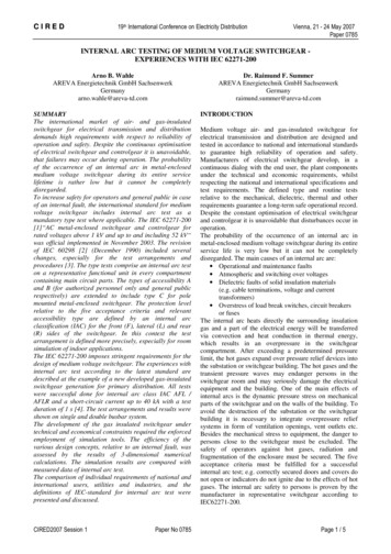
CIRED19th International Conference on Electricity Distributionin the cable compartment (iCC). Here, simulation resultsfor the iCC configuration are presented and are comparedto the test measurement results.When an internal arcing fault occurs, a lighting plasma arcforms a short circuit and an energy of many MJ is releasedwithin a second of time. Most of that energy is transferredto the insulation fluid, which is air in the case presentedhere. The air in the arc region is thereby heated up totemperatures of several thousand Kelvin within somemilliseconds of time, causing the gas to expand explosivelyemitting a pressure wave. At these high temperatures, partof the energy is consumed by dissociation and ionisation ofthe gas molecules; another part of it is emitted as thermalradiation, heating the surrounding material. Progressing intime, an increasing part of the energy is consumed byheating and melting and evaporation of electrode andcladding material, known as the thermal phase. Finally, hotgases at a high pressure, carrying gleaming particles, areemitted to the surrounding. To protect individuals in thevicinity as well as the substation and adjacent functionalunits, the design of the system is challenged to withstandthose effects of a fault instance.Modern simulation tools basically allow to predict theeffects caused by an internal arc. The finite element (FE)method is a suitable tool to address that issue, for itprovides the required spatial and temporal resolution. In FEanalysis, the fluid volumes of a switchgear or controlgearsystem are first divided into a mesh of finite volumes, forwhich then the coupled Navier-Stokes equations are solvedby means of a computational fluid dynamics (CFD) code.For the GHA, three-dimensional FE-models were set upwith a simplified arc model implied. The model geometryfor iCC is shown in Fig. 2.Vienna, 21 - 24 May 2007Paper 0785pressure as well as it’s spatial distribution are of majorinterest for the design with respect to the stress on theswitchgear and the channel. This peak value usually isreached within the first 20 to 30 ms after ignition, or afteropening of a pressure relief device, in systems consisting oftwo functional units. When focussing to the firstmilliseconds, effects in the subsequent thermal phase of theinternal arc fault can be neglected in first approximation.A modified ideal gas model for air was used in thecalculation with a temperature dependent specific heat, thatcovered the dissociation and ionisation energy losses of thegas.An electric arc, which is initiated between the cables withfeeding from the bus bar, will move to the furthest distantend of conductors from the power supply. There, it expandsinto the air volume of the cable compartment, driven bymagnetic forces. The magnetic, electric and thermal forceskeep the arc moving. In simulation, the lighting arc wasmodelled as a volume heat source, that was applied to asmall volume fraction of the cable compartment. Thisvolume fraction resembled an estimate of the volume, intowhich the electric arc most likely will expand to. Since thefocus was on the first milliseconds after ignition and sinceradiation losses as well as a temperature dependent specificheat capacity was considered, there was no need to define apower transfer coefficient, as usually introduced in suchcalculations.The electric power supplied to the arc was calculated fromthe short circuit current as a function of time and a constantvoltage. Fig.3 shows the calculated electric power togetherwith the measured arcing power for iCC. The short-circuitcurrent was 34.8 kA (87 % of 40 kA), in accordance withIEC specification.120MeasurementCalculationel. Power (MW)1008060402000102030405060708090100Time (ms)Fig. 2: CFD model of a system of two GHA single busbarfunctional units with a pressure relief channelThe model resembled a system of two GHA single busbarfunctional units with a pressure relief channel. Thegeometry consisted of the volumes of the cablecompartment and the pressure relief channel. The openingof the channel is at the far end of the 2000 mm lengthexhaust duct, where hot gases are released to the ambienceoutside a container. Cross symbols indicate the pressuremeasurement points.The maximum peak value and the rise time of fluidCIRED2007 Session 1Paper No 0785Fig. 3: Model electric arc power compared to measurementFig. 4 shows the measured pressure together with thecalculated pressure rise at the front door of the cablecompartment. Soon after ignition of the electric arc, there isa steep increase of pressure in the cable compartment. Thefirst peak in this increase is due to the direct incidentpressure wave at the measurement point. While overallpressure still increases by heating of the gas, oscillationsshow up in the pressure curve. These oscillations comefrom reflections of the pressure wave.Page 4 / 5
CIRED200120804000510Vienna, 21 - 24 May 2007Paper 0785had a major impact on the design. Resulting pressurelevels, for example, determined the design of the front doorof the cable compartment and of the joints of the channelsystem, as well as of the interconnection openings.Analysis of the temperature distribution and fluid velocityhelped to decide on need for thermal shielding.Eventually, combining experience with modern simulationtools allowed for successful testing according toIEC 62271-200, wile reducing the need for cost intensivetest cycles.P1 MeasurementP1 Simulation160Pressure (kPa)19th International Conference on Electricity Distribution15Time (ms)202530Fig. 4: Pressure in the cable compartment (iCC)SUMMARYThe calculation reproduced the measurement results wellover the first milliseconds. Since some power losses wereneglected, the pressure rise after the first 20 ms isoverestimated. Reflections of the pressure wave are notfully resolved in the simulation, due to geometricsimplifications of the cable compartment geometry and theinterior components.With increasing distance from the source, the peaks in thepressure course become less pronounced, because ofdamping and superposition of pressure waves. Fig. 5 showsthe pressure at the top of the channel of the tested unit.Experiences with IEC 62271-200 in case of internal arctesting of medium voltage switchgear were presented. Thecomparison of individual requirements of national andinternational users, utilities and industries, and thedefinitions of the IEC-standard for internal arc test werediscussed. The need for modern simulation methods in thedevelopment of a new product was stressed, in order tocomply with the stringent requirements of the newstandard. Simulation and type test results for one of theinternal arc tests according to the standard were presentedand compared.60P3 MeasurementP3 SimulationPressure (kPa)50REFERENCES403020100051015Time (ms)202530Fig. 5: Pressure at the top of the channelThe design of the channel modules provided openingsinterconnecting the modules and also to a channel volumeat the lateral side walls of the system. This allowed forattenuated expansion of the pressure wave throughout thechannel system while reducing pressure load at the originunit. Fig. 6 presents the pressure at the tapering of theexhaust duct.Pressure (kPa)40[1] IEC 62271-200, first edition, 2003-11, “AC metalenclosed switchgear and controlgear for ratedvoltages above 1 kV and up to and including 52 kV”[2] IEC 60298, edition 3.0, 12/1990, “AC metal-enclosedswitchgear and controlgear for rated voltages above 1kV and up to and including 52 kV”[3] A. Wahle, S. Ruhland, 2003, “Influence of the newIEC 60298 with respect to the design of metalenclosed medium voltage switchgear”, Session 1,CIRED 17th International conference on electricitydistribution, Barcelona, Spain[4] www.areva.comP6 MeasurementP6 Simulation3020100051015Time (ms)202530Fig. 6: Pressure at the tapering of the exhaust ductSimulations were carried out in the development stage andCIRED2007 Session 1Paper No 0785Page 5 / 5
switchgear and controlgear is done by several type tests. The personal protection due to an internal fault in medium voltage metal-enclosed switchgear became in IEC 62271-200 a sig