Transcription
Power System ProtectionPart – 3Dr.Prof .Mohammed TawfeeqInstrumentTransformers26
Power System ProtectionPart – 3Dr.Prof .Mohammed TawfeeqPower System protectionDr. Mohamad TawfeeqInstrument TransformersInstrument Transformers CT – Current Transformer CurrentScaling Isolation VT– Voltage Transformer VoltageScaling Isolation1.Current Transformers Current and voltage transformers are responsible forscaling primary system signals. Typical nominal secondary values are 5 A and 1 A forcurrent transformers and 110 V for voltage transformers. Conventional magnetic current and voltage transformersare still in wide use in power systems. For voltage levelsgreater than 230 kV, we substitute capacitive-coupledvoltage transformers (CCVT) for VTs.CT saturation andbad transient response of CCVTs create protectionproblems. New trends in current and voltage transducers are lowpower-output current and voltage transformers (recentlyincluded in an IEC Standard) and magneto-optic currentand voltage transducers (MOCT and MOVT). MOCTs usethe Faraday Effect, and MOVTs can use either the Faradayor the Pockels effect.26
Power System ProtectionPart – 3Dr.Prof .Mohammed TawfeeqPrinciples of Current TransformersThe initial problem was how to connect a low-voltage device to the high-voltagesystem and have the ability to handle large fault currents (kilo-Amps). How can wemake the relay measure the currents flowing in the high-voltage system in order todetect these faults?The solution consists of using a special type of transformer, called a currenttransformer.The main parts of a current transformer are: Iron core Secondary winding Primary conductor External insulationSome current transformers do not have a primary conductor. In those cases theprimary is the line or bus itself. Sometimes the core and its secondary winding aredirectly installed in the bushing of the circuit breakers or transformers. These CTs arecalled “bushing CTs”.Some current transformers may have a primary that consists of several turns.Typically there are no more turns than the natural, which is equivalent to say that theprimary number of turns is 1.The total load connected to the CT terminal (g and h in this case) is called “burden”.Ideally, the secondary current of a CT is perfectly proportional to the primary current.It will be shown later that in reality this is sometimes not true.26
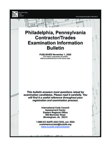
Power System ProtectionPart – 3Dr.Prof .Mohammed TawfeeqCore and Secondary Winding ExampleHigh-Voltage CT Example26
Power System ProtectionPart – 3Dr.Prof .Mohammed TawfeeqNote that in all cases there are polarity marks. Thefollowing conventions are used to mark thereference for AC currents:ANSI: Polarity marksIEC: P1, P2, S1, S2VDE: K, L, k, l22
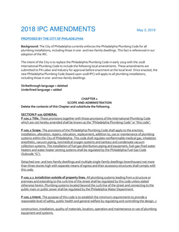
Power System ProtectionPart – 3Dr.Prof .Mohammed TawfeeqCT Common ConnectionsThese are the two of the most common connections of currenttransformers in three phase systems.At the left, the “Y” connection provides the line currents at thesecondary.At the right, the “ ” connection provides the difference currents(delta currents) to the secondary loads.26
Power System ProtectionPart – 3Dr.Prof .Mohammed TawfeeqCurrent Transformer Ratio (CTR)The Current Transformer Ratio, CTR, expressed as a fraction, isthe ratio between the magnitudes of the primary and thesecondary current for ideal working conditions of the currenttransformer. Denominator Typically:is the Secondary Rated Current1 A or 5 A NumeratorIs Not Always the Primary Rated Current26
Power System ProtectionPart – 3Dr.Prof .Mohammed TawfeeqCurrent Transformer Equivalent Circuit26
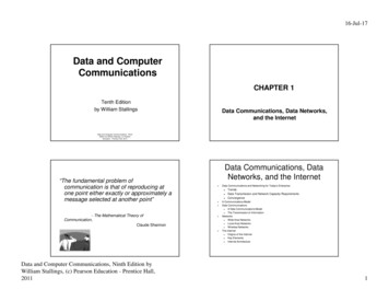
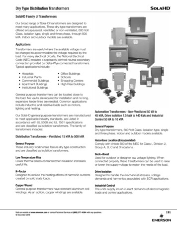
Power System ProtectionPart – 3Dr.Prof .Mohammed TawfeeqCT Performance CalculationsThe performance of a C.T may be found from two approaches :1. The formula method.2. The saturation curve method.2- The saturation curve and error method.The relation between Es and Ie is not linear like the relation shown in the Fig.1due to the saturation of C.T core. Therefore the C.T. has ratio error.Fig.1 Magnetizing curve67
Power System ProtectionPart – 3Dr.Prof .Mohammed Tawfeeq The deviation of Is’ from Is is called the C.T error, and can be expressedas a percentage.C.TerrorI s I s'I x100% e x100%IsIsWhere:Is –Is’ IeIs: Total current in the CT secondaryIs’: Current due to the CT loadExample:Assume that a C.T has rated current ratio of 500/5 A. The impedance ofthe secondary winding Z2 0.242 Ω, and the burden impedance ZB 0.351 Ω .The core area A 0.00193 m2. The C.T must operate atmáximum primary current of 10 kA.If the frequency is 60 Hz and thecore is built from silicon steel:(a) Determine whether or not the C.T will saturate.(b) Determine the C.T error.SolutionIs 10,000 x (5/500) 100 AIf we neglect the excitation current Ie.Is’ Is 100 A.Es Is (ZB Z2) 100 x (0.351 0.242) 59.29 VEs 4.44 * f * N2 * A * BmSo:Bm 59.29 1.15T5004.44 x60 xx0.0019355As we know that the lower limit for the silcion steel saturation isBm 1.2T Hence the C.T will not saturate.From the saturation curve the core corrsponding Ie for Es 59.29 Vis Ie 0.1 A.67
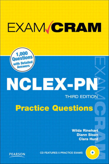
Power System ProtectionPart – 3Dr.Prof .Mohammed Tawfeeq'C.TerrorI0.1% e x100% x100% 0.1%Is100Saturation Curve for Silicon Steel Used in CurrentTransformer Cores for different CTRs.66
Power System ProtectionPart – 3Dr.Prof .Mohammed TawfeeqCT Classes and accuraciesAccuracy ClassClass% error0.10.20.51.05P10P 0.1 0.2 0.5 1.0 1 3ApplicationsMeteringProtectionC.T specifications: A rated burden at rated current or (VA). An accuracy clases (ALF) accuracy limit factor an upper limit beyond which the accuracy isnot guaranteed.Example:1. 15 VA clases 0.5 mettering C.T2. 15 5p 20 protection C.TRated burden 15VAAccuracy class 5pALF 20 (20 times the rated current)66
Power System ProtectionPart – 3Dr.Prof .Mohammed TawfeeqPower System protectionDr. Mohamad TawfeeqInstrument Transformers2.Voltage TransformersVoltage transformers are connected across the points at which the voltageto be measured.Types of voltage Transformers:There are three main types of voltage transformers: Magnetic voltage transformers (ordinary two winding type – usedfor L.V. and M.V). Capacitive Voltage Transformers (CVT), used for high and extrahigh voltages. Magneto—optic voltage transformers (new ).2.1 Magnetic Voltage Transformer (VT)LineVs 110 or 12066
Power System ProtectionPart – 3Dr.Prof .Mohammed TawfeeqVT Equivalent CircuitReferred to the Secondary Side2.2 Capacitive Voltage Transformers (CVT)There are two types of CVTs: Coupling capacitor voltage transformer Capacitor – bushing voltage transformerThese types are shown in figure below:Figure : Capacitor voltage transformers: (a) coupling-capacitor voltage divider(b) capacitance-bushing voltage divider .66
Power System ProtectionPart – 3CVT equivalent circuit62Dr.Prof .Mohammed Tawfeeq
Part – 3Power System ProtectionDr.Prof .Mohammed TawfeeqVT error : Errors in magnitude can be calculatedfrom :Error VT {(n Vs - Vp) / Vp} x 100%.Table : Voltage transformers error maryvoltage0.8 Vn , 1.0Vn and 1.2Vn0.5 VnVnVoltageerror( %)Phase error( 040.080.00.22.02.03.080.080.080.0120.0Vn Nominal voltage66
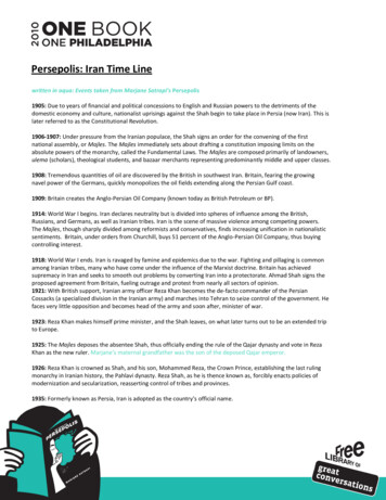
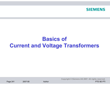
Power System ProtectionPart – 3Dr.Prof .Mohammed TawfeeqVT connections(b) delta – wye connection(a) Open delta connection(c) wye—wye connection66
Coupling capacitor voltage transformer Capacitor – bushing voltage transformer These types are shown in figure below: Figure : Capacitor voltage transformers: (a) coupling-capacitor voltage divider (b) capacitance-bushing voltage divider . Power System Protection Part 3 Dr.Prof .Mohammed Tawfeeq 62 CVT equivalent circuit . Power System Protection Part 3 Dr.Prof .Mohammed Tawfeeq