Transcription
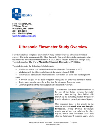
Phased Array Ultrasonic TechnologyTheory(PAUT Inspection)Principle (1/5)ULTRASONIC WAVESThese are the mechanical vibrations induced in an elastic medium (thetest piece) by the piezocrystal probe excited by an electrical voltage.Typical frequencies of ultrasonic waves are in the range of 0.1 MHz to 50MHz. Most of the industrial applications require frequencies between0.5 MHz to 15 MHz.Most conventional ultrasonic inspections use monocrystal probes withdivergent beams. The ultrasonic field propagates along an acoustic axiswith a single refracted angle. The divergence of this beam is the only"additional" angle, which might contribute to detection and sizing ofmiss-oriented small cracks.Assume the monoblock is cut in many identical elements, each with awidth much smaller than its length. Each small crystal may beconsidered a line source of cylindrical waves. The wavefronts of the newacoustic block will interfere, generating an overall wavefront.The small wavefronts can be time-delayed and synchronized for phaseand amplitude, in such a way as to create an ultrasonic focused beamwith steering capability.www.tcradvanced.com
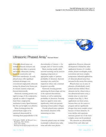
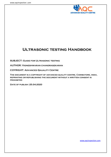
Phased Array Ultrasonic TechnologyTheory(PAUT Inspection)Principle (2/5)T H E M A I N F E AT U R E O F P H A S E D A R R AY U LT R A S O N I CTECHNOLOGY AND PHASED ARRAY ULTRASONIC TESTING is thecomputer controlled excitation (amplitude and delay) of individualelements in a multi-element probe. The excitation of piezo-compositeelements can generate an ultrasonic focused beam with the possibilityof modifying the beam parameters such as angle, focal distance andfocal spot size through software. The sweeping beam is focused and candetect in specular mode the miss-oriented cracks. These cracks may belocated randomly away from the beam axis. A single crystal probe, withlimited movement and beam angle, has a high probability of missingmiss-oriented cracks, or cracks located away from the beam axis (seeFigure 1).www.tcradvanced.com
Phased Array Ultrasonic TechnologyTheory(PAUT Inspection)Principle (3/5)www.tcradvanced.com
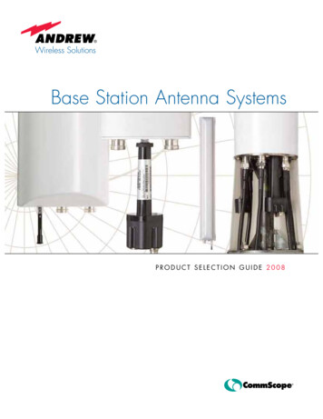
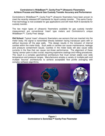
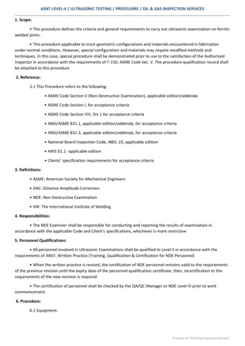
Phased Array Ultrasonic TechnologyTheory(PAUT Inspection)Principle (4/5)To generate a beam in phase and with a constructive interference, thevarious active probe elements are pulsed at slightly different times. Asshown in Figure 2, the echo from the desired focal point hits the varioustransducer elements with a computable time shift. The echo signalsreceived at each transducer element are time-shifted before beingsummed together. The resulting sum is an A-scan that emphasizes theresponse from the desired focal point and attenuates various other echoesfrom other points in the material. During transmission, the acquisition instrument sends a trigger signal to thephased array instrument. The latter converts the signal into a high voltagepulse with a pre-programmed width and time delay defined in the focal laws.Each element receives one pulse only. This creates a beam with a specific angleand focused at a specific depth. The beam hits the defect and bounces back. The signals are received, then time-shifted according to the receiving focal law.They are then reunited together to form a single ultrasonic pulse that is sent tothe acquisition instrument. The delay value on each element depends on the aperture of the phased arrayprobe active element, type of wave, refracted angle and focal depth. There arethree major computer-controlled beam scanning patterns (see also chapter 3and 4): Electronic Scanning: the same focal law and delay is multiplexed across a groupof active elements (See Figure 4); scanning is performed at a constant angleand along the phased array probe length (aperture). This is equivalent to aconventional ultrasonic transducer performing a raster scan for corrosionmapping or shear wave inspection. If an angled wedge is used, the focal lawscompensate for different time delays inside the wedge.www.tcradvanced.com
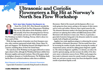
Phased Array Ultrasonic TechnologyTheory(PAUT Inspection)Principle (5/5) Dynamic Depth Focusing or DDF (along the beam axis): scanning is performedwith different focal depths. In practice, a single transmitted focused pulse isused, and refocusing is performed on reception for all programmed depths(see Figure 5). Sectorial Scanning (also called azimuthal or angular scanning): the beam ismoved through a sweep range for a specific focal depth, using the sameelements; other sweep ranges with different focal depths may be added. Theangular sectors may have different values.www.tcradvanced.com
TECHNOLOGY AND PHASED ARRAY ULTRASONIC TESTING is the computer controlled excitation (amplitude and delay) of individual elements in a multi-element probe. The excitation of piezo-composite elements can generate an ultrasonic focused beam with the possibility of modifying