Transcription
IAEA-TECDOC-462ULTRASONIC TESTING OF MATERIALSAT LEVEL 2TRAINING MANUALFOR NON-DESTRUCTIVE TESTING TECHNIQUESA TECHNICAL DOCUMENT ISSUED BY THEINTERNATIONAL ATOMIC ENERGY AGENCY, VIENNA, 1988
ULTRASONIC TESTING OF MATERIALS AT LEVEL 2IAEA, VIENNA, 1988IAEA-TECDOC-462Printed by the IAEA in AustriaJune 1988
FOREWORDThe International Atomic Energy Agency is executingregional projects in the Latin American and Caribbean Regionand the Asia and Pacific Region using the syllabi contained inIAEA-TECDOC-407 'Training Guidelines in Non-destructive TestingTechniques . * which has beenreferenced as being suitable Organisation in the draft standard DP9712, 'The Qualification andCertification of NDT Personnel'.These ultrasonic notes have therefore been preparedessentiallyin accordance with the syllabus for Level2ultrasonic personnel and have been used as the basis for the 80hourmodelLevel 2 ultrasonic regional trainingcoursesconducted by the Asia and and Pacific Project.The notes are theresultofcontributions from a number ofNationalNDTcoordinators in the Asia and Pacific Region who have beenorganising National NDT Training Courses.For guidance it is suggested that the minimum 80hours training recommended by ISO DP9712 be divided as follows;1. General knowledge8 hours2. Terminology»physical principlesand fundamentals of ultrasonics3. Testing techniques and theirlimitations4. Equipment and accessories5. Calibration of the testingsystem8"86""12"6. Specific applications7. Codes, standards,specificationsand procedures12"10"8. Recording and evaluation ofresults109. Special techniques6"
EDITORIAL NOTEIn preparing this material for the press, staff of the International Atomic Energy Agencyhave mounted and paginated the original manuscripts and given some attention to presentation.The views expressed do not necessarily reflect those of the governments of the Member Statesor organizations under whose auspices the manuscripts were produced.The use in this book of particular designations of countries or territories does not imply anyjudgement by the publisher, the IAEA, as to the legal status of such countries or territories, oftheir authorities and institutions or of the delimitation of their boundaries.The mention of specific companies or of their products or brand names does not imply anyendorsement or recommendation on the part of the IAEA.
CONTENTS1.2.INTRODUCTION .111.1. Quality and reliability .1.2. Non-destructive testing (NDT) methods of quality control .1.2.1. Liquid penetrant testing .1.2.2. Magnetic particle testing .1.2.3. Eddy current testing .1.2.4. Radiographie testing method .1.2.5. Ultrasonic testing .1.3. Comparison of different NDT methods .1.4. Destructive versus non-destructive testing .111212131414141719TERMINOLOGY, PHYSICAL PRINCIPLES AND FUNDAMENTALSOF ULTRASONICS .232.1. The nature of ultrasonic waves .2.2. Characteristics of wave propagation .2.2.1. Frequency .2.2.2. Wave length .2.2.3. Velocity .2.2.4. Fundamental wave equations .2.2.5. Ultrasonic waves .2.2.6. Acoustic impedance .2.2.7. Acoustic pressure and intensity .2.3. Types of ultrasonic waves .2.3.1. Longitudinal waves .2.3.2. Transverse or shear waves .2.3.3. Surface or Rayleigh waves .2.3.4. Lamb or plate waves .2.3.5. Velocity of ultrasonic waves .2.4. Behaviour of ultrasonic waves .2.4.1. Reflection and transmission at normal incidence .2.4.1.1. Reflected and transmitted intensities .2.4.1.2. Reflected and transmitted pressures .2.4.2. Reflection and transmission at oblique incidence .2.4.2.1. Refraction and mode conversion .2.4.2.2. Snell's Law .2.4.2.3. First and second critical angles .2.4.2.4. Reflected acoustic pressure at angular incidence .2.5. Piezoelectric and ferroelectric transducers .2.5.1. Piezoelectric effect .2.5.2. Types of piezoelectric transducers .2.5.2.1. Piezoelectric crystal transducers .2.5.2.2. Polarized ceramic transducers .2.5.2.3. Comparison of piezoelectric transducers 14142424546
3.2.6. The characteristics of the ultrasonic beam .2.6.1. The ultrasonic beam .2.6.1.1. Near field .2.6.1.2. Calculation of near field length .2.6.1.3. Far field .2.6.2. Beam spread .2.7. Attenuation of ultrasonic beams .2.7.1. Scattering of ultrasonic waves .2.7.2. Absorption of ultrasonic waves .2.7.3. Loss due to coupling and surface roughness .2.8. Diffraction .4848495052525555565661ULTRASONIC TEST METHODS, SENSORS AND TECHNIQUES .633.1.Basic ultrasonic test methods .3.1.1. Through transmission method .3.1.2. Pulse echo method .3.1.3. Resonance method .Sensors .3.2.1. Ultrasonic probe construction .3.2.2. Types of ultrasonic probes .3.2.2.1. Contact type probes .3.2.2.2. Immersion type probe .Pulse echo testing techniques .3.3.1. Contact type techniques .3.3.1.1. Normal beam techniques .3.3.1.2. Applications of contact type normal beam probes .3.3.1.3. Angle beam techniques .3.3.1.4. Calculation of various distances for angle beam probes .3.3.1.5. Surface wave techniques .3.3.2. Immersion testing techniques .6363646566666868727373737479808383PULSE ECHO TYPE ULTRASONIC FLAW DETECTOR .874.1.8787909192929495953.2.3.3.4.Construction and mode of operation of a pulse echo type flaw detector .4.1.1. Functions of the electronic elements .4.1.2. Operation of a pulse echo type flaw detector .4.2. Scan presentation .4.2.1. A-scan presentation .4.2.2. B-scan presentation .4.2.3. C-scan presentation .4.2.4. Echo amplitude and its control .4.2.4.1. Decibel (dB) unit .5.CALIBRATION OF THE TEST SYSTEM . 995.1. Calibration and reference test blocks . 995.2. Commonly used test blocks . 995.2.1. I.I.W. (VI) calibration block . 995.2.3. Institute of Welding (I.O.W.) beam profile block . 1095.2.3.1. Plotting of beam profile . 110
5.2.4. ASME reference block .5.2.5. Area-amplitude blocks .5.2.6. Distance-amplitude blocks .5.2.7. Blocks .5.3. Checking equipment characteristics .5.4. Methods of setting sensitivity .5.4.1. Distance amplitude correction curves .5.4.2. DOS (distance-gain-size) diagram method .5.4.2.1. Setting sensitivity for a normal beam probe .5.4.2.2. Setting of sensitivity for angle beam probe .5.4.3. Grain response on time base at maximum testing range .5.5. Measurement of attenuation .5.5.1. Longitudinal wave attenuation .5.5.2. Transverse wave attenuation .5.6. Determination of transfer loss for angle beam probes .5.7. Couplants .5.8. Influence of the test specimen on the ultrasonic beam 345.8.1. Surface roughness . 1345.9.5.8.2. Specimen with curved surface .5.8.3. Coated surfaces .5.8.4. Mode conversion within the test specimen .5.8.5. Orientation and depth of flaw .Selection of ultrasonic probe .5.9.1. Choice of ultrasonic beam direction .1351371371371381385.9.2. Choice of probe frequency . 1395.9.3. Choice of probe size . 1406.SPECIFIC APPLICATIONS . 1416.1.Ultrasonic inspection of welds .6.1.1. Types of weld joints .6.1.2. Weld defects .6.1.2.1. Lack of root penetration .6.1.2.2. Lack of fusion .1411411441441446.1.2.3. Slag inclusion .1456.1.2.4. Tungsten inclusion . 1456.1.2.5. Porosity . 1456.1.2.6. Cracks .6.1.2.7. Undercut .6.1.2.8. Excessive penetration .6.1.2.9. Concavity at the root of the weld .6.1.2.10. Lamellar tearing .6.1.3. General procedure for ultrasonic testing of welds .1451461461461471476.1.4. Examination of root in single Vee Butt welds without backing stripin plates and pipes . 1526.1.4.1. Scanning procedure . 1526.1.4.2. Selection of probe angle . 1556.1.5. Examination of weld body in a single Vee Butt weld withoutbacking strip . 1566.1.5.1. Selection of probe angle . 157
6.1.6. Inspection of single Vee Butt welds with backing strips or inserts .6.1.6.1. Welds with EB inserts .6.1.6.2. Welds with backing strips .6.1.7. Inspection of double Vee welds .6.1.7.1. Critical root scan for double Vee welds .1571571591591596.1.7.2. Weld body examination of double Vee welds . 1606.1.8. Examination of T-welds . 1616.1.9. Examination of nozzle welds . 1616.1.9.1. Fully penetrated set on weld . 1626.1.9.2. Partially penetrated set in weld . 1636.1.9.3. Examination of set through nozzle welds . 1636.2. Ultrasonic inspection of forgings . 1646.2.1. Forging defects . 1646.2.2. Testing of semi-finished products: rods and billets .6.2.2.1. Billets .6.2.2.2. Rod materials .6.2.2.3. Use of immersion technique for billet or rod materials .1651651691706.2.3. Tube testing .1726.2.4. Testing of forgings .6.3. Ultrasonic inspection of castings .6.3.1. Defects in castings .6.3.1.1. Shrinkage defects .1741751761766.3.1.2. Defects associated with hindered contraction during cooling . 1796.3.1.3. Defects associated with entrapped gas airlocks . 1817.ULTRASONIC STANDARDS . 1837.1. Commonly used ultrasonic standards . 1837.2. ASME Boiler and Pressure Vessel Code . 1837.3. BS 3923: Part 1: Manual examination of fusion welds in ferritic steels . 1868.RECORDING AND EVALUATION OF RESULTS . 1958.1. Determination of the location, size and nature of a defect . 1958.1.1. Defect location . 1958.1.2. Methods of defect sizing . 1968.1.2.1. 6 dB drop method . 1968.1.2.2. 20 dB drop method . 1978.1.2.3. Flaw location slide . 1998.1.2.3.1. Plotting the beam spread (vertical plane) on theflaw location slide . 2008.1.2.3.2. Using the flaw location slide for flaw locationin welds . 2018.1.2.3.3. Defect sizing using the flaw location slide . 2038.1.2.4. Maximum amplitude technique .8.1.2.5. DOS diagram method .8.1.3. Determination of the nature of a defect .8.2. Ultrasonic test report .204205207210
APPENDIX A. WELDING PROCESSES AND DEFECTS . 217APPENDIX B. CASTINGS AND FORCINGS AND THEIR RELATEDDISCONTINUITIES . 243APPENDIX C. ULTRASONIC PRACTICALS . 255I. Use of ultrasonic flaw detector (functions of various controls on theflaw detector) . 255II. Calibration and use of ultrasonic flaw detector with normal probes . 257El. Comparison of various couplants . 259IV.V.VI.VII.Calibration with angle beam probe .Thickness measurement using the ultrasonic flaw detector .Experiment with mode conversion .Understanding decibel (dB) system .260266267268Vin. Velocity measurement in materials by ultrasonics . 269DC. Beam profile in vertical and horizontal plane . 270X. Checking equipment characteristics .XI. Sensitivity setting using an angle probe and the ASME block .XII. Determination of the attenuation and surface transfer loss correctionbetween the reference calibration block and the test plate .Xu!. Flaw sizing practice .XIV. Procedure for the examination of a single-Vee Butt weldaccording to ASME V .272277278279281
Please be aware that all the Missing Pagesin this document were originally blank pages
1. INTRODUCTION1.1Quality and ReliabilityAn industrial product is designed to perform a certainfunction. The user buys it with every expectation that itwill perform the assigned function well and give atrouble-free service for a reasonable period of time. Thelevel of guarantee or certainty with which a trouble-freeservice can be provided by any product may be termed itsdegree of reliability. The reliability of a machine or anassembly having a number of components depends upon thereliability factors of all the individual components.Most of the machines and systems in the modern day world,for example, railways, automobiles, aircrafts, ships,power plants, chemical and other industrial plants etc,are quite complex having thousands of components on whichtheir operation and smooth running depends. To ensure thereliability of such machines it is important that eachindividual component is reliable and performs its functionsatisfactorily.Reliability comes through improving the quality or qualitylevel of the components or products.A good qualityproduct can therefore be termed one which performs itsassigned function for a reasonable length of time. On theother hand products which fail to meet this criterion andtheir failure or breakdown occurs unpredictablyandearlier than a specified time may be termed as bad or poorquality products.Both these types of products differ inreliability factors or quality levels.The quality of products, components or parts depends uponmanyfactors important among which are the design,material characteristics and materials manufacturing andfabrication "techniques.Quality may be defined intermsof defects and imperfections present in the materials usedfor making the product or the presence of such defects andimperfections in the finished product itself.Manydefects can also be formed in products during service.The nature of these defects differs according to theprocess of its design and fabrication as well as theservice conditions under which it has to work.Aknowledge of these defects with a view to determining themand then minimizing them in a product is essential toachieve a better or an acceptible level of quality.An improvement in the product quality to bring it to areasonable quality level is important in many ways.Itincreases, as already mentioned, the reliability of theproducts and the safety of the machines and equipment andbrings economic returns to the manufacturer by increasinghis production, reducing his scrap levels, enhancing his11
reputation as a producer of quality goods and henceboosting his sales.There is therefore a need to havemethods by which the defects in the products can bedetermined without affecting their serviceability.1.2.Non-Destructive Testing (NOT) Methods Of Quality ControlThe term "Non-destructive testing" is used to describe thematerial testing methods which,without damaging orinfluencing the usefulness of a material or component,give information about its properties.NDT is concernedwith revealing the flaws in an item under inspection. NDTcan not however predict where flaws will develop due tothe design itself.Non-destructive testing (NDT) plays an important role inthe quality control not only of the finished product, butalso of half finished products as well as the initial rawmaterials.NDT can be used at all stages of theproduction process.It can also be used during theprocess of establishing a new technology by monitoringproductquality or when developing a newproduct.Outside the manufacturing field, NDT is also widely usedfor routine or periodic control of various items duringoperationto ascertain that their quality hasnotdeteriorated with use.Themethods of NDT range from the simple tothecomplicated.Visual inspection is the simplest of all.Surface imperfections invisible to the eye may be revealedby penetrant or magnetic methods.If really serioussurface defects are found, there is often little point inproceeding to the more complicated examinations of theinterior by ultrasonics or radiography. The principle NDTmethods are Visual or Optical Inspection, Dye PenetrantTesting, Magnetic Particle Testing, Eddy Current Testing,Radiographie Testing and ultrasonic Testing.The basic principles typical applications, advantages andlimitationsofthese methods with now bebrieflydescribed.A number of other NDT methods exist.These are used onlyfor specialized applications and consequently are limitedin use. Some of these methods are Neutron Radiography,Acoustic Emission, Thermal and Infra Red Testing, StrainSensing, Microwave Techniques, Leak Testing, Holographyetc.1.2.1. Liquid Penetrant TestingThis is a method which can be employed for the detectionofopen-to-surface discontinuities in any industrialproduct which is made from a non porous material. In thismethod a liquid penetrant is applied to the surface of the12
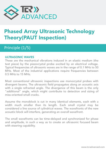
product for a certain predetermined time, after which theexcess penetrant is removed from the surface. The surfaceis then dried and a developer is applied to it.Thepenetrant which remains in the discontinuity is absorbedby the developer to indicate the presence as well as thelocation, sise and nature of the discontinuity.Theprocess is illustrated in Fig .1.1.''. "'- - '.'- Ur """ »"-"--'I' ' '. ,' -. '' ' ' ' " - Zs(a)(b)MMULÜÜLil!/11 ii i !!,'{'f hjirn(fini II . - . . 7-\ Vf ;:-.-."-: .-(d)(c)Figure 1.1Four stages of liquid penetrant process:(a)Penetrant application and seepagethe discontinuity.into(b) Removal of excess penetrant.(c)Application of developer, 2.2. Magnetic Particle TestingMagnetic particle testing is used for the testing ofmaterials which can be easily magnetized.This method iscapable of detecting open-to-surface and just-below-thesurface flaws.In this method the test specimen is firstmagnetisedeitherby using apermanentmagnet,oranelectromagnet or by passing electric current through oraround the specimen.The magnetic field thus introducedinto the specimen is composed of magnetic lines of force.Whenever there is a flaw which interupts the flow ofmagnetic lines of force, some of these lines must exit and13
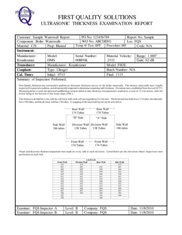
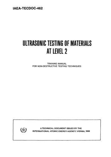
re-enter the specimen.These points of exit and re-entryform opposite magnetic poles.Whenever minute magneticparticles are sprinkled onto the surface of the specimen,these particles are attracted by these magnetic poles tocreate a visual indication approximating the size andshape of the flaw. Fig. 1.2. illustrates the basicprinciples of this method.1.2.3Eddy Current TestingThis method is widely used to detect surface flaws, tosort materials, to measure thin walls from one surfaceonly, to measure thin coatings and in some applications tomeasure case depth.This method is applicabletoelectrically conductive materials only.In the methodeddy currents are produced in the product by bringing itclose to an alternating current-carrying coil.Thealternating magnetic field of the coil is modified by themagnetic fields of the eddy currents.This modification,which depends on the condition of the part near to thecoil, is then shown as a meter reading or cathoderay tubepresentation.Fig.1.3. gives the basic principles ofeddy current testing.1.2.4Radiographie Testing MethodThe radiographie testing method is used for the detectionofinternal flaws on many different materialsandconfigurations.An appropriate radiographie film isplaced behind the test specimen (Fig. 1.4) and is exposedby passing either X-Rays or gamma rays through it. Theintensity of the X-rays or gamma rays while passingthrough the product is modified according to the internalstructure of the specimen and thus the exposed film afterprocessing, reveals the shadow picture of the internalstructure of the product. This shadow picture, known as aradiograph, is then interpreted to obtain data about theflaws present in the specimen.This method is used on awide variety of products such as forgings, castings andweldments.1.2.5. Ultrasonic TestingUltrasonic inspection is a nondestructive method in whichhighfrequency sound waves are introduced into thematerial being inspected.Most ultrasonic inspection isdone at frequencies between 0.5 and 25 MHz - well abovethe range of human hearing, which is about 20 Ha to 20 KHz.The sound waves travel through the material with someattendant loss of energy (attenuation) due to materialcharacteristics or are measured afterreflection at14
Cylindrical tesl objectMagnetrFlux llow-fît' fl iFlaws.!,Crack\l!S.'nil. J*-K -.-ca Kvss5 N/;i linesTest objectThreading barMild steel blockto complete pathFlux linesXj2"\1-'Melal prodsp'- —— Currenl —— .-Bar under lestConductivegauze padsCurrent sourceFigure 1.2EDDYCURRENTMAGNETIC FIELDMAGNETISING COIL X EDDY, j CURRENT '."" Xa) SURFACE PROBEb) ENCIRCLING COILARTICLE.xNt1 INSTRUMENT»—-J—fa)COIL -*1c) INTERNAL COILFigure1.3Eddy current testing.15
RADIATION SOURCETEST SPECIMENRADIATIONDETECTORFigure1.4Arrangement for radiographie testing method.rTransmitterdriverIJ"11 AmplifierReceiver probeTransmitterprobeBoundaryFigure16/ Cathode raytube0 21.5Basic components of andetector.6ultrasonicBflaw
interfaces(pulse echo) or flaws, or are measured at theopposite surface (pulse transmission). The reflected beamis detected an
ultrasonic testing of materials at level 2 training manual for non-destructive testing techniques a technical document issued by the international atomic energy agency, vienna, 1988. ultrasonic testing of materials at level 2 iaea, vi