Transcription
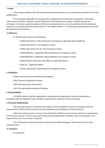
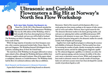
From NDT Technician, Vol. 11, No. 3, pp: 1–5.Copyright 2012 The American Society for Nondestructive Testing, Inc.The American Society for Nondestructive Testingwww.asnt.orgFOCUSUltrasonic Phased Array1 Michael Moles*UUltrasonic phased arrays usemultiple ultrasonic elements andelectronic time delays to generateand receive ultrasound, creatingbeams by constructive anddestructive interference. As such,phased arrays offer significanttechnical advantages overconventional single-probe ultrasonictesting: the phased array beams canbe steered, scanned, swept andfocused electronically.Electronic scanning permits veryrapid coverage of the components,typically an order of magnitudefaster than a single-probemechanical system. Speed increaseslike this can be highly cost-effective.Beam forming permits theselected beam angles to beoptimized ultrasonically byorienting them perpendicular to the* Olympus NDT; 48 Woerd Ave.;Waltham, MA 02543;(416) 831-4428;Michael.moles@olympusndt.comVol. 11, No. 3discontinuities of interest — forexample, lack of fusion in welds.Beam steering (usually calledsectorial scanning) can be used formapping components atappropriate angles to optimizeprobability of detection. Sectorialscanning is also useful forinspections where only a minimalfootprint is possible.Electronic focusing permitsoptimizing the beam shape and sizeat the expected discontinuitylocation, as well as optimizingprobability of detection. Focusingimproves signal-to-noise ratiosignificantly, which also permitsoperating at lower pulser voltages.Overall, phased arrays optimizediscontinuity detection whileminimizing test time.OperationUltrasonic phased arrays are similarin principle to phased array radar,sonar and other wave physicsapplications. However, ultrasonicdevelopment is behind the otherapplications because of a smallermarket, shorter wavelengths, modeconversions and more complexcomponents. Industrial applicationsof ultrasonic phased arrays haveincreased in the twenty-first century.Phased arrays use an array ofelements, all individually wired,pulsed and time shifted. Theseelements can be a linear array, atwo-dimensional matrix array, acircular array or some morecomplex form (Fig. 1). Mostapplications use linear arrays,because these are the easiest toprogram and are significantlycheaper than more complex arraysbecause of fewer elements. Ascosts decline and experienceincreases, greater use of the morecomplex arrays can be predicted.The elements are ultrasonicallyisolated from each other andFOCUS continued on page 2.TNT · July 2012 · 1
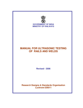
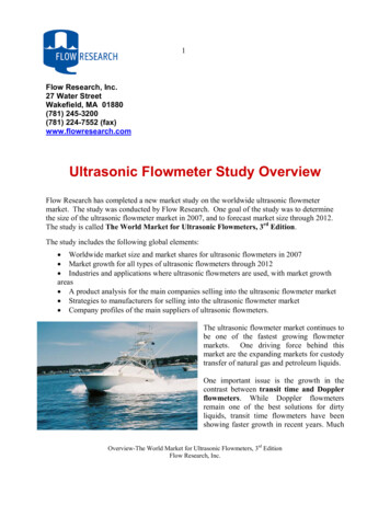
FOCUS continued from page 1.packaged in normal probe housings. The cabling usuallyconsists of a bundle of well shielded micro coaxial cables.Commercial multiple-channel connectors are used with theinstrument cabling.Each element generates a beam when pulsed; multiplebeams constructively and destructively interfere to form awave front. (This interference can be seen, for example,with photoelastic imaging.)2 The phased arrayinstrumentation pulses the individual channels with timedelays as specified to form a pre-calculated wave front. Forreceiving, the instrumentation effectively performs thereverse, that is to say, it receives with precalculated timedelays, then sums the time shifted signal and displays it.This is shown in Fig. 2.The summed waveform is effectively identical to asingle-channel discontinuity detector using a probe with thesame angle, frequency, focusing, aperture and other settings.Figure 2 shows typical time delays for a focused normalbeam and transverse wave. Sample scan patterns are shownin Fig. 3 and are discussed below.Implementation. From a practical viewpoint, ultrasonicphased arrays are primarily a means of generating and(a)(b)123456789 10 11 12 13 14 15 3319932614 264252342010451325 41611112222337385657533554213655243940605958Figure 1. Array types: (a) one-dimensional linear array of16 sensors; (b) two-dimensional matrix array of 32 sensors;(c) sectorial annular array of 61 sensors.2 · Vol. 11, No. 3
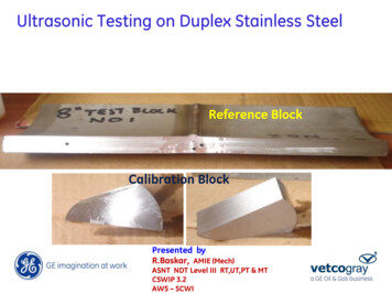
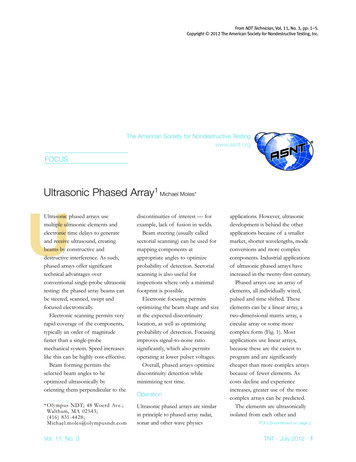
receiving ultrasound; once theultrasound is in the material, it isindependent of generation method,whether generated by piezoelectric,electromagnetic, laser or phasedarrays. Consequently, many of thedetails of ultrasonic testing remainunchanged; for example, if 5 MHz isthe optimum test frequency withconventional ultrasonic testing, thenphased arrays would typically start byusing the same frequency, aperturesize, focal length and incident angle.Besides generating and receivingmulitple waveforms, phased arrays aregood at imaging. Specifically, astandard display shows a twodimensional B- or S-scan whileadditional C-scans can be provided.While phased arrays require welldeveloped instrumentation, one of thekey requirements is good, user-friendlysoftware. Besides calculating the focallaws, the software saves and displaysthe results, so good data manipulationis essential. As phased arrays offerconsiderable application flexibility,software versatility is highly desirable.Phased array inspections can bemanual, semiautomated (that is,encoded but hand-propelled) or fullyautomated, depending on theapplication, speed, budget and otherconsiderations.Although it can be time consumingto prepare the first setup, theinformation is recorded in a file andonly takes seconds to reload. Also,modifying a prepared setup is quick incomparison with physically adjustingconventional probes.Scan TypesElectronic pulsing and receivingprovide significant opportunities for avariety of scan patterns (Fig. 3).Electronic Scans. Electronic scans areperformed by multiplexing the samefocal law (time delays) along an array(Fig. 4). Typical arrays have up to 128elements. Electronic scanning permitsrapid coverage with a tight focal spot.If the array is flat and linear, then thescan pattern is a simple B-scan. If thearray is curved, then the scan patternwill be curved. Electronic scans arestraightforward to program. Forexample, a phased array can be readilyprogrammed to perform corrosionmapping, or to test a weld using45 deg and 60 deg transverse waves,which mimics conventionalmanualinspections.Sectorial Scans (S-Scans). Sectorialscanning is unique to phased arrays.Sectorial scans use the same set ofelements but alter the time delays tosweep the beam through a series of(a)Incidentwave frontPulsesTriggerAcquisitionunitangles (Fig. 5). Again, this is astraightforward scan to program.Applications for sectorial scanningtypically involve a stationary array,sweeping across a relativelyinaccessible component like a turbineblade root, to map out the featuresand discontinuities. Dependingprimarily on the array frequency andelement spacing, the sweep angles canvary from 20 deg up to 80 deg.FOCUS continued on page 4.(a)DelaySensorsResulting wavesurface(b)Applied delaySensorsAngle steeringResulting wave surfaceFigure 3. Schematic time delays (histograms):(a) focused normal beam; (b) focusedtransverse wave.DiscontinuityPhasedarrayunitActive group 161Sensors(b)Reflectedwave frontEcho SensorsFigure 2. Beam: (a) emitting; (b) receiving.Scanning directionFigure 4. Electronic scanning.TNT · July 2012 · 3
FOCUS continued from page 3.Combined Scans. Combining linearscanning, sectorial scanning andprecision focusing leads to a practicalcombination of displays (Fig. 6).Optimum angles can be selected forwelds and other components whereaselectronic scanning permits fast andfunctional tests. For example,combining linear and longitudinalwave sectorial scanning permits fullultrasonic testing of components overa given angle range, such as 20 deg.This type of test is useful whensimple normal beam tests areinadequate, such as titanium castingsin aerospace where discontinuities canhave random orientations. A relatedapproach applies to weld inspections,where specific angles are oftenrequired for weld geometries; for theseapplications, specific beam angles areprogrammed for specific weld bevelangles at specific locations.Linear Scanning of Welds. Manualultrasonic weld inspections areperformed using a single probe, whichthe operator rasters back and forth tocover the weld area. Many automatedweld test systems use a similarapproach (Fig. 7a), with a single probescanned back and forth over the weldarea. Rastering is time consumingbecause the system has dead zones atthe start and finish of the raster.In contrast, most multiple-probesystems and phased arrays use a linearscanning approach (Fig. 7b). Here theprobe is scanned linearly round oralong the weld, while each probesweeps out a specific area of the weld.The simplest approach to linearscanning is found in pipe mills, wherea limited number of probes testelectric resistance welded pipe.Phased arrays for linear weld testsoperate on the same principle as themultiprobe approach; however, phasedarrays offer considerably greaterflexibility than conventionalautomated ultrasonic testing. Typically,it is much easier to change the setupelectronically, either by modifying the123NScan sequenceFigure 5. Sectorial scanning on turbine rotor for sequence of N scans.(a)(b)Figure 6. Phased array imaging patterns: (a) scanning pattern using sectorial andlinear scanning; (b) image using all data merged together.4 · Vol. 11, No. 3setup or reloading another; often it ispossible to use many more beams(equivalent to individual conventionalprobes) with phased arrays; specialinspections can be implementedsimply by loading a setup file.ApplicationsUltrasonic phased arrays are flexibleand can address many types ofproblems. Consequently, they are usedin a wide variety of industries wherethe technology has inherentadvantages. These industries includeaerospace, nuclear power, steel mills,pipe mills, petrochemical plants,pipeline construction, generalmanufacturing and construction, plus aselection of special applications. Allthese applications take advantage ofone or more of the dominant featuresof phased arrays:1. Speed — scanning with phasedarrays is much faster than singleprobe conventional mechanicalsystems, with better coverage.2. Flexibility — setups can bechanged in a few minutes, andtypically a lot more componentdimensional flexibility is available.3. Cost effective — particularly forhigh volume inspections.4. Small footprint — small matrixarrays can give significantly moreflexibility for testing restricted areasthan conventional probes.5. Imaging — an image (enhanced tosimulate three dimensions) ofdiscontinuities is much easier tointerpret than a waveform. Thedata can be saved and redisplayedas needed.Each feature generates its ownapplications. For example, speed isimportant for pipe mills and pipelines,plus some high volume applications.Flexibility is important in pressurevessels and pipeline welds due to
geometry changes. Test angle is key forpipelines, some pressure vessel andnuclear applications. Small footprint isapplicable to some turbine applications.Imaging is useful for weld tests.Phased array nondestructive testingis still quite new and still requires somesetup effort, especially for complexthree-dimensional applications.Two-dimensional setups are generallystraightforward, provided the softwareis user friendly. For example,automated setup procedures have beendeveloped for weld tests. Phased arraysystems are sometimes more costlythan single-channel systems; however,the higher speed/productivity, datastorage and display, smaller footprintand greater flexibility often offset thehigher costs, especially with the newerportable instruments.Lastly, the biggest practical problemis finding trained operators, and severalcompanies have developed appropriatetraining programs.References1. Moles, M. Chapter 3, “Generationand Detection of Ultrasound”:Part 4, “Phased Arrays.”Nondestructive Testing Handbook,third edition: Vol. 7, UltrasonicTesting. Columbus, OH: AmericanSociety for Nondestructive Testing(2007): p 90-94.2. Ginzel, E.A. and D. Stewart.“Photo-Elastic Visualisation ofPhased Array Ultrasonic Pulses InSolids.” 16th World Conference onNondestructive Testing [Montreal,Canada, August-September 2004].Hamilton, Ontario, Canada:Canadian Institute forNondestructive Evaluation (2004).BibliographyDu, J., A.K. Srinivasa and F.Delfanian. “Ultrasound PhasedArray Applications to CompositeCylindrical Structures.” ASNT Fall(a)Welded pipeLasser, B., D. Rich, J. Kula and W.Morris. “PetrochemicalApplications and Results UsingReal Time C-Scan UltrasoundCamera Technology.” ASNT FallConference and Quality TestingShow 2010 [Houston, TX,November 2010]. Columbus, OH:American Society forNondestructive Testing, (2010):p 196-198.Lines, D., J. Wharrie and J.Hottenroth. Multi-ChannelUltrasound Toolbox: A FlexibleModular Approach for Real-TimeArray Imaging and AutomatedInspection.” ASNT Fall Conferenceand Quality Testing Show 2010[Houston, TX, November 2010].Columbus, OH: American Societyfor Nondestructive Testing, (2010):p 294-301.Moles, M. Chapter 6, “UltrasonicPulse Echo Contact Techniques”:Part 6, “Phased Arrays.”Nondestructive Testing Handbook,third edition: Vol. 7, UltrasonicTesting. Columbus, OH: AmericanSociety for Nondestructive Testing(2007): p 238-249.Sensor(b)Conference and Quality TestingShow 2010 [Houston, TX,November 2010]. Columbus, OH:American Society forNondestructive Testing (2010):p 286-293.Welded pipePhased Array Testing: Basic Theory forIndustrial Applications. Waltham,MA: Olympus NDT (2010).Scan directionSensorLegend Data collection step Raster stepWhittle, A.C. “Phased Arrays —Panacea or Gimmick?” Insight.Vol. 46, No. 11. Northhampton,United Kingdom: British Instituteof Nondestructive Inspection(November 2004): p 674-676.Figure 7. Scanning: (a) conventional raster; (b) linear.TNT · July 2012 · 5
details of ultrasonic testing remain unchanged; for example, if 5 MHz is the optimum test frequency with conventional ultrasonic testing, then phased arrays would typically start by using the same frequency, aperture size, focal length and incident angle. Besides generating and receiving