Transcription
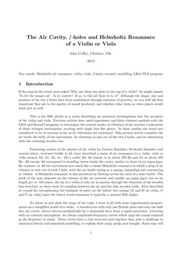
Controlotron’s WideBeam , Cavity-Free Ultrasonic FlowmetersAchieve Process and Natural Gas Custody Transfer Accuracy and PerformanceControlotron’s WideBeam , Cavity-Free ultrasonic flowmeters have been proven tomeet the recently released API standards for liquid custody transfer. This same CavityFree technology is now available for gas applications and will meet AGA-9 standards forcustody transfer.The two major types of ultrasonic flowmeters available for gas custody transfermeasurement are conventional ‘insert’ type meters and Controlotron’s uniqueWideBeam , ‘Cavity-Free’ design.Old School: Typical ‘insert’ ultrasonic flowmeters use sensors that are inserted into themeter body; the signal is transmitted directly between facing transducer pairs with orwithout bounces off the pipe walls. This design results in the inclusion of internalcavities within the meter body. Such wells or cavities can cause maintenance, leakageand pressure containment issues. Cavities in the meter body will also cause eddycurrents in the flow that can cause non-linear performance. The alignment of these‘facing’ sensor pairs is also crucial, requiring expensive castings and milling procedures.The result is a complex geometrical architecture that must remain stable over widetemperature and pressure ranges. Manufacturers employ a variety of multiple path andmultiple ‘bounce’ architectures to achieve acceptable flow profile averaging withcomplex software algorithms.Figure 1Controlotron’s SonicGas Cavity-Free Flowmeter
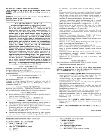
New School: Controlotron’s WideBeam sensors are applied externally to a precision,flanged pipe section; this patented signal injection technology provides a signal that isrefracted into the Gas stream, so as not to require cavities or wells and leaving thestructural integrity of the pipe intact. The resulting meter body is a simple measurementsection; with no flow profile distortion, superior repeatability and stable zero behavior.(See Figure 1) Since the sensors do not intrude into the meter body, there is no specialextraction tool required. In addition:There are no potential leakage pathsThere is no flow profile distortion induced by the sensors or wellsThere is no place for dirt or oil to collect that might cause beam interference.The benefits of this simple measurement meter body with no cavities or wells areobvious. However, the technological challenges of developing this technology weresignificant. A refractive technology, such as Controlotron’s WideBeam design, must:Be capable of adapting to changes in the refraction angle due to gas pressure,temperature and compositionDeliver acceptable rangeability despite beam blowing effects that would tend tomove the signals as flow velocity increases (there are similar issues with inserttype sensors)Have linear performance over a wide range of Reynolds’ numbers despite havinga non-chordal design.These challenges were overcome by utilizing the same WideBeam signal injectiontechnique that has made Controlotron a leader in ultrasonic liquid flow measurement forover 40 years. (See Figure 2.) The WideBeam technique uses transducers that arespecifically matched to the sonic resonance properties of the pipe wall. Controlotronmanufactures specific transducer ranges for each pipe material and wall thickness toproduce a stable, coherent signal within the pipe wall. In effect, the pipe is used as aprecision sounding board and waveguide for the ultrasonic signal.Transmit PulseTransmit Pulse1: Transmit Pulse Enters TransducerTransmit PulsePipewall Signal Detected4: Pipewall Signal EntersReceive TransducerTransmit Pulse2: Sonic Pulse Enters Pipewalland GasTransmit Pulse3: Sonic Pulse Reflects Off Pipewall5: Gas Signal EntersReceive Transducer6: Gas Signal Detected byFlow Display ComputerTransmit PulseFigure 2Note: Signal travels within the pipe wallGas Signal
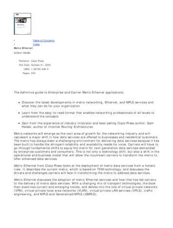
The ‘‘wave guide” action of the pipe wall acts to lengthen the active transmission area ofthe transducer. The effective ultrasonic emitting surface becomes several times thelength of the actual transducer, producing the characteristic wide, phase coherentultrasonic signal in the medium to be measured (gas or liquid). The ‘waveguide’property of the tuned system permits operation over widely changing conditions. Aspressure, temperature and gas composition changes – or as beam blowing occurs withhigher flow velocity - the effective refraction angle of the injected signal changes and thesignal falls at different places on the inside of the pipe. (See Figure 3.) No matter wherethe signal ‘lands’, once it hits the pipe, the waveguide action of the pipe carries thesignal to the receiving transducer with no distortion. The signal processing algorithmsaccurately measure the arrival time and transit-time difference between the upstream /downstream receive signals. These timing measurements determine the flow rate veryaccurately and determine the Sonic Velocity of the Gas to high precision. In fact, theaccuracy of the sonic velocity measurement is testimony to the precision and accuracyof the WideBeam system.This waveguide action is especially important in dealing with beam blowing, as thesignal paths are dramatically different between upstream and downstream. Beamblowing causes the signal sent upstream, against the flow, to take a shorter, steeperpath through the fluid while the downstream path becomes shallower and longer. (SeeFigure 3.) Transit-time correlation can only be performed if each signal travels throughdifferent lengths of pipe wall without distortion. WideBeam signal injection assuresthat the two signals arrive through the pipe wall undistorted.Signal Launch PointsSignal Launch PointsHigh Flow RateFlowHigh Flow RateFlowZero Flow RateDownstream TransmitZero Flow RateUpstream TransmitFigure 3Impact of Beam BlowingSystem uses signal from any launch point, providing accurate flow informationregardless of beam blowing or signal refraction.Without the patented WideBeam pipe matching, refractive systems cannot achievethe stability, accuracy and rangeability over typical application conditions that arerequired for custody transfer applications. Typical inexpensive field clamp-on devicesdo not have this technology and capability.It should be noted that the minimum pressure required for the externally mounted,refractive technique is typically higher than for most insert-type systems. Depending onspecific application conditions; such as type and grade of piping, 10 to 15 bar is typicallyrequired for Custody Transfer performance with WideBeam systems on steel pipe.For plastic pipe and some alternative metal pipes, atmospheric pressure is sufficient.
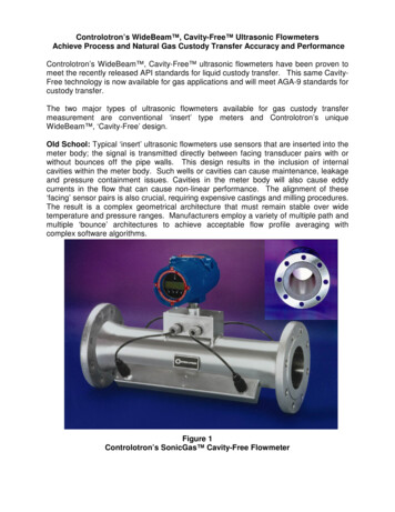
Controlotron WideBeam systems are available in several configurations depending onthe specific application conditions and user requirements. However, the preferredconfiguration is dual-beam, reflect mode. Since the refractive technique must employdiametral path signal injection, the system takes advantage of the ability to reflect thesignal off the far wall. This enables mounting of the transducers on the same side of thepipe, which has additional far-reaching benefits.Upstream TransducerActual angle increasesExpected angleDownstream TransducerCrossflowAxial FlowActual angle decreasesFigure 4Diametric Reflect Mode impact on Crossflow and SwirlThe first, most obvious benefit of diametral operation is direct cancellation of cross-floweffects and minimal impact from swirl. (See Figure 4) However, Controlotron achievesanother benefit from same-side mounting: Zeromatic PathTM – dynamic “zero” underflow conditions. When a transducer sends a signal into the pipe wall, the signal actuallytakes two distinct paths to reach the receiving transducer. The flow measurement pathis the path that the signal takes as it: (Refer to Figure 2 above)1. Refracts into the gas2. Reflects off the far wall3. Falls on the inside surface of the transmitting wall4. Is carried by the waveguide action of the pipe wall to the receiving transducer.However, a second signal actually reaches the receiving transducer first. Since only aportion of the signal injected into the pipe wall enters the gas (due to highly dissimilarsonic impedance factors), the remaining signal is carried by the waveguide properties ofthe pipe wall directly to the receiving transducer through the pipe wall. Because thissignal is not affected by the gas flow, it serves as a constant reference of Zero Flow.Therefore, this ‘Zeromatic Path ’, which is only active in Reflect Mode, eliminates theneed to shut flow in order to set zero and provides a constant zero flow reference thateliminates all potential zero drift that is inherent in ultrasonic systems, since they allhave a ‘live’ zero. Thus, deadband settings can be minimized or eliminated. Thisprovides the potential of the system to be used as a single point leak detector in ablocked line test. Small leaks will be sensed and accumulated over time to show thedirection of leaks through valves or corroded areas.Additional paths provide better flow profile averaging and less error due to asymmetricalprofile conditions. For the majority of Custody Transfer applications, Controlotronrecommends a Dual Beam, Reflect mode system. Large pipes often benefit from aFour-Beam Reflect Mode configuration. For applications that prohibit the use of reflectmode operation (e.g. Large pipes with very high flow velocities), Four-Beam, Direct-X mounting is preferred. Direct-X mounting (See Figure 5) uses two pairs oftransducers each in direct mode mounting, but mounted in opposing directions. Thishas the effect of canceling out crossflow and minimizing the impact of swirl. It should be
noted that the Zeromatic Path feature is not available when mounting in Direct-Xconfigurations, as there is no direct pipe wall path between the transducer paths.Chordal paths must also be specially configured in order to minimize crossflow and swirlerrors. Pairs of paths should be mounted in opposition in order to achieve somecancellation of crossflow. An additional two pairs of transducers should be mounted inopposition, but symmetrically across the pipe in order to provide minimization of errorsdue to swirl. Thus, a single Reflect Mode, Diametric beam has the crossflow andswirl cancellation impact of four chordal paths.Schematic representationIsometric viewFigure 5Direct-X Mounting ConfigurationHow many beams make sense? It depends on the type of system. Insert systemsemploy a very narrow beam of the approximate diameter of the crystals, where onlynatural beam spread insures that the signal will not be “blown” away from the receivetransducer. WideBeam systems take a much larger ‘slice’ of the flow information witheach transmission because it uses the pipe wall as a resonant sounding board, whichgreatly extends the effective emitting and receiving surface of the transducers. EachWideBeam transmission contains a much better representation of average flow thanan insert-type transmission. However, the beams of refractive systems must be acrossthe diameter of the pipe and cannot be arranged as chordal geometries.Chordal-based designs offered a theoretical advantage in that they are thought to beReynolds’ Number insensitive. However, in part due to local flow profile disturbancesnear the cavities and the inherent limited information acquired by each transmission ofthe ‘narrow’ beam, these theoretical benefits begin to pale when compared to theoverall benefits offered by the WideBeam , Cavity-Free design. In addition, recentdata suggest that Reynolds’ numbers does have an influence on the performance ofchordal systems. WideBeam designs include Reynolds’ Number compensation andwhen applied, offer equal or better linearity and rangeability than insert chordal systems.In addition, chordal type designs typically must employ up to four times as many pathsin order to provide opposing / symmetric transducer pairs for cross-flow and swirlcancellation – a feature of a single pair of WideBeam transducers mounted in reflectmode. It should be noted that manufacturers generally suggest avoiding the use of themeters within the Transition Region from Laminar to Turbulent flow – despite chordaldesigns.Controlotron’s WideBeam, Field Installed Check Meters have been used successfullyand tested at several customer facilities and testing labs. (See Figures 6, 7, and 8.)
Flow Testing of Controlotron’s 1010GCDN Dual Beam Clamp-OnGas Meter on 12” Pipe Line – As found, Out of the Box Data vs.Instromet Five Beam Insert Spool System (6/18/02 Test Date)2.0%1.5%Difference (% ) (uncalibrated)1.0%Out of the Box - No 60Flow Velocity (ft/sec)Dual Beam Reflect Mount Installation at Ysclosky LA, USA(Line Pressure: 58 barg)7014201415Velocity Path 1Velocity Path 2VOS Path 1(fps)VOS Path 2 .35.001385*&#'## ,(-).*1'1')/(Figure 6Test Setup and Results, System 1010GC vs. Insert Ultrasonic MeterSingle Beam System 1010GC vs. Calibrated Turbine20" Pipe with 30D straight Upstream length2.01.5"Out-of-theBox,"uncalibrated test %0Time (from 6/18/02)Deviation (% )11.25.0010!"!# %Gas Sound velocity (ft/sec)Controlotron Data5011.15.00Flow Velocity (ft/sec)607,0009,00011,0003Flowrate (m /h), for rates qtFigure 7Test Results, System 1010GC vs. Turbine Flowmeter13,000
Results of Testing Field Clamp-On System 1010GCvs. Turbine Reference Meter (8CS40 Pipe)2.00Deviation (%)(FWME Correction per AGA-9)1.501.000.500.00-0.50130 f/s, w/o FlowConditioner and nocorrection, 02,5003,0003,5004,0004,5003Flow (m /hr) (Flow Rates qt)Figure 8Results of Testing at TCCFigure 8 shows the results of testing a field-installed Controlotron System 1010GC vs. aturbine meter. The uncalibrated plot shows the actual, uncorrected results. The“calibrated” plot shows a linear calibration around zero. From this plot it can be seenthat the 1010GC results are within 0.2%, well within AGA-9 requirements.ConclusionControlotron’s WideBeam, Cavity-Free Ultrasonic flowmeters provide benefits in totalcost of ownership, maintainability, and reliability while providing equal or betterperformance than conventional (Old School) insertion type ultrasonic flowmeters.External Transducer Mounting Advantages1. External Mounting is cavity-free, with no chance of dirt or oil build up,condensation, pooling, and corrosion – all of which can block the sonic beam andimpact linearity and accuracy.2. External mounting requires no special extraction tool for transducer replacementor inspection. Transducer installation, inspection, and service can be done easilyand at full pipeline pressure.3. External Mounting provides no additional potential leak paths.4. External mounting results in a simple meter body geometry, which is temperaturestable, and has no complex transducer alignment issues. This should translateto lower price and lower maintenance costs.5. External mounting enables field-clamp-on products to provide simple fieldinstallation without cutting pipe or stopping flow.
6. External mounting, in Reflect Mode offers better zero stability by employing acontinuously active Zeromatic Path.7. Externally mounted transducers operate at significantly higher frequencies thaninsert transducers. This makes them highly immune to environmental noise thathas been a source of problems for insert sensors.8. External Mounting requires fewer paths than chordal techniques as cross-flow iscancelled out in each path (in reflect or same-side mounting), and the diametricconfiguration is highly tolerant of swirl conditions. In addition, using a reflectmode configuration, the path-length is typically more than twice as long as atypical chordal path and, due to WideBeam transmission, represents a muchwider sample of flow.
The two major types of ultrasonic flowmeters available for gas custody transfer measurement are conventional ‘insert’ type meters and Controlotron’s unique WideBeam , ‘Cavity-Free’ design. Old School: Typical ‘insert’ ultrasonic flowmeters use sensors that are inserted into the