Transcription
www.aqcinspection .comUltrasonic testing HandbookSUBJECT: Guide for Ultrasonic testingAUTHOR: Vigneshwaran chandrasekaranCOYRIGHT: Advanced Qauality CentreThe document is a copyright of advanced quality centre, Coimbatore, india,reprinting or republishing the document without a written consent isprohibitedDate of publish: 25.04.2020www.aqcinspection.com
www.aqcinspection .comScope of document:The document is a hand book for Non Destructive Testing Engineers to perform Ultrasonic Testing ,explains the applicable type of defects, basics of Ultrasonic Testing, Applicable Standards andAcceptance criteria for Ultrasonic TestingIntroduction to NDTIndustries manufacture their components based on the codes mentioned in the international standards, To selltheir product in the global market, such products with globally accepted standards will satisfy the clientsrequirement and will be safe to use, today’s competitive market also involves such standards to produce highquality products under reduced cost of control.The application of Non Destructive Examination will reduce the cost of rejection after processing such asmachining, fabrication, heat treatment, coating and transportation.Types of DefectsThe defects can occur in three different periods – during casting (I. Inherent Defects), during Processing (II.processing defects) & in working condition (III. service defects)I. Inherent defectsThe below mentioned are possible defects that are formed when poured molten metal solidifies to form acomponent.Typical inherent discontinuities found in the castings are Cold Shuts, Hot Tears, Shrinkage Cavities,Micro Shrinkage, Blow Holes and Porosities.A Cold Shut is caused when molten metal is poured over solidified metal as shown below:
www.aqcinspection .comHot Tears (Shrinkage Cracks) occur when there is unequal shrinkage between light and heavy sectionsas shown below:Shrinkage Cavities are usually caused by lack of enough molten metal to fill the space created byshrinkage, similar to pipe in the ingot.Micro Shrinkage is usually many small sub surface holes that appear at the gate of the casting.
www.aqcinspection .comMicro Shrinkage can also occur when the molten metal must flow from a thin section into a thickersection of a casting.Blow Holes are small holes at the surface of the casting caused by gas which comes from the moulditself, many molds are made of sand, when molten metal comes into contact with the mold, the waterin the sand is released as steam,Porosity is caused by entrapped gas; porosity is usually subsurface but can occur on the surfacedepending on the design of the mold.II.Processing DefectsProcessing discontinuities are those found or produced by the forming or fabrication operationsincluding rolling, forming, welding, machining, grinding and heat treating,As a billet is flattened and spread out nonmetallic inclusions may cause a lamination, Pipe and Porositycould also cause laminations in the same manner as shown below:As a billet is rolled into bar stock, nonmetallic inclusions are squeezed out into longer and thinnerdiscontinuities called stringers.
www.aqcinspection .comWelding DefectsThere is possibility of discontinuities in other words called as “Defects” formed during the process of welding orduring cooling for solidification. The causes for the defects are various few of them are described below.Before understanding the defects we will refresh the nomenclature of the weld which is shown in the belowfigure:
www.aqcinspection .com1) Undercut – at the weld fusion area/ weld toe on the base metal, may occur on the face side or rootside of the weld.Cause :- Caused due to excessive heat melting the base metal probably caused by two reasons. Theyare Slowdown of welding speed at that particular location or increase in the current suddenly withconstant speed.2) Underfill – Occur at face side of the weld, can be identified as lower surface level than the adjacentbase metal.Cause: Pour of less or insufficient weld metal during welding required more filling.3) Excess Penetration- Occurs at root of the weld, can be identified as excess weld drop at root.Cause:- Occurs due to excessive root Gap , less root face and excess current during these conditions.Avoid too much root gap and provide adequate root face to support the high heat input during weld.4) Lack of Penetration : Occurs at the root side of the weld can be identified as lack of weld metal at theroot side and both the root face edges will be visible as shown below.
www.aqcinspection .comCause :- May be due to any of the following reasons- Less Root Gap, More root face, too small bevelangle, Less current, Too large electrode diameter, Longer arc length.5) Incomplete fusion: Occurs as gap between the weld metal and base metal and can be at any location,Root, Face or at Sidewall.Cause:- Due to improper welding skill, incorrect welding current and voltage, incorrect travel speed,poor inter run cleaning & wrong selection of electrode.6) Root Concavity: Can be observed as suck back or concave like depression in the root, even thoughboth the root faces has fused with weld metal.Causes:- Insufficient arc power to produce positive bead, excessive backing pressure ( if purging isdone), Lack of welder skills, Slag flooding in backing bar groove.7) Excess weld Reinforcement: Occurs in the face side of the weld as improper weld bead as shownbelow. It is considered as defect because of formation of sharp corners at toes.8) Misalignment: Found as un even level(up and down ) between two joining base metal.
www.aqcinspection .comCause: may be caused during pre-welding fit-up, or after welding due to in adequate tack welds andtemporary retainers.9) Cracks: Cracks may be found as longitudinal or transverse, and also may be found in the base metalnear to weld (HAZ Heat Affected Zone) as shown in the figure. Hot cracks occur during welding andcooling or during heat treatment process. Cold cracks occurs during the service due to loadsCauses: May be due to any or all of the following reasons. Improper electrode, Improper cooling rate orquenching, High carbon content steel, High Sulphur and phosphor content in steel . Certain alloys, weldingon coated steels, Cold cracking mostly starts from HAZ areas due to internal & external stress, and hydrogeninduced.10) Porosity: Occurs as round or curved cavities in the weld, may be single, clustered or aligned.Cause:- Due to absorption of nitrogen, oxygen and hydrogen in the molten weld metal . The gases areinvolved in the weld metal due to moisture in base metal or welding electrodes, and poor gas shielding.11) Spatter : Weld metal splashed and sticks to the surface of the weld or base metal. Few are easilyremovable and few has to be grinded down.
www.aqcinspection .comCauses: Long welding arc., Short welding arc, Cleanliness of the base material surface. Selection ofgas welding (CO2 welding yields more), Welding at a wrong angle.Imbalance between voltage and amperage, incorrect wire feed speed.12) Arc Strike: Occurs as a base metal damage and splash of melted base metal on the base metal surface.Causes: When Electrode holder touches the other base metal areas causing an arc between the base metaland the holder.13) Slag Inclusions: Occurs as non-metallic left outs in the weld metal or between the weld metal andbase metal as shown below. These slag inclusions causes lack of fusion at few locationsCauses: The flux layer formed over the solidified weld pool if not cleared forms as slag inclusion. Themelted holders in MIG welding form Copper inclusions on the weld metal. The melted tungsten rod inTIG welding forms Tungsten inclusions on the base metal.14) Crater / Crater Pipe / Crater Cracks: Craters occurs as elliptical shaped depression at end of weld orweld stopping point. Crater pipe occurs as a hole at the center of crater and crater crack occurs as starshaped crack at the middle of the crater.
www.aqcinspection .comCauses: Crater is caused due to improper weld stopping technique, crater pipe or crack is formed due tolow weld filling at the crater area. Crack is formed during cooling due to insufficient metal.15) Overlap: Occurs as Weld metal flown more than the edge of the face as shown below.Causes: Overlap is caused due to wrong electrode angle, slow welding speed, high current andcontamination.III. Service DiscontinuityService discontinuities occur when the finished product is exposed to the workingenvironment which involves exposure of External stress, corrosive environment,chemical attack and much more.Probable service defects are Cold Cracks, Pitting, deformation, brittleness andbreaking.Ultrasonic Testing – UTUltrasonic Testing Utilises Sound waves with frequencies more than 20,000Hz to travel into thematerial to be inspected and finds out Defects or makes measurements,Basic principle:
www.aqcinspection .comAny defect or measurement is made by the fact that sound continues to travel in a material until itmeets a interference zone of material having different acoustic characteristics (impedance), thereis a reflection of few percentage of sound waves (% of reflection depends upon latitude ofdifference in acoustic impendence )WAVE PROPAGATION:Ultrasonic testing is based on the vibration in materials which is generally referred to asacoustics. All material substances are comprised of atoms, which may be forced intovibrational motion about their equilibrium positions. Many different patterns of vibrationalmotion with at the atomic level; however, most are irrelevant to acoustics and ultrasonictesting. Acoustics is focused on particles that contain many atoms that move in harmony toproduce a mechanical wave. When a material is not stressed in tension or compressionbeyond its elastic limit, its individual particles perform their elastic oscillations. When theparticles of a medium are displaced from their equilibrium position, internal restoration forcesarise. These elastic restoring between particles lead to the oscillatory motions of the medium. Insolids, sound waves can propagate in four principal modes that are based on the way theparticles oscillate. Sound can propagate as longitudinal waves, shear waves surface waves andin thin materials as plate waves longitudinal and shear waves are the two modes of propagationused in the ultrasonic testing as shown in the figureSnell’s law:It describes the relationship between the angles and thevelocities of the waves. Snell’s law equates the ratio ofmaterial velocities to the ratio of the sine’s of incident andrefracted angles, as shown in the following equation
www.aqcinspection .comTransducers:There are two types of transduceri.ii.Contact type transducerImmersion transducerPiezoelectric transducer (contact type)The conversion of electrical pulses to mechanical vibrations and conversion of returnedmechanical vibration into electrical energy is the basis of UT .The conversion is done by thetransducer using piezoelectric material with electrodes attached to the two of the oppositefaces .When an electric field is applied across the material, the molecules will alignthemselves with the electrical field causing the material to change dimensions. In addition, apermanently polarized material such as quartz and barium titanate will produce an electricfield the material will change dimensions as a result of imposed mechanical force. Thephenomenon is known as piezoelectric effect
www.aqcinspection .comCharacteristics of piezoelectric transducer :The function of transducer is toconvert electrical signal intomechanical vibration and vice versaA cut away of typical contacttransducer is shown in the fig. To getas much as energy out of thetransducer .Optimal impedancematching is achieved by sizing thematching layer so that the thickness is ¼ of the desired wavelength. This keeps the waves thatare reflected within the matching layer in the phase when the exit the layer, for this type oftransducer is made up of material which has acoustic impedance similar to that of the activeelement and steel, it also has wear plate to protect the matching layer and active element fromscratchingThe backing material has greater influence on the damping characteristics of a transducer. Asthe mismatch in the impedance between the active element and the backing materialincreases, material penetration increases but transducer sensitivity is reduced. The bandwidthrefers to the range of frequencies associated with the transducer. The frequency noted on thetransducer s the central frequency and depends primarily on the backing material. The centralfrequency will also define the capabilities of the transducerImmersion type:These transducers are designed to operate in the liquid environment and all the connectionsare water tight. Immersion transducers usually have an impedance matching layer helps to getmore sound energy into water and in into components being inspected. Immersiontransducers can be purchased with a planer focused or spherically focused lens. A focusedtransducer can improve the sensitivity and axial resolution by concentrating the sound energyto a smaller area. It is used inside a water tank or as part of a squitter or bubbler system inscanning application
www.aqcinspection .comUltrasonic Testing Techniques:There are three types of techniques which are mainly used during inspectioni.ii.A-scan technique:It displays the amount of received ultrasonic energy as a function of time. The relativeamount of received energy is plotted along the vertical axis and the elapsed time isdisplayed along the horizontal axis. Most instruments with a an A-scan display allowthe signal to be displayed allow the signal to be displayed in its natural radiofrequency form, as a fully rectified RF signal, or as either the positive or negative halfof the RF signal, or as the positive or negative half of the RF signal. In the A-scanpresentation, relative discontinuity size can be estimated by comparing the signalamplitude obtained from unknown reflector. Reflector depth can be determined by thesignal on the horizontal time axisB-scan technique:The B-scan presentation is a type of presentation that is possible for automated linearscanning systems where it shows a profile of the test specimen. In the B-scan, the timeof flight of the sound waves is displayed along the vertical axis and the linear position ofthe transducer is displayed along the horizontal axis. From the B-scan, the depth of thereflector and its approximate linear dimensions in the scan direction can be determined.The B-scan is typically produced by establishing a trigger gate on the A-scan. Wheneverthe signal intensity is great enough to trigger the gate, appoint is produced on the Bscan. The gate is triggered by the sound reflected from the back wall of the specimenand by smaller reflector within the material. In the B-scan image shown previously, lineA is produced as the transducer moves to the right of this section, the back wall line BWis product. When the transducer is over flaws B and C, lines that are similar to thelength of flaws and at similar depth of the material are drawn on the B-scan .It should benoted that limitation to this display technique is that reflectors may be masked by largereflector near surface
www.aqcinspection .comiii.C-scan technique:The C-scan presentation is a type of presentation that ispossible for automated for two-dimensional scanning systemsthat provides a plan type view of the location and size of testspecimen features. The plane of the image is parallel to thescan pattern of the transducer. C-scan presentations aretypically produced with an automated data acquisition system,such as computer controlled scanning system. Typically, adata collection gate is established on the A-scan and theamplitude or the time-of-flight of the signal is recorded atregular intervals as the transducer is scanned over the test piece. The relative signalamplitude or the time-of-flight is displayed as a shade of grey or a color for each of thepositions where data was recorded. The C-scan presentation provides an image of thefeatures that reflect and scatter the sound within and on the surfaces of the test pieceHigh resolution scans can produce very detailed images.The figure shows two ultrasonic C-scan images of a US quarter.Both images were produced using a pulse-echo technique with thetransducer scanned over the head side in an immersion scanningsystem. For the C-scan image on the top/ the gate was set to capturethe amplitude of the sound reflecting from the front surface of thequarter. Light areas in the image indicate areas that reflected agreater amount of energy back to the transducer. In the C-scanimage on the bottom, the gate was moved to record the intensity ofthe sound reflecting from back surface of the coin. The details onback surface are clearly visible since the sound energy is affectedby these features as it travels through the front surface of the coinCalibration method:Calibration refers to the act of evaluating and adjusting the precision and accuracy ofmeasurement equipment. In UT, several forms of calibrations must occur. First, theelectronics of the equipment must be calibrated to ensure that they are performing asdesigned. In UT reference standards are achieved a general level of consistency inmeasurements and to help interpret and quantify the information contained in the receivesignal. The fig shows some of the commonly used to validate that the equipment and thesetup provide similar results from one day to the next and that similar results areproduced by different systemsReference standards are mainly used for Checking the performance of both angle beam and normal beam transducers Determining the sound beam exit point of angle beam transducers Determining the refracted angle produced Evaluating instrument performance
www.aqcinspection .comSome of the common standards usedIIW Type US-1 Calibration BlockThis block is a general purpose calibration block that can be used for calibrating angle;beam transducers as well as normal beam transducers. The material from which IIW blocksare prepared is specified as killed, open hearth or electric furnace, low carbon steel in thenormalized condition and with a grain size of McQuaid-Ehn No.8. Official IIW blocks aredimensioned in the metric system of units. The block has several features that facilitatechecking and calibrating many of the parameters and functions of the transducer as well asthe instrument where that includes; angle beam exit, beam angle, beam speed spared, timebase, linearity, resolution, dead zone, sensitivity and range setting.TASTM-Miniature Angle-Beam Calibration Block (V2)The miniature angle-beam block is used in a somewhat similar manner as the IIW block,but is smaller and lighter. The miniature angle-beam block is primarily used in the fieldfor checking the characteristics of angle-beam transducers.With the miniature block, beam angle and exit point can be checked for an angle-beamtransducer. Both the 25 and 50 mm radius surfaces provide ways for checking thelocation of the exit point of the transducer for calibrating the time base of the instrumentin terms of the metal distance. The small hole provides a reflector for checking beamangle and for setting the instrument gain.Inspection Technique:i.Normal Beam InspectionPulse-echo ultrasonic measurements can determine location of a discontinuity in apart of a structure by accurately measuring the time required for short ultrasonicpulse generated by a transducer to travel through a thickness of a material reflect
www.aqcinspection .comfrom the back of a surface of a discontinuity and be returned tothe transducer. In most applications, this time interval is a fewmicroseconds or less. The two way transit time measured isdivided by two to account down-and-back travel path andmultiplied by the velocity of sound in the test material. Theresult is expressed in the well-known relationshipWhere d is the distance from the distance to the discontinuity in the test piece, Vis the velocity of sound waves in the material, and t is the measured round-triptransit time.Precision ultrasonic thickness gages usually operate at frequencies between 500kHz and 100 MHz, by means of piezoelectric transducers that generate bursts ofsound waves when excited by electrical pulses. Typically, lower frequencies areused to optimize penetration when measuring thick, highly attenuating, nonscattering materials. It is possible to measure most engineering materialsultrasonically, including metals, plastic, ceramics, composites, epoxies, and glassas well as liquid level and the thickness of certain biological specimens. On-lineor in-process measurement of extruded plastics or rolled metal often is possible, asis measurements of single layers or coatings in multilayer materials.ii.Angle Beam InspectionAngle beam transducers and wedges are typically used to introduce a refractedshear wave into the test material. An angled sound path allows the sound beam tocome in from the side, thereby improving detectability of flaws in and aroundwelded areas. Angle beam inspection is somehow different than normal beaminspection. In normal beam inspection, the back wall echo is always present on thescope display and when the transducer basses over a discontinuity a new echo willappear between the initial pulse and the back wall echo. However, when scanninga surface using an angle beam transducer there will be no reflected echo on thescope display unless a properly oriented discontinuity or reflector comes into thebeam path. If a reflection occurs before the sound waves reach the back wall, thereflection is usually referred to as “first leg reflection”. The angular distance
(Sound Path) to the reflector can be calculated using the same formulaused for normal beam transducers (but of course using the shear velocityinstead of the longitudinal velocity) as:If a reflector came across the sound beam after it has reached and reflectedoff the back all, the reflection is usually referred to as “second legreflection”. In this case, the “Sound Path” (the total sound path for the twolegs) and the “Surface Distance” can be calculated using the same equationsgiven above; however the “Depth” of the reflector will be calculated asImportant Formulae for Ultrasonic Testing:1) Frequency of Probe: F V/ λbe found), Where ( λ 2 x Minimum Size of Defect toV- Velocity of sound in material under considerationλ- Wavelength,2) Near Zone of Normal Probe: N D² / 4 λ, Where ( λ V / F)(D – Diameter of probe,
λ- Wavelength,V- Velocity of sound in material under considerationF- Frequency of Probe3) Near Zone of Angle Probe: N l - Length of the piezo electric elementb – Breath of the piezo electric elementλ – Wavelength of the sound , λ V / F4) Beam Spread Angle θ: sin (ϴ/2) 1.22 (ʎ/D)λ – Wavelength of the sound , λ V / FD – Diameter of the probe element5) Probe Angle Selection : θ 90 - Thickness of the Weld Plate6) Skip Distance: ½ Skip T x Tan θ, 1 Skip 2 ( T x Tan θ), 1 ½ Skip 3 (T xTan θ) T – Thickness of the test plateθ - Probe angle7) Beam Path : 1st Leg T / Cos θ, 2nd leg 2 (T / Cos θ), 3rd Leg 3 (T / Cos θ)Few of the important Sound Velocity in the materials are given below:
MaterialLongitudinal VelocityShear VelocityImpedanceAir330 m/s---0.003Water1400 m/s---1.49Steel5890 to 5940 m/s3255 m/s45.1Quartz5740 m/s2760 m/s30Oil1800 m/s--1.5Aluminium6300 m/s3800 m/s4Plastic2700 m/s2200 m/sNear Zone and Beam Spread for different Probes are given below for referenceProbeNθ/2Ø10mm, 2 MHz8.12521.16Ø10mm, 4 MHz1610.42Ø10mm, 6 MHz256.64Ø24mm, 2 MHz48.67.24Ø24mm, 4 MHz97.294.37Ø24mm, 6 MHz146.602.7628x9 , 2 MHz1.019.478x9 , 4 MHz2.034.72112x12, 2 MHz1.446.70812x12, 4 MHz2.88663.34
20x20, 2 MHz4.5743.823Inspection Standards:ASME BPVC Section V, Article 4 – Ultrasonic Examination of WeldsASME BPVC Section V, Article 5 – Ultrasonic Examination of MaterialsASME BPVC Section V, Article 23 – Ultrasonic StandardsSA-388/SA-388M Standard Practice for Ultrasonic Examination of Steel ForgingsSA-435/SA-435M Standard Specification for Straight-Beam Ultrasonic Examination of Steel PlatesSA-577/SA-577M Standard Specification for Ultrasonic Angle-Beam Examination of Steel PlateSA-578/SA-578M Standard Specification for Straight-Beam Ultrasonic Examination of Rolled Steel Platesfor SpecialApplicationsSA-609/SA-609M Standard Practice for Castings, Carbon, Low-Alloy and Martensitic Stainless Steel,Ultrasonic Examination ThereofSA-745/SA-745M Standard Practice for Ultrasonic Examination of Austenitic Steel ForgingsSB-548 Standard Test Method for Ultrasonic Inspection of Aluminum-Alloy Plate for Pressure VesselsSD-7091 Standard for measurement of painting thickness using UT methodSE-213 Standard Practice for Ultrasonic Testing of Metal Pipe and TubingSE-273 Standard Practice for Ultrasonic Testing of the Weld Zone of Welded Pipe and TubingSE-317 Standard Practice for Evaluating Performance Characteristics of Ultrasonic Pulse-Echo TestingInstruments and Systems Without the Use of Electronic Measurement InstrumentsMethodSE-797/SE-797M Standard Practice for Measuring Thickness by Manual Ultrasonic Pulse-Echo ContactSE-2491 Standard Guide for Evaluating Performance Characteristics of Phased-Array Ultrasonic TestingInstruments and Systems
SE-2700 Standard Practice for Contact Ultrasonic Testing of Welds Using Phased ArraysISO 17640 – Non Destructive Testing of Welds – Ultrasonic Testing – Techniques, Testing Levelsan assessmentISO 16831 Non-destructive testing — Ultrasonic testing — Characterization and verification of ultrasonicthickness measuring equipmentISO 4992 – Non Destructive Testing of Steel Castings (with ferritic structure for generalpurpose)SAE AMS 2630 B – Aerospace Standard for Ultrasonic Testing of Material over 12.7mm ThicknessSAE AMS 2632 – Aerospace Standard for Ultrasonic Testing of Material less than 12.7mmThicknessAWS D1.1 Part F 6.20 – Ultrasonic Testing Procedure for Structural Steel WeldsASTM E 164 – Standard Practice for Ultrasonic Contact Examination of WeldmentsASTM E 127 & 428 – Standard for machining of UT Reference blocks
Acceptance Criteria :ASME Section VIII Division 1 - Pressure Vessel Construction – Ultrasonic TestingThese Standards shall apply unless other standards are specified for specific applications within thisDivision.Imperfections which produce a response greater than 20% of the reference level shall be investigated tothe extent that the operator can determine the shape, identity, and location of all such imperfectionsand evaluate them in terms of the acceptance standards given in (a) and (b) below.(a) Indications characterized as cracks, lack of fusion, or incomplete penetration is unacceptableregardless of length.(b) Other imperfections are unacceptable if the indications exceed the reference level amplitude andhave lengths which exceed:(1) 1/4 in. (6 mm) for t up to 3/4 in. (19 mm);(2) 1/3t for t from 3/4 in. to 21/4 in. (19 mm to 57 mm);(3) 3/4 in. (19 mm) for t over 21/4 in. (57 mm).where t is the thickness of the weld excluding any allowable reinforcement. For a butt weld joining twomembers having different thicknesses at the weld, t is the thinner of these two thicknesses. If a fullpenetration weld includes a fillet weld, the thickness of the throat of the fillet shall be included in t .ASME B 16.34 - Valves - Ultrasonic TestingAcceptance Standards.Straight Beam ExaminationIndications which are equal to or exceed that obtained from a 6.4 mm (0.25 in.) diameter flatbottomed hole in a calibration test piece of thickness equal to the defect depth areunacceptable.Angle Beam ExaminationIndications which are equal to or exceed those obtained from a 60 deg V-notch, 25 mm (1.0 in.)long and having a depth not greater than 5% of the nominal wall thickness in a test piece areunacceptable.
ASME B 31.1 – Power Piping – Ultrasonic TestingAcceptance Standards. Welds that are shown by ultrasonic examination to have discontinuitiesthat produce an indication greater than 20% of the reference level shall be investigated to theextent that ultrasonic examination personnel can determine their shape, identity, and locationso that they may evaluate each discontinuity for acceptance in accordance with (B.1) and (B.2)below.(B.1) Discontinuities evaluated as being cracks, lack of fusion,. or incomplete penetration areunacceptable regardless of length.(B.2) Other discontinuities are unacceptable if the indication exceeds the reference level andtheir length exceeds the following:(B.2.1) ¼” (6.0 mm) for t up to ¾” (19.0 mm).(B.2.2) 1/3 t for t from ¾” (19.0 mm) to 2 ¼ “ (57.0 mm).(B.2.3) ¾”. (19.0 mm) for t over 2¼” (57.0 mm)Where t is the thickness of the weld being examined. If the weld joins two members havingdifferent thicknesses at the weld, t is the thinner of these two thicknesses.ASME B31.3 Process Piping – Ultrasonic TestingInspection of Weld Joints carried as per ASME Section V , Article 4Pipe and Tubing(a) Method. Pipe and tubing, required or selected in accordance with Table K305.1.2 to undergoultrasonic examination, shall pass a 100% examination for longitudinal defects in accordancewith ASTM E213, Ultrasonic Testing of Metal Pipe and Tubing. Longitudinal (axial) referencenotches shall be introduced on the outer and inner surfaces of the calibration (reference)standard in accordance with Fig. 3(c) of ASTM E213 to a depth not greater than the larger of 0.1mm (0.004 in.) or 4% of specimen thickness and a length not more than 10 times the notchdepth.(b) Acceptance Criteria. Any indication greater than that produced by the calibration notchrepresentation
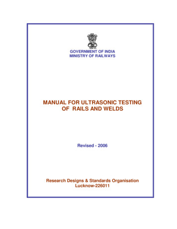
AWS D 1.1 Structural Steel Welding – Ultrasonic Testing Acceptance Criteria :For Statically loaded Non Tubular Connections:-
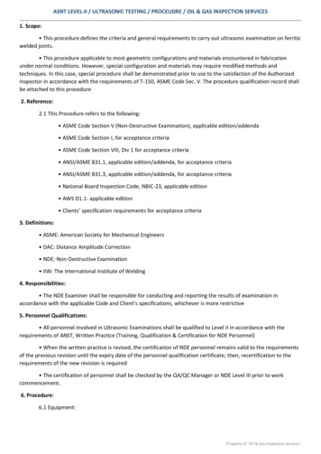
For Cyclically loaded Non Tubular Connections:-
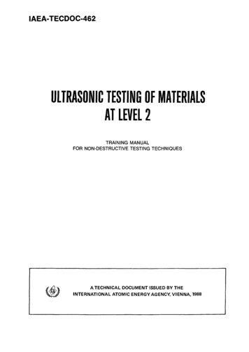
How to Interpret AWS D1.1 UT Acceptance CriteriaYour
Ultrasonic testing Handbook SUBJECT: Guide for Ultrasonic testing AUTHOR: Vigneshwaran chandrasekaran COYRIGHT: Advanced Qauality Centre The document is a copyright of advanced quality centre, Coimbatore, india, reprinting or republishing the document without a written consent is prohibited Date of publish: 25.04.20