Transcription
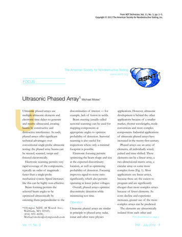
SSC-21 3.h,. .:.,, ,. . :.Z. A GUIDE FOR ULTRASONICEVALUATIONTESTINGOF WELDThis document has been approvedfor public release and sale; itsdistributionis unlimited.iSHIP STRUCTURE COMMITTEEI 970FLAWSAND
SHIP STRUCTURE IPCOASTsys TTEEGUARDD.C.HEADQUARTERS20591SHIPPING1970Dear Sir:10 maintain the high degree of safety and reliability in ship fabrication, the Ship Structure Committeehas completed a project that provides an ultrasonic inspection quide that retain the comparable radiographic standardprovided earlier.The resultsofthis projectare contained inthis report,Rear Admiral, U,S. Coast GuardChairman, Ship Structure Committee:!i,—-,
SSC-213Final ReportonProject SR-188,, ‘[Ultrasonic Test Guide”to theShip Structure CommitteeA GUIDE FOR ULTRASONIC TESTING AND EVALUATIONOF MELD FLAWSbyR. A. YoushawU.S. Naval Ordnance LaboratoryunderDepartment of the NavyNaval Ship Engineering CenterProject No. SF 35422306Task 02022This document haz been approved foY publicrelease and sale; itsdist ibution is unlimited.U. S. Coast Guard HeadquartersWashington, D.C.1970
ABSTRACTThis document presents procedures and acceptance limitsinspection of steel butt welds in thefor contact ultrasonicThe acceptance limits dethickness range of 1/4 to 2 inches.scribed in the following sections are compatible with those setNondestructiveforth in SSC-177,“Guide for Interpretation ofTests of Welds in Ship Hull Structures” for radiographic inspection and should therefore result in satisfactory ship welds.ii
SHIP STRUCTURE COMMITTEEThe SHIP STRUCTURE COMMITTEE is constituted to prosecute a researchof knowledgeprogram to improve the hull structures of ships by an extensionpertaining to design, materials and methods of fabrication.RADM W. F. Rea, 111, USCG, ChairmanChief, Office of Merchant Marine SafetyU. S. Coast Guard HeadquartersMr. E. S. DillonDeputy ChiefOffice of Ship ConstructionMaritime AdministrationCapt. Id.R. Riblett, USNHead, Ship Engineering DivisionNaval Ship Engineering CenterCapt. T. J. Banvard, USNMaintenance and Repair OfficerMilitary Sealift CommandMr. C. J. L. choefer, Vice PresidentAmerican Bureau of ShippingSHIP STRUCTURE SUBCOMMITTEEThe SHIP STRUCTURE SUBCOMMITTEE acts for the Ship Structure Committeeon technical matters by providing technical coordination for the determinationof goals and objectives of the program, and by evaluating and interpreting theresults in terms of ship structural design, construction and operation.NAVAL SHIP ENGINEERING CENTERU. S. COAST GUARDMr.Mr.Mr.Mr.Mr.LCDR C. S. Loosmore, USCG - SecretaryCDR C. R. Thom son. USCG - MemberLCDR J. W. Kime, U CG - AlternateCapt. L. A. Colucciello, USCG - Alternat J.J.G.H.I.B. O’Brien - Acting ChairmanB. O’Brien - Contract AdministratorSorkin - MemberS. Sayre - AlternateFioriti - AlternateNATIONAL ACADEMY OF SCIENCESMARITIME ADMINISTRATIONMr.Mr.Mr.Mr.F.A.R.W.Dashnaw - MemberMaillar - MemberFalls - AlternateG. Frederick - AlternateMr. A. R. Lytle, LiaisonMr. R. W. Rumke, LiaisonProf. R. A. Yagle, LiaisonSOCIETYOFAMERICAN BUREAU OF SHIPPINGNAVAL ARCHITECTS & MARINEENGINEERSMr. S. G. Stiansen - MemberMr. F. J. Crum - MemberNr. T. H. Buermann, LiaisonOFFICE OF NAVAL RESEARCHAMERICAN IRON AND STEEL INSTITUTEMr. J. M. Crowley - MemberDr. W, G. Rauch - AlternateMr. J. R. LeCron, LiaisonNAVAL SHIP RESEARCH & DEVELOPMENT CENTERBRITISH NAVY STAFFMr. A. B. Stavovy - AlternateDr. V. Flint, LiaisonCDR P. H. H. Ablett, RCNC, LiaisonMILITARY 5EALIFT COMMANDWELDING RESEARCH COUNCILMr. R. R. Askren - MemberLt. J. G. T. E. I oster,USN, - MemberMr. K. H. Koopimn, LiaisonMr. C. Larson, Liaisoniii
CONTENTSSCOPE. . . . . . . . . . . . . . . . .1TEST METHOD . . . . . . . . . . . . . .1PERSONNEL QUALIFICATION. . . . . . .3CALIBRATION STANDARDS. . . . . . . .4INSTRUMENT CALIBRATION. . . . . . . .4WELD INSPECTION. . . . . . . . . . . .5DISCONTINUITY LENGTH DETERMINATIONS. . . . . . . . .5DISCONTINUITY EVALUATION . . . . . . .8RECORD OF INSPECTION . . . . . . . . . . . . . . . . .8GLOSSARY OF TERMS. . . . . . . . . . . . . . . . . . 11iv—.
SCOPEThis document presents procedures and acceptance limitsfOr COntact ultrasonic inspect nof steel butt welds in thethickness range of 1/4 to 2 inches. The acceptance limitsdescribed in the following sections are compatible withthose set forth in SSC-177,“Guide for Interpretation ofNondestructive Tests of Welds in Ship HU1l Structures” forradiographic inspection and should therefore result in satisfactory ship welds. Occasions may arise where radiographicinspection could provide additional information.TEST METHODGeneral - The procedures given apply to the contactultrasonic inspection of butt welds. Weld inspection isaccomplished by introducingshear waves into a Plate at aselected angle and manipulating the transducer so as to scanthe entire weld Fig. A-l.\,/’-FIG. A-1.TECHNIQUE FOR INSPEC”rIiiGBIJT’ildELESMITH SHEAR WAVESEuuiPment - The ultrasonic instrument shall be of EheIt shall bepulse-echo type with an A-scan presentation.receivinganddisplayingscreen pulsescapable of generating Theinstrumentshallfrom 1 to 5 MHz on the cathode ray tube.have a circuitry to provide a continuously increasing amplification with respect to time or distance of travel. Acalibrated decibel attenuator control is recommended. Battery-.—
-2-powered equipment must contain an alarm to signal batterydepletion prior to instrument shut-off due to battery exhaustion.Transducers - The maximum dimension (manufacturers’specifications) of the transducer active element shall notexceed one inch. A ratio of 2:1 width to height of the activeelement is recommended. A nominal test frequency of 2.25 MHzis recommended.Selection of Probes - The primary consideration forselecting a probe shall be the thickness of the plate. Thefollowing shear wave angles are recommended:70” for plate thicknesses 1/4” to 1/2”60 or 70 for platie thicknesses 1/2” to 1-1/2’”45 or 60 for plate thicknesses l-l\2 to 2-112”.The transducer angle should be checked periodically with theInternational Xnstitute of Welding Test Block, Fig. A-2.Couplant - A liquid such as glycerin diluted with alcoholor water and to which a wetting agent has been added isrecommended for acoustic coupling between the transducer andthe plate. Most oils are acceptable. For overhead work andfor places of difficult access certain types of grease may,200 r2r15–A–41 GI-35 NOTE:FIG.,/’400509“.60”L\PLASTICDISCALL DIMENSIONS1 INCH 25.4MMINMILLIMETERSA-2. INTERNATIONAL INSTITUTE OF WELDING TEST BLOCK FOR ULTRASONIC CALIBRATION
-3-prove useful. Any couplant should be removed upon completionof the inspection.Surface l?re aratioq - The average plate as receiv fromthe mill has a surface that is smooth enough for ultrasonicinspection. l?latewith loose scale, flaked paint, excess rust,or pitting will require grinding. After welding, the surfaceof the base metal where the probe is to be manipulated shouldbe cleaned of weld splatter. If surface irregularities on theweld bead interfere with the ultrasonic test or cause difficulties in interpretation then the weld bead should be groundreasonably smooth.Base Metal Inspection - Although the presence of laminationsin the base metal may not be a basis for rejection, thesereflectors may mask a part of the weld from the ultrasonicbeam, Fig. A-3, or cause the operator to incorrectly locatea discontinuityFig. A-4. Laminations can be detectedultrasonically with a straight beam (longitudinal waves) .When laminations are encountered, the inspection should bemade from the other side of the weld.Supplement C, Ultrasonic Testing Method, TC-lA RecommendedPracticeJ American Society for Nondestructive Testing, shall apply.Ultrasonic testing may be carried out by a Level 11 operator orby a Level I operator under the direct supervision of a Level 11operator.\LAMINATION//x\,/’\//\FIG. A-3./ ‘p \/A BASE METAL LAMINATIONMASKING EFFECT OFP’T-T\ / ACTLJALDEFFCT ILOCATION\ //’,/ \INFERRED\\DEtitCTLOCATION\FIG. A-4. POSITIO!IERRORSINTRODUCEDBY BASE.METALLAMINATION
-4-CALIBRATION STFJJWW13SA test block shall be preparfrom material experimentallydetermined to be defect free and which is acoustically similarto thq work material. This block should Ix 1-1/4” thick witha series of 1/16” diameter drilled holes spaced to provide pathlengths equivalent to the longest and shortest path lengths tobe used in the weld inspection. intermediate distances shouldalso be provided. The scanning surfaces should be approximately250 RMS, prepared by the grinding method with the direction ofgrind parallel to the long dimension of the test block. Figure 5illustrates an acceptable design.SURFACEFINISHONTHE SCANNINGSURFACESTOBEAPPROXIMATELY250RMS PREPARED BY GRINDINGMETIIODWITH THE DIRECTIONOF GRIND PARALLELTOTHE LONGDIMENSIONSOF THE BLOCK.SCANNINGSURFACEi“ ”Df1-1/2”1-3/4”JJ--2“4SCANNINGFIG. A-5. - 2-1/4”2-1/2”I1‘ 2-3/4’” 1,I JSURFACETYPICAL REFERENCE CALIBRATION STANDARDINSTRUMENT CAL1BRATIOMTwo levels of signal ampli”kude are defined in this Guide ARL (Amplitude Reject Level) and DIIL (Disregard Level). Thesetwo levels are established as follows:The delay controls are used to position the initial pulseat the left of the viewing screen at”a location marked zeroon a reticule or screen scale. The instrument range controlscan then be adjusted to display signals from the referencecalibration drilled holes for the distances to be considered.The distance amplitude correction controls are to beadjusted to compensate for signal loss due to distance oftravel, i.e., the height of signals from all the reference
-5-drilled holes should be made equal.When a decibel attenuator is available, the instrumentgain control is to b adjusted to sek the equalized signalsZrom the reference reflectors at 40% of full screen heig-n’c Fig. A-6. The gain is then increased by 6 decibels. At &hissetting, the ARL is 6 decibels above the 40 A line and the JNKLindications are to be disregarded)(scr@ % belowwhichShallbe the 40% line, Fig. A-6.When a decibel attenuator is not available the instrumentgain control is to be adjusted to set the equalized signalsfrom the reference reflectors at S0?4of full screen height,Fig. A-7. l?or &is setting the 40% line shall be the 131U andthe 80 ! line shall be the ARL, Fig. A-7.In both of the above cases the calibration should bechecked frequently.Longitudinal defectis are found by directing the sound beamnormal to the length .of the weld and moving the tian ducerbackand forth, Fig. A-8, to scan the entire weld. Simulkaneously the transduce is oscillated through a small angle. me hackand far h motions should be repeated at intervals which do notexceed 80% of the width of the transducer as the probe is moved.aI.mq the weld.Transverse defects are de ted as f ows:For welds ground smooth the transducer isplace ”on top of the weld and moved along its length,Fig. A-g.b. For welds not ground smooth the transduceris placed alongside and not quite parallel to theweld and moved along the length, Fig. A-10.The entire weld and heat affected zone should be scanned.The weld should be inspected from both sides of one surface.kihendiscontinuities are deteeked the sound beam Imuldbe directed so as to maximize %he signal amplitud . Thetransducer is then moved parallel to the discontimikyandaway from the position of maximum signal amplitud . Theextremity of the discontinuity is defined as the point atwhich the signal arnplikude drops to on-half of tihepeakvalue. This point is markd using the center line of the wedgeas an index. In a similar manner, the other extremity is foundand the distance between marks is defined as the length of thediscontinuity.The minimum recordable length of a discontinuityshall be 1/8”.
-6-ARLJ?4. .40.-30.—20.——10. -IDRLIIIIII 101FIG. A-6. TYPICAL VIEWING SCREEN CALIBRATIONFOR INSTRUMENTS WITH DECIBEL ATTENUATION IIIIIrII5FIG. A-7. TYPICAL VIEWING SCREEN CALIBRATIONFOR INSTRUMENTS WITHOUT DECIBEL ATTENUATION CONTROLSNOTE:-.CALIBRATION IS PERFORMED WITH THE REFLECTION OBTAINEEI FROM THE WALL OF A1/16” DRILLED HOLE USING DISTANCE-AMPLITUDE CORRECTIONS.
-7-SONICTRAN5DUCER)I(.)NOTE:USESIMILARSCANPATHON OPPOSITESIDEOF MELO0!4b)FIG. A-8.TECHNIQUE FOR INSPECTING BUTT MELDS WITH SHEAR WAVESFIG. A-9. SUPPLEMENTARY TECHNIQUE FORINSPECTING BUTT WELDS WHEN THE WELD BEADIS GROUND FLUSHFIG. A-10, SUPPLEMENTARY TECHNIQUE FORINSPECTING BUTT WELDS WHEN THE WELD BEAD ISNOT GROUND FLUSH
-8.DISCONTINUITY EVALUATIONDiscontinuities which do not produce signal amplitudesequal to or greatsr than the DRL Fig. A-ll shall badisregarded.Disccmtinuities which cause signal amplitudes equal toor greater than the 13RLbut less than the ARL rig. .A-12,require a length determinatiofi aridare evaluated as follows:a.Defects with length greater than T whe e T isthe khickness of the plate are unacceptable.b.For multiple indications, where L is the lengthof the larger discontinuity, if the separationdistance is less than 6L then the sum of theadjacent lengths shall not exceed T. If theseparation distance is more than 6L then thecumulative length in any 6“ length of weld shallnot exceed the plate thidwwsss.Any discontinuity which produces signal amplitudes in excessof the ML, Fig. A-13, is unacceptable.When base metals of different thicknesses axe weldedtogether the thickness of the thinner member shall be used indeterminations of acceptable limits of discontinuities.With the ultrasonic instrument calibrated in accordancewith the procedures set forth in this Guide usual siqnalamplitudes for specific type weld defects in relakion to theARL and DRL are illustrated in Fig. A-14.When rejectable conditions are encaunkered radiographymay be useful in determining the nature and extent of thediscontinuity.RECORD OF ll?SPECTXCBEJThe record of each weld inspection should include:1.2.3.4.5.6.7.8.9.10.11.12.13.Operator’s identityDateInstrument identityTransducer type size, frequency and angleIdentification of test objectLocation of the weldType of materialThickness of base platemeof joint and configurationCondition of the weld beadCouplantFlaw dataInspection coverage, including reference points.
-9-nINDICATIONSLEVELARE TOBELOWTHE DRLBE DISREGARDED\FIG. A-n.TYPICAL EXAMPLE OF ULTRASONIC INDICATIONS BELOW THE DRL,10090ARL—so70.—P60-,.50“–DRL—.30 20111kl\4011“,.101!1FIG. A-12.II1oTYPICAL EXAMPLE OF ULTRASONIC INDICATIONS BELOW THE DRLBUT LESS THAN THE ARLI.-,-,loo{90ARL— son70,-60h“ .WELDS WHICH PRODUCE INDICATIONSEQUAL TO OR GREATER THAN THEARL LEVEL ARE . A-13.-—.—INDICATIONSEQUAL TO OR GREATERTHAN THE DRL LEVEL BUT LESS THANTHE ARL LEVEL REQUIREADETERMlNATIONOF DEFECT LENGTHANDSEPARATIONDISTANCE1111w!10TYPICAL EXAMPLE OF ULTRASONIC INDICATIONS ABOVE THE ARL
-1oWITH THE ULTRASONICTHE PROCEDURESSETINSTRUMENTFORTH IN THISCALIBRATEDIN ACCORDANCEWITHGUIDE,WELD DEFECTSOF THETYPESLISTEDWILL USUALLYPRODUCE SIGNALTO THE ARL AND DRL LEVELS AS SHOWN:AMPLITUDESINRELATION100CRACKS- INCOMPLETEPENETRATIONLACI OF FUSIONCRACK LIKE SLAGPIPINGLINEARPOROSITY90mo– - E– CLUSTERED70SLAG60POROSITY5040-MILDSCATTERED- DRLPOROSITY3020100FIG. A-14.TYPICAL ULTRASONIC SIGNAL AMPLITUDES PRODUCED BY VARIOUS DEFECTS.—.
-11-GLOSSARY OF TERMSA-scanA method of data presentation on a cathode raytube utilizing a horizontal base line whichindicates elapsed time when reading from leftto right. A vertical deflection from the baseline indicates reflectd signal amplitudes.AcousticallySimilarThe same type of material as that tiobeinspected, or another material which has beenexperimentally proven to have acoustic velocitywithin *3% and an attenuation for shear waves atthe frequency to be used within *0.25 dE1/inch ofthe material to be inspected.ACtiV@Element- The piezo-electrical material in the ultrasonicprobe.ARL (zunplitudeReiec t Level - The horizontal level on the cathode ray tubeestablishby calibration. After calibrationthe ARL is 80% full screen height or 6 dB abovethe 40 line if a decibel attenuator is available.DecibelDecibelAttenuatorDelayControls- A logarithmic function of the ratio of twovalues. Tn ultrasonics the two values are thesignal amplitude and a reference amplitude.- A gaincontrol calibrated in decibels.- An electronic means of horizontally shifting thepattern obtained on the cathode ray tube.DRL (DisregardLevel)The horizontal level on the cathode ray tubeestablished by calibration. After calibrationthe DRL is 40% of full screen height.Frt37uencvLongitudinal1WavesThe number of cycles in a unit of time.Inultrasonics the frequency is usually expressdin Megahertz or MHz (million cycles per second) .form in which the particle motion isessentially in the same direction as the wavepropagation.A waveMegahertzA million cycles per second.Pulse Echo- The sending of sound into a material in theform of spaced pulses and recording the lengthof time necessaryfor each pulse to travel
-12throughthe medium and returntothe source ofenergy.(RootMean Suuar@)RMSResulting nqleScanningSurfaceShear WaveStraightJ3eamTransducerA type of average used in describing surfaceroughness.The angle formed between the ultrasonic beamas it enters a medium of different characteristics than the one from which it came and a linedrawn perpendicular to the interface betweenthe two media.The surface of the base metal where the ultrasonic probe is manipulated.A wave form in which the particle motion isperpendicular to the direction of wave travel.An ultrasonic technique which does not involvean angle. The wave form is longitudinal.A device for converting energy of one type intoanother. An ultrasonic transducer convertsenergy from electrical to mechanical andvice versa.-.—. .—
] ]FrlsecurityClassificationDOCUMENT(.Security ctasslficatiorx of title,1. OQIGINATING ACTIVITY(CorPO.Stebodyof e enteredauthor)the overallREPoRT2bC,WOUFreportsECURITYis cfussjf,ed)C LA SSIF!CATION flc] sifjedNAVAL ORDNANCE LABORATORYti.5.White Oak, Maryland . REPORTwhen2aTITLEA GuideFor Ultrasonic Testing and Evaluation of Meld FiawsNOTES (Type!.DESCRIPTIVEFinal Re ort-5. AUTHOR(S)(Lastof mportsndincltisivedofms)name, first name, initial)R. A. Youshaw .REPORTla,7a.DATEAugust,CONTRACTTOTALNO. OF1970ORPAGES7b.NO,12GRANT9fI, ORIGINATOR-SNO.OFREF50REPORTNUM@ R(S)NOLTR 70-85‘p RO’’cTM O-SF 35422306TASK: ITATION“,——.NOTICESDISTRIBUTION OF THIS DOCUMENT, SSC-213, IS UNLIMITED.Il.SUPPLEMENTARYNOTES12. SPONSORINGMILITARYACTIVITYNaval Ship Engineering Center,3. ABSTRACTThis document presents p oc dures and acceptance limits for contactultrasonic inspection of steel butt welds in the thickness range of 1/4 to2 inches. The acceptance limits described in the following sectionsarecompatiblewith ‘choseset forth in SSC-177, “Guide for Interpretation ofNondestructive Tests of Welds in Ship Hull Structures” for radiographicinspection and should therefore result in satisfactory ship welds.)D ,!::!. ��—
OLEINSTRUCTIONS1.ORIGINATINGACTIVITYof the contractor,subcontractor,fens.eactivityor otherorganizationthe repoti.2a.REPORTall security*’Restrictedancewithsecurityandaddress CATIONclassificationof the report.Data “ is included.Markingappropriatenameof D issuingimnosedsuch2s:Enterthe overIndicatewhetheris to bc in accord-3.REPORTTITLE:Enterthe completerepotttitleincapitalletters.Titlesin all casesshouldbe unclassified.If a me3nin ultitlecannotbe om(2)“Foreignreportby(3)re ufations.“U.S.classification.using . . standardrequestersDDC‘‘mayannouncementDDCis cdowngradin is specifiedin DoD Directive5200.10and ArmedForcesIndustrialManual.Enterthe groupnumber.Also,whenapplicable,showthat optionzlmarkingshavebeenusedfor Group3 and Group4 as authorized.tion,showimmediatelybvobtaincopiesofand statementsmayfrom DEC.throu U.S. militaryagenciesreportdirectlyfrom DDCshallrequestthroughmay obtaincopiesOtherqualified(5)‘e AlldistributionreportificdDDCallof thisusers,,in parenthesistitle.ofusersthisshallrequestisCOntrO ld. -throu h,,4.DESCRIPTIVENOTESIf appropriate,report,e. g., interim,progress,summary,Givethe incluskvedateswhena specificcovered.5.AUTI-fOK(S)!Enterin the report.If month,yca on the report,isname(s)oftheenterthe typeannual,or final.repO tingperiOdauthor(s)lastname,and branchfirstname,of service.sin absoluteminimumDATEEnterlhe dateor month,year.If moreuse dateof publication.asmiddleTheshownofisoninitial.name Ofof the reportas day,than one pplicablereportwasSb, k,militsrybein ber,etc.report.ofNOTICESthe report,has beenO heAESTRACT:attached.beIt is highlyunclassified.an indicationofformationin tbcever,Enterthe offiwill be identifiedThisnumbermvstIf the report(eitherby he name of(PVd artmentaiprojectofficeor laboratorysponsoringresearchand development.Includeaddress.for)beofEnterthe appropriatesuchas projectnumber,REPORTNUMBER(S):by whichthe documentthe ionscm furtherdisseminationnotes.to the Officeof Technicalfor saleto,thepublic,indiif knowr-Enteranabstractsumma of the documentindicativeit may alsoappearelsewherein theport.If additionalspaceis required,NUMBER:If appropriate,enterOr wantund whichcontract9b.OTHERREPORTNUMBER(S):assignedany otherreportnumbersor by the sponsor),alsoenterthisSUPPLEMENTARYin,greport.OR GRANTnumberof thewritte 11.13.REFERE14CER& t9a.cialandOFreporthas beenfuttishedI)epartmentof Commerce,factafid entertbe price,tory12.therequirement.7a.TOTALNUMBEROF nprocedures,i. e., enterthecontainin informationn“mherof pages7b.If theServices,catethisgivinga briefanddesirablethat the abstractof classifiedEachparagraphof the abstractshallthe militatyparag ph,Thereis no limitationthe suggestedlengthsecurityrepresentedfactualof the report,eventhoughbodyof the technicalrea continuationsheetshallclassificationas (TS),reportsend w“ithof the in(S), (C),or (W).on the lengthof the abstract.is from 1S0 t 22S words.MOW-14,KEYWORDS:Key wortisarc technicallymeaningfultermsor shortphrasesthat characterizea reportand may be usedasindexentriesfor catalogingthe report.Key wordsmust beselectedso that no securityclassificationis required.Identifiers,suchas equipmentmodeldesiwation,tradename,mi itagprojectcodename,geographiclocation,may be usedas keywovlsbut willbc followedby an indicationof technicalcontext.The assignmentof llnks,roles,and weightsis optional.limthOseSecuiitj—Classification
SHIP RESEARCH COMMITTEEMaritime Transportation Research BoardNational Academy of Sciences-National Research Councilcognizanceof theShipStructureCommitteehas technicalThe Ship ResearchCommittee[s Research Program. This entails recommending research objectives, preparingproject prospectuses, evaluating proposals, providing liaison and technical guidance,reviewing project reports, and stimulating productive avenues of research.MR. D. FAULKNERRe&&rrd2 #4ssoe’i4tePROF. R. A. YAGLE, Chairman.PmfQssorof Naval ArchitectureMassachusetts Institute ofTeehno20gyUniversity of MiehiganDR. H, N, !ABRAMSONPROF. W, J, HALLDzkdor, Dept. of Mechanical SciencesSou’thuesiResearch Inst tuteProfessoF of Civil EngineemkgUnivm5ity of I12inoisMR. W. H. BUCKLEYMR. J, E. HERZL7kbf St uetura2 Design EngineeringChief, S ructu al Criteria and Loads.Be21Aawsyskems Co.DR. D, Pi CLAUSINGMR. G. E, IKAMPSCHAEFER. JR,Seniop ScientistU.S. Steel CorporationManager, Application EngineeringARMCO Steel CorporationMR. A, E. COXPROF. B. R. NOTONSenior P og am ManagerYeuport New Shipbuilding & Dry Dock Co,Prof. of Aerospace & Civil EngineeringWashington UniversityMR. J. F. DALZELLMR. W. W, OFFNERSenio? Research EngineerStevens Institute of TechnologyConsulting EnginewCDR. R. M, WHITE, USCGDR, W, D. DOTYChief, Ap Z{ed Enginee ing Sectionu.S. Coast Gua d AcademySenior Reseamh Consu tantU.S. Steel Corporation.,1MR. F. D. DUFFEYEngineerMR. R, W. RUMKEShipbuilding Corporation #-Sun Slziphu{lding& DFg .?ockCompanyExecukiVe SeeretaqjShip Research CommitteeThis project was coordinated underGroup III, “Metallurgical Studies” membership:theguidanceofthefollowingAdvisoryof IllinoisPROF. W. J. HALL, Chairman, P ofe sor of Civil Engineering, Un.iversi*yDR. D. P. CLAUSING, Senio Scientist, U.S. WeelDR. W. D. DOTY, senio ReseamhCorporationConsul-tank,U.S. Steel CorporationCo porationMR. F. D. DUFFEY, We2ding Enginee , Ingalk S7ziphui2dingARMCO Steel CorpoYatiofiMR. G. E. KAMPSCHAEFER, JR., Manager, Application .Enginee ing,MR. W. N. OFFNER, Consulting EngineeFPROF. A. W. PENSE,mofassor of Mekallwgy, Lehigh Univ-i*y
These documents are dist ibuted by the CZear{nglzous ,Springfield,22151. These documents have been announced in the ClearingVu.Reportshouse journalU.S. Government Resea?eh & Development(USGRDR) under the indicated AD numbers.SSC-199,Study of the Factors Which.Affeet the Adequacy of High-StrengthLow-AZZoy Steel Weklments for Cargo Ship Hulls by A. L. Lowenberg.E. B. Norris, A. G. Pickett and R. D. Wylie,AD 692262.SSC-200, Index of Ship Stxwetu e Committee ReportsAugust 1969.January 1969.AD 683360SSC-201, Midship Wave Bending Moment in a Model of the Cargo Ship “WolverineState” Running at Oblique Headings in ReguZa Waves by M. d.Chiocco and E. Numata. September 1969. AD 695123.SSC-202, Midship Wave Bending Moments in a Model of the Ca go Shipltca ifornia Bea “ Running at ObZique Headings in Regular Waves byE. Numata and W, F. Yonkers. November 1969. AD 698847.SSC-203, Annua2 Report of the Ship Structure Committee. November.1969. AD699240.SSC-204, SimuZated Perfonnanee Testing for Ship Stxweture Components byR. Sherman. 1970. AD 705398.SSC-205, Structural Design Revieu of Long, Cylindrical, Liquid-Filled Independent Cargo Tank Barges by C. W. Bascom. 1970. AD 708565.SSC-206, Permissible Stresses and Their Limitations by J. J. Nibbering.1970.SSC-207, Effect of Flame and Mechanical Straightening on Material Propertiesof We2dments by H. E. Pattee, R. M. Evans, and R. E. Monroe. 1970.SSC-208, Skrnming of Ships: A C itieaZ Revieu of the Cument State of Knowledge by J. !?.Henry, and F. C. Bailey. 1970.SSC-209, Results From Fu%l-SeaZe kleasu ementsof Midship Bending Stresses onThree i%y Ca go S? ips h I. J. Walters and F. C. Bailey, 1970.SSC-210, Analysis of Slamming Data from the “S.S. Wolve?ine Stater’by J.W,Wheaton, C. H. Kane, P. T. Diamant, F. C. Bailey, 1970.SSC-211, Design & Installation of a Ship Response In.strumntation Sy.stQmAboard the Container Vessel S.S. Boston, by R. A, Fain, J. Q.Cragin and B. H. Schofield.1970.SSC-212, Ship Response Instrwnentation Aboard the Container Vesse2 S.S.Boston: Results f om the 1st Opez ational Season In North Atlantic1970.Serviee, by !2.A. Fain, J. Q. Cragin, and B. H. Schofield.
Supplement C, Ultrasonic Testing Method, TC-lA Recommended PracticeJ American Society for Nondestructive Testing, shall apply. Ultrasonic testing may be carried out by a Level 11 operator or by a Level I operator under the direct supervision of a Level 11 operator. \ LAMINATION // \,