Transcription
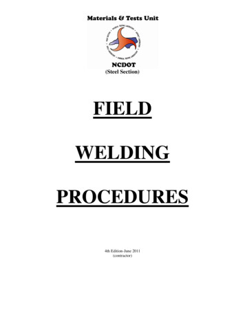
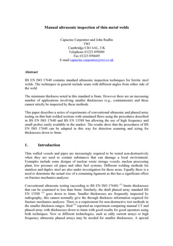
Ultrasonic Testing of Structural WeldsDEXTER A. OLSSON, Bethlehem Steel CorporationDuring the past five years Bethlehem Steel Corporation has developed and applied techniques for the ultrasonic testing of buttwelds which provides an assurance of weld quality similar tothat achieved with radiography. Although there are no revolutionary breakthroughs involved, a number of significant innovations permit a more repeatable weld test than has previouslybeen achieved with ultrasonics. The Bureau of Public Roadshas cooperated with Bethlehem Steel Corporation for severalyears in these developments. They have recently published atraining text and have permitted the use of the method in a recent circular memorandum. THE ULTRASONIC testing of welds is a much discussed but little used inspectiontechnique, which, in theory, offers significant advantages to both customer and fabricator. Bethlehem Steel Corporation has been using this inspection technique as a production tool for the last five years. Production work has provided the basis for a number of innovations in technique, equipment and inspection philosophy.In general, this work has been limited to the inspection of full penetration butt weldsin plate thicknesses from 5/16 in. to 5 in.Since the various innovations are interrelated in a complex manner, we shall arbitrarily discuss them in the order in the test in which they actually occur. Followingthis we will discuss auxiliary areas, namely calibration devices and defect locationaids. For reference purposes the basic ultrasonic weld testing scheme is described inFigure 1.Conventional pulse echo instrumentation is used. Pulse length controls are set atnear maximum values. Transducers of 2.25-mc frequency either 1h, by 1 in. or % in.square are generally used. Quartz has not been used as a transducer material. All ofthe common "ceramic" types are utilized.A search unit wedge design of the type shown in Figure 1 was chosen for two reasons.First, this design permits extremely close approach to the weld bead reinforcement.Second, internal wedge reflections are minimized, permitting interpretation of near defects when testing at high sensitivity. Figure 2 compares internal reflection noise forvarious angle search unit designs with information on the relative closeness of approachto weld bead reinforcements.All of the common couplants have been evaluated. Glycerine appears to be the bestaccording to our production experience. Theoretical considerations reinforce this observation. The close acoustical match between lucite and glycerine minimizes spuriouspropagation caused by surface roughness. The overall efficiency of glycerine as acouplant minimizes transmission efficiency variations caused by surface roughness. Itshould be emphasized that surface roughness variations have a much greater effect onlongitudinal beam testing than on shear wave testing for the same reasons of couplingefficiency. Therefore, angle beam tests of greater reliability can be conducted on rougher surfaces. These couplant effects are a result of transmission efficiencies (Table 1).Having introduced the sound pulse into the plate adjacent to the weld, the next matterto be considered is the angle at which the sound is propagated through the plate and intoPaper sponsored by Committee on Metals in Highway Structures and presented at the 48th AnnualMeeting.46
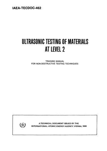
47Cathode Ray Tube Screen''·i .Approach ll"'Angle Wedge and Transducer arecollectively known as Search UnitType AApproach 3/8"Type BApproach 3/8"Figure 1. Basic ultrasonic weld testing scheme.Type D Approach 3/8"TypeCApproach o·the weld. It is believed that the flattestpossible testing angle should be used. TheFigure 2. Wedge noise and weld bead approach.basic reason for this choice is the fact thattypical production defects tend to be perpendicular to the plate surface or are associated with weld preparation surfaces. The choice of flatter angles offers severalother advantages. First, flatter angles result in more beam spread in the plate thickness. Second, flatter angles permit more of the weld volume to be inspected without resorting to bouncing the sound from the opposite plate surface. This is advantageoussince bouncing causes definite errors in defect location (1).The flattest angle we consider practical for weld inspection is 75 deg. Most testsare limited to 70 deg. Higher angles contain surface wave components which make interpretation difficult or impossible. The angles generally used for particular thicknessesare as follows:Thickness (in.)1/ to422 to 33 to 5Over 5Angle (deg)7070 or 6060 or 4545Steeper angles are used in heavier material for two reasons. The long sound pathneeded for flatter angles introduces more attenuation into the test than can be easilycompensated. Beam spread associated with flatter angles in heavy sections becomes adisadvantage, reducing defect detection reliability.The phenomenon of mode conversion isquite often discussed with regard to anglechoice. Mode conversion is not relatedspecifically to any testing angle but only toTABLE Ithe angle of sound incidence upon a reflectTranamissivlty (single interface)ing surface. The critical angle of incidenceLucite - glycerine85,85 Lucite - wateris 30 deg. Therefore, detection of vertical63 , o5iLucile - oil53.87ireflectors using a 60-deg angle is questionAugle beam testing tram1mlsslvityable.In practice, the only real precaution(1) Lucite glycerine steel15.24i(2) Lucite water steel1.10inecessarywhen using 60 deg is the strict(3) Lucite oil steel4.91%avoidance of plate edges or vertically drilledOverall transmission variation with surface variation(a 2 variation from a 101' dtrect luclte steel coupling condition)holes as calibration standards. Actually, 60(4) Lucite glycerine steel (&ht!!ar)D.96.,;deg is a good testing angle because many(5) Luette water steel (sh ar)3.65 (6) Lucile oll steel (shear)5.39 weld preparations involve 30-deg surfaces,(1) Quartz glycerine steel (longitudinal)12.63 which, as a lack of fusion, are ideally de-
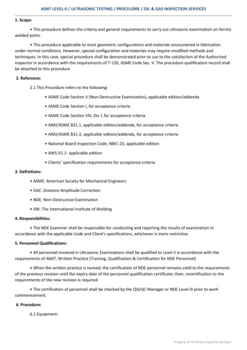
48TABLE 2Amplitude(db)De 2145270601999706045Plate Thickness(In.)Defect Length(ln.)(a) Defect Type Porosity76Not detected(b) Delect Type SlagFigure 3. Mode conversion effects.Large Reflecting AreaSmal Reflecting AreaFigure 4. Signal amplitude is a measure of defect reflecting area .888LO817813Not 451211701360451981 (c) Defect Type Lacko( Penetration5458Figure 5, Search unit trove I is a measure of defect length.70316028706045191812121 (e) Defect Type Lack of FusionDefect l.ocatiGn Chart1021041 151526201 1621706045217060451317132 2021Figure 6 . Defect location can be accurately done.tected with 60 deg. By the same token, 45 deg is a poor angle for the detection of lackof fusion for the same reasons. These effects are shown in Figure 3. Some data relating testing angle to defect detection reliability for actual defects are given in Table 2.When the pulse has traveled to the defect, been reflected and returned through thetransducer, it must be interpreted. There are six basic types of information which can
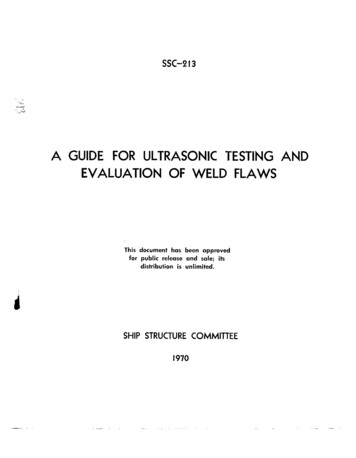
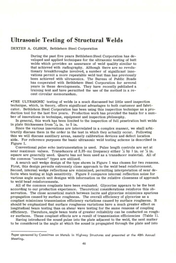
49Figure 7. Testing from both sides of weld revealsdefect orientation.Figure 8. Travel to and from the weld reveals defect height.be extracted. Figures 4 through 9 depictthese information types. We feel that thefirst three types of information are of primary importance in determining defectseverity and pinpointing defect locationRat DefectPomily Defectfor excavation. The other three types dealwith parameters not easily quantified andFigure 9. Pulse shape ind i cotes nature of defect.should not be used as a basis for acceptance or rejection. f{owever, these typesof information are of great value to thewelding engineer or supervisor who must intelligently correct defective weldingconditions.In order to establish a basis for amplitude rejection, it is necessary to develop dataon a great many defects. It was found that conventional methods of test standardizationand amplitude read out were not sufficiently accurate. Rather than attempt to judge theheight of signals on the screen, an attenuator (or calibrated gain control) was used. Theinstrument is calibrated on an arbitrary nondirectional reference reflector such as the1.5-mm hole in the IIW block. Defect amplitude is related to this reference by equatingall signal heights to that of the reference using an attenuator. The difference (in db) isnow amplitude information. CRT presentation, vertical linearity deviations, and visualerror are largely eliminated.Since CRT linearity limitations are eliminated, the clipping or reject control can nowbe used, not "to clean up the screen" but to decrease the vertical dynamic range presented on the CRT. This increases the accuracy of amplitude measurement using anattenuator still further.Using this approach, a gr eat many welding defects were measured, as shown in Figure 10. The attenuation within the material has been corrected by adding 2 db/in. afterthe first inch of sound travel to all readings. This value was obtained by making a greatmany readings on various steel thicknesses and reflector types. Figure 11 shows the lO2Ssignal sizein dKibels20db10O 1 l l 4 5 i I101Zl!51linchesISJOzo10db100.1 OJSU ll UIS1 1.5 ll I 510 11dtfH:l ltngthin indttsFigure JO. Weld tests at 70 deg: 120 defectsplate thickness 5/ 16 in. to 5 in.'-.inchescz:::::Js1.51. db/inch1Zl45&linchesFigure 11. Results of some attenuation tests.
50/ 7li .' "'. ' ,, .,,- [;. . '.:.,'- " I ,,Tr:.f-"'L-. ·· --1'Figure 12. Sensitivity standard.Figure 13. Distance calibration standard for anglebeam testing.results of some of these tests. Increasedattenuation is noted close to the search unitfor reflectors incorporating the cylindrical surfaces of drilled holes, as compared withflat-bottomed holes drilled at the testing angle. These geometrical effects apply only tocylindrical surfaces and care should be taken not to use such standards for attenuationmeasurements. In all cases, the attenuation is the slope of the curve.As was previously stated, the IIW block 1.5-mm hole has been used as a sensitivitystandard. Since different angles and resulting different path lengths introduce the geometrical effects, a simple standard, in which the distance to the reflector is l in. for70 deg, 60 deg and 45 deg, has been developed (Fig. 12).Defect length is measured conventionally based on the point at which a 5-db drop insignal is encountered.Defect location in cross section is accomplished using conventional geometricalmethods. IIW block distance calibration surfaces may be used. We have developed asimple calibration standard for distance which gives calibration pulses at even-inch increments. This standard is shown in Figure 13. We prefer to calibrate for actual soundpath length. We feel that the weld inspector is thus made more aware of the geometricswith which he is working. Having thus calibrated, a chart such as Figure 14 can be usedfor defect location. To further simplifythis procedure, we have developed a simpleretractable tape (Fig. 15) for each angle1Defect llist.e AllNd of S.t 5-a P*t345171DefectDe,th.,Figure 14. Defect location chart.Figure 15. Retractable tape for defect location.
51which becomes part of the search unit.The tape is pulled out to the equivalentpath length. At this point the defect isdirectly under the tape end and the defectdepth is read from a secondary scale opposite the observed path length dimension.As mentioned earlier, it is necessaryto correct for defect location errors whena bounce from the opposite plate surfaceis used. For angles greater than 45 deg,a small l::J. value must be subtracted fromthe apparent horizontal dimension (soundemission point to defect). There is nocorrection at 45 deg. At 60 deg, the correction is about 1/e in.; at 70 deg, about1,4in.Figure 16. Internally calibrated search unit.One of the pitfalls of ultrasonic weldtesting is the fact that the test is notself-calibrating. There is no back reflection or other continual reminder of testing uniformity. Normal shop line voltages andbattery-powered unit voltage variations near the end of battery life can cause gradualsensitivity changes which go unnoticed. We use constant voltage transformers and voltage drop alarms to protect us from these effects. In addition, we have developed aninternally calibrated search unit (Fig. 16) which provides a continual simple check ofamplitude and horizontal calibration stability. A hole is drilled in the wedge so that asmall amount of sound reflected from the contact surface will be in turn reflected fromthe hole. This results in a small discrete signal on the screen which can be used tomonitor testing uniformity. The reflector hole is threaded arid a screw inserted. Moving the screw changes reflector characteristics slightly. The screw is used to compensate for slight wedge wear.The nature of the data recorded in Figure 10 makes possible an ultrasonic weld inspection standard based on amplitude and length. Most present weld quality requirements can be interpreted in terms of amplitu!'.)e and length using such information. Thedata clearly indicate the factors which lend to ultrasonic weld inspection reliability indetecting the more ·serious defect types. Radiography has forced on us the necessity ofaccurate defect identification since generally the most serious defects are most poorlydetected. By its nature, ultrasonic testing reflects defect severity directly. Thereforedefect identification becomes much less important;Defect TypeCrackLack of fusionLack of penetrationSlagPorosityDefect SeveritylRadiographicUltrasonicS·mrtyThe most important part of the weld testing system is the inspector. Use of amplitude and length rejection criteria has removed from him the onus of defect decisionsbased purely on subjective observations. However, he must still have a detailed knowledge of ultrasonics and must be capable of working easily with complicated situationsin three-dimensional geometry.We give each of our weld inspectors a four- tofive-weekclassroom course to thisend. We have generally drawn on groups of radiographers qualified to 250-1500 or onexperienced draftsmen for our personnel.Our work in the area of ultrasonic weld testing over the past year has been in cooperation with the Bureau of Public Roads. We are developing a specification and a trainingmanual for the inspection of bridge weldments. The publication and implementation ofthis work should expand the use of ultrasonics as a weld testing tool.
52Generally, this ' ork has bee lin ited to full penetratio1 butt welds in thickness -s from5/1a in. to 5 in. We have also applied it to full penetration T-welds in the same thicknessrange. It would be dangerous to attempt to apply the results of this work to other weldconfigurations or thicknesses. Partial penetration welds and backing strip welds can bethus inspected but spurious reflections caused by these configurations must be taken into account. We are extremely dubious as to the direct application of this information tofillet welds.We hope that the result of our work will be greater use of ultrasonic weld testing.The use of amplitude and length rejection criteria will simplify interpretation. Eventually we may be able to treat particular areas in large welds more critically thanothers, depending upon the excellent defect location ability of ultrasonics to tell uswhether or not defects are in more highly stressed weld areas.REFERENCE1. Niklas, L. In Materials Testing, Aug. 1965.
THE ULTRASONIC testing of welds is a much discussed but little used inspection technique, which, in theory, offers significant advantages to both customer and fabri cator. Bethlehem Steel Corporation has been using this inspection technique as a pro duction tool for the last five