Transcription
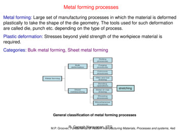
Bulk Forming ProcessesChapter 16ME-215 Engineering Materials and ProcessesVeljko Samardzic
16.1 Introduction Metal has been shaped by deformationprocesses for several thousand years Forging, rolling, and wire drawing wereperformed in the Middle Ages The Industrial Revolution allowed theseprocesses to be done at a higher level Recently, many processes have begun to beautomatedME-215 Engineering Materials and ProcessesVeljko Samardzic
16.2 Classification of DeformationProcesses Bulk deforming processes can be classified asprimary or secondary processes– Primary processes reduce a cast material into slabs,plates, and billets– Secondary processes reduce shapes into finished orsemifinished products Bulk deformation processes are those processeswhere the thickness or cross sections are reduced Sheet-forming operations involve the deformationof materials whose thickness and cross sectionremain relatively constantME-215 Engineering Materials and ProcessesVeljko Samardzic
16.3 Bulk Deformation Processes RollingForgingExtrusionWire, rod, and tube drawingCold forming, cold forging, and impactextrusion Piercing Squeezing processesME-215 Engineering Materials and ProcessesVeljko Samardzic
16.4 Rolling Rolling operations reduce the thickness orchange the cross section of a materialthrough compressive forces Often the first process that is used toconvert material into a finished wroughtproduct Thick stock can be rolled into blooms,billets, or slabsME-215 Engineering Materials and ProcessesVeljko Samardzic
Starting Stock Blooms have a square or rectangular crosssection Billets are usually smaller than a bloom andcan have a square or circular cross section– Can be further rolled into structural shapes Slabs are a rectangular solid with a widthgreater than twice the thickness– Can be used to produce plates, sheets, or stripsME-215 Engineering Materials and ProcessesVeljko Samardzic
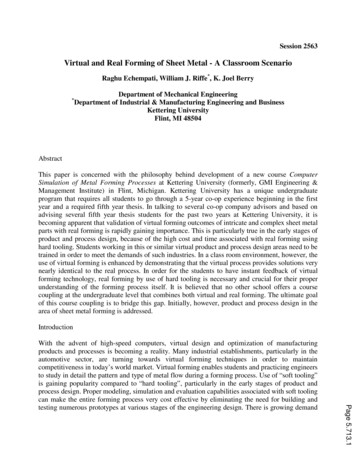
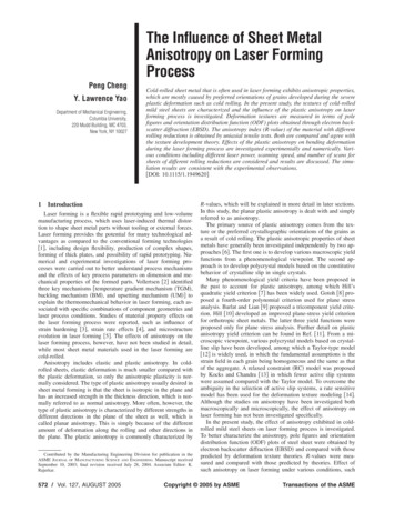
Flowchart of Rolling OperationsFigure 16-1 Flow chart forthe production of variousfinished and semifinishedsteel shapes. Note theabundance of rollingoperations. (Courtesy ofAmerican Iron and SteelInstitute, Washington, D.C.)ME-215 Engineering Materials and ProcessesVeljko Samardzic
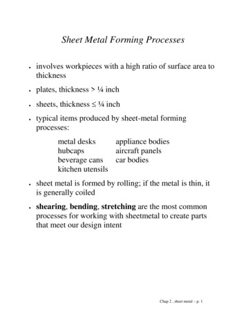
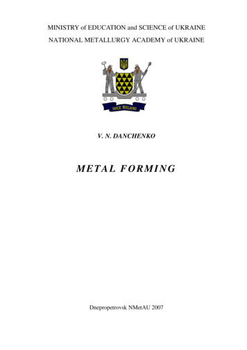
Basic Rolling Process Metal is passedbetween two rolls thatrotate in oppositedirections Friction acts to propelthe material forward Metal is squeezed andelongates tocompensate for thedecrease in crosssectional areaME-215 Engineering Materials and ProcessesFigure 16-2 Schematic representation of the hotrolling process, showing the deformation andrecrystallization of the metal being rolled.Veljko Samardzic
Hot Rolling and Cold Rolling In hot rolling, temperature control isrequired for successful forming– Temperature of the material should be uniform– Rolling is terminated when the temperature fallsto about 50 to 100 degrees above therecrystallization temperature– Ensures the production of a uniform grain size Cold rolling products sheet, strip, bar androd products with smooth surfaces andaccurate dimensionsME-215 Engineering Materials and ProcessesVeljko Samardzic
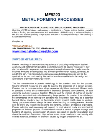
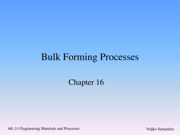
Rolling Mill ConfigurationsFigure 16-3 Variousroll configurationsused in rollingoperations.ME-215 Engineering Materials and ProcessesVeljko Samardzic
Rolling Mill Configurations Smaller diameter rollsproduce less length ofcontact for a givenreduction and require lessforce to produce a givenchange in shape Smaller cross sectionprovides a reducedstiffnessFigure 16-4 The effect of roll diameter on lengthof contact for a given reduction.– Rolls may be prone toflex elastically becausethey are only supportedon the endsME-215 Engineering Materials and ProcessesVeljko Samardzic
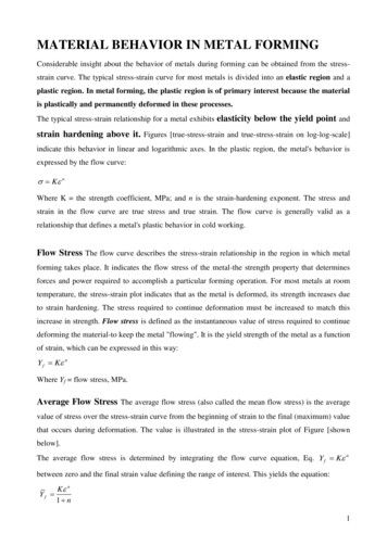
Continuous (Tandem) RollingMills Billets, blooms, andslabs are heated andfed through anintegrated series ofnonreversing rollingmills Synchronization ofrollers may pose issuesME-215 Engineering Materials and ProcessesFigure 16-5 Typical roll-pass sequences used inproducing structural shapes.Veljko Samardzic
Ring Rolling One roll is placed throughthe hole of a thick-walledring and a second rollpresses on the outside Produces seamless rings Circumferential grainorientation and is used inrockets, turbines,airplanes, pressure vessels,and pipelinesME-215 Engineering Materials and ProcessesFigure 16-6 Schematic of horizontal ring rollingoperation. As the thickness of the ring isreduced, its diameter will increase.Veljko Samardzic
Characteristics, Quality, andPrecision of Rolled Products Hot-rolled products have little directionalityin their properties Hot-rolled products are therefore uniformand have dependable quality– Surfaces may be rough or may have a surfaceoxide known as mill scale Dimensional tolerances vary with the kindof metal and the size of the product Cold-rolled products exhibit superiorsurface finish and dimensional precisionME-215 Engineering Materials and ProcessesVeljko Samardzic
Flatness Control and RollingDefects Rollers must be evenlyspaced throughout forperfectly flat pieces toFigure 16-7 (above) (a) Loading on a rolling mill roll.be producedThe top roll is pressed upward in the center whilebeing supported on the ends. (b) The elastic Sometimes thisresponse to the three-point bending.variation in roller“flatness” may bedesiredFigure 16-8 Use of a “crowned” roll to compensate forroll flexure. When the roll flexes in three-point bending,the crowned roll flexes into flatness.ME-215 Engineering Materials and ProcessesVeljko Samardzic
Thermomechanical Processing andControlled Rolling Heat may be used to reduce forces andpromote plasticity, but heat treatments aretypically subsequent operations Thermomechanical processing combines thedeformation and thermal processing into asingle shape with the desired properties Requires computer-controlled facilities Substantial energy savingsME-215 Engineering Materials and ProcessesVeljko Samardzic
16.5 Forging Processes that induce plastic deformationthrough localized compressive forcesapplied through dies Oldest known metalworking process Parts can range in size Methods– Drawing– Upset– Squeezed in closed impression diesME-215 Engineering Materials and ProcessesVeljko Samardzic
Open-die Hammer Forging Same type of forging done by a blacksmithbut mechanical equipment performs theoperation An impact is delivered by some type ofmechanical hammer Simplest industrial hammer is a gravitydrop machine Computer controlled-hammers can providevarying blowsME-215 Engineering Materials and ProcessesVeljko Samardzic
Open-die Hammer ForgingFigure 16-9 (Left) Double-frame drop hammer.(Courtesy of Erie Press Systems, Erie, PA.)(Right) Schematic diagram of a forging hammer.ME-215 Engineering Materials and ProcessesVeljko Samardzic
Figure 16-10 (Top)Illustration of theunrestrained flow ofmaterial in open-dieforging. Note thebarrel shape thatforms due to frictionbetween the die andmaterial. (Middle)Open-die forging of amultidiameter shaft.(Bottom) Forging of aseamless ring by theopen-die method.(Courtesy of ForgingIndustry Association,Cleveland, OH.)ME-215 Engineering Materials and ProcessesVeljko Samardzic
Impression-Die Hammer Forging The dies are shaped to control the flow of metal Upper piece attaches to the hammer and the lowerpiece to the anvil Metal flows and completely fills the dieFigure 16-11 Schematic of theimpression-die forging process,showing partial die filling and thebeginning of flash formation in thecenter sketch and the final shapewith flash in the right-hand sketch.ME-215 Engineering Materials and ProcessesVeljko Samardzic
Impression-Die Hammer Forging Excess metal may squeeze out of the die– This metal is called flash Flashless forging can be performed if the metal isdeformed in a cavity that provides totalconfinement Many forged products are produced with a seriesof cavities– First impression is called edging, fullering, or bending– Intermediate impressions are for blocking the metal toapproximately its final shape– Final shape is given in its final forging operationME-215 Engineering Materials and ProcessesVeljko Samardzic
Figure 16-12Impression drop-forgingdies and the productresulting from eachimpression. The flash istrimmed from thefinished connecting rodin a separate trimmingdie. The sectional viewshows the grain flowresulting from theforging process.(Courtesy of ForgingIndustry Association,Cleveland, OH.)ME-215 Engineering Materials and ProcessesVeljko Samardzic
Alternatives to Hammer and AnvilArrangement Two hammers may form a workpiece Impactors operate with less noise and lessvibrationFigure 16-13 Schematic diagram of an impactor in the striking and returning modes. (Courtesy ofChambersburg Engineering Company, Chambersburg, PA)ME-215 Engineering Materials and ProcessesVeljko Samardzic
Press Forging Press forging is used for large or thickproducts Slow squeezing action penetratescompletely through the metal– Produces a more uniform deformation and flow– Longer time of contact between the die andworkpiece Dies may be heated (isothermal forging) Presses are either mechanical or hydraulicME-215 Engineering Materials and ProcessesVeljko Samardzic
Design of Impression-Die Forgingsand Associated Tooling Forging dies are typically made of high-alloy ortool steel Rules for better and more economical parts:– Dies should part along a single, flat plane or follow the contour ofthe part– Parting surface should be a plane through the center of the forging– Adequate draft– Generous fillets and radii– Ribs should be low and wide– Various cross sections should be balanced– Full advantage should be taken of fiber flow lines– Dimensional tolerances should not be closer than necessaryME-215 Engineering Materials and ProcessesVeljko Samardzic
Impression-Die Forgings Important design details–––––Number of intermediate stepsShape of each stepAmount of excess metal to fill the dieDimensions of flash at each stepGood dimensional accuracyFigure 16-15 A forged-andmachined automobileengine crankshaft that hasbeen formed frommicroalloyed steel.Performance is superior tocranks of cast ductile iron.ME-215 Engineering Materials and ProcessesVeljko Samardzic
Upset Forging Increases the diameter of a material by compressing itslength Both cold and hot upsetting Three rules of upset forging 1. The length of the unsupported material that can be gathered or upsetin one blow without injurious buckling should be limited to three timesthe diameter of the bar.2. Lengths of stock greater than three times the diameter may be upsetsuccessfully provided that the diameter of the upset is not more than 1times the diameter of the bar.3. In an upset requiring stock length greater than three times thediameter of the bar, and where the diameter of the cavity is not morethan 1 times the diameter of the bar (the conditions of rule 2), thelength of the unsupported metal beyond the face of the die must notexceed the diameter of the bar.ME-215 Engineering Materials and ProcessesVeljko Samardzic
Upset ForgingFigure 16-17 Schematics illustrating the rules governing upset forging. (Courtesy of NationalMachinery Company, Tiffin, OH.)ME-215 Engineering Materials and ProcessesVeljko Samardzic
Automatic Hot Forging Slabs, billets, andblooms can be slid intoone end of a room andhot-forged products canemerge at the other end,with every processautomatedFigure 16-18 (a) Typical four-step sequence to produce a spur-gear forging by automatic hot forging.The sheared billet is progressively shaped into an upset pancake, blocker forging, and finished gearblank. (b) Samples of ferrous parts produced by automatic hot forging at rates between 90 and 180parts per minute. (Courtesy of National Machinery Company, Tiffin, OH.)ME-215 Engineering Materials and ProcessesVeljko Samardzic
Roll Forging Round or flat bar stockis reduced in thicknessand increased in length Produces productssuch as axles, taperedlevers, and leaf springs Little or no flash isproducedFigure 16-19 (Top) Roll-forging machine in operation.(Right) Rolls from a roll-forging machine and thevarious stages in roll forging a part. (Courtesy of AjaxManufacturing Company, Euclid, OH)ME-215 Engineering Materials and ProcessesVeljko Samardzic
Swaging Also known as rotaryswaging and radialforging Uses externalhammering to reducethe diameter orproduce tapers orpoints on round barsof tubesME-215 Engineering Materials and ProcessesFigure 16-20 Schematic of the roll-forging processshowing the two shaped rolls and the stock beingformed. (Courtesy of Forging Industry Association,Cleveland, OH.)Veljko Samardzic
SwagingFigure 16-23 (Below) A variety of swaged parts,some with internal details. (Courtesy of CincinnatiMilacron, Inc. Cincinnati, OH.)Figure 16-21 (Below) Tube being reduced in arotary swaging machine. (Courtesy of the TimkinCompany, Canton, OH.)Figure 16-22 (Right) Basic components and motionsof a rotary swaging machine. (Note: The cover platehas been removed to reveal the interior workings.)(Courtesy of the Timkin Company, Canton, OH.)ME-215 Engineering Materials and ProcessesVeljko Samardzic
Net-Shape and Near-Net-ShapeForging 80% of the cost of a forged-part can be dueto post-forging operations To minimize expense and waste, partsshould be forged as close the final shape aspossible These processes are known as net-shape orprecision forgingME-215 Engineering Materials and ProcessesVeljko Samardzic
16.6 Extrusion Metal is compressed andforced to flow through ashaped die to form aproduct with a constantcross section May be performed hot orcold A ram advances from oneend of the die and causesthe metal to flowplastically through the die Commonly extrudedmetals: aluminum,magnesium, copper, andleadME-215 Engineering Materials and ProcessesFigure 16-25 Direct extrusion schematic showingthe various equipment components. (Courtesy ofDanieli Wean United, Cranberry Township, PA.)Veljko Samardzic
Typical Extruded ProductsFigure 16-26 Typical shapes produced by extrusion. (Left) Aluminum products. (Courtesy ofAluminum Company of America, Pittsburgh, PA.) (Right) Steel products. (Courtesy of AlleghenyLudlum Steel Corporation, Pittsburgh, PA.)ME-215 Engineering Materials and ProcessesVeljko Samardzic
Advantages of Extrusion Many shapes can be produced that are notpossible with rolling No draft is required Amount of reduction in a single step is onlylimited by the equipment, not the materialor the design Dies are relatively inexpensive Small quantities of a desired shape can beproduced economicallyME-215 Engineering Materials and ProcessesVeljko Samardzic
Extrusion Methods Direct extrusion– Solid ram drives the entire billet to and through a stationarydie– Must provide power to overcome friction Indirect extrusion– A hollow ram pushes the die back through a stationary,confined billetFigure 16-27 Direct and indirect extrusion. In direct extrusion, the ram and billet both move andfriction between the billet and the chamber opposes forward motion. For indirect extrusion, the billet isstationary. There is no billet-chamber friction, since there is no relative motion.ME-215 Engineering Materials and ProcessesVeljko Samardzic
Forces in Extrusion Lubrication is importantto reduce friction andact as a heat barrier Metal flow in extrusion– Flow can be complex– Surface cracks, interiorcracks and flow-relatedcracks need to bemonitoredFigure 16-28 Diagram of the ram force versus ramposition for both direct and indirect extrusion of the– Process control issame product. The area under the curve correspondsto the amount of work (force x distance) performed.importantThe difference between the two curves is attributed tobillet-chamber friction.ME-215 Engineering Materials and ProcessesVeljko Samardzic
Extrusion of Hollow Shapes Mandrels may be usedto produce hollowshapes or shapes withmultiple longitudinalcavitiesFigure 16-30 Two methods of extruding hollow shapesusing internal mandrels. In part (a) the mandrel and ramhave independent motions; in part (b) they move as asingle unit.ME-215 Engineering Materials and ProcessesVeljko Samardzic
Hydrostatic Extrusion High-pressure fluidsurrounds the workpieceand applies the force toexecute extrusion– Billet-chamber friction iseliminated High efficiency process Temperatures are limitedbecause the fluid acts as aheat sink Seals must be designed tokeep the fluid fromleakingME-215 Engineering Materials and ProcessesFigure 16-32 Comparison of conventional (left)and hydrostatic (right) extrusion. Note theaddition of the pressurizing fluid and the O-ringand miter-ring seals on both the die and ram.Veljko Samardzic
Continuous Extrusion Conform process– Continuous feedstock isfed into a grooved wheeland is drive by surfacefriction into a chambercreated by a mating diesegment– The material upsets toconform to the chamber– Feedstock can be solid,metal powder, punchouts,or chips– Metallic and nonmetallicpowders can be intimatelymixedME-215 Engineering Materials and ProcessesFigure 16-33 Cross-sectional schematic of theConform continuous extrusion process. Thematerial upsets at the abutment and extrudes.Section x-x shows the material in the shoe.Veljko Samardzic
16.7 Wire, Rod, and TubeDrawing Reduce the cross section of a material bypulling it through a die Similar to extrusion, but the force is tensileFigure 16-34 Schematic drawing of the rod-or bardrawing process.ME-215 Engineering Materials and ProcessesFigure 16-36 Cold-drawing smaller tubingfrom larger tubing. The die sets the outerdimension while the stationary mandrel sizesthe inner diameter.Veljko Samardzic
Tube and Wire Drawing Tube sinking does notuse a mandrel– Internal diameterprecision is sacrificedfor cost and a floatingplug is usedFigure 16-37 (Above) Tube drawing witha floating plug.Figure 16-38 Schematic of wire drawing with arotating draw block. The rotating motor on thedraw block provides a continuous pull on theincoming wire.ME-215 Engineering Materials and ProcessesVeljko Samardzic
Figure 16-39 Cross sectionthrough a typical carbidewire-drawing die showing thecharacteristic regions of thecontour.Figure 16-40 Schematic of a multistation synchronized wire-drawing machine. To preventaccumulation or breakage, it is necessary to ensure that the same volume of material passes througheach station in a given time. The loops around the sheaves between the stations use wire tensionsand feedback electronics to provide the necessary speed control.ME-215 Engineering Materials and ProcessesVeljko Samardzic
16.8 Cold Forming, Cold Forging,and Impact Extrusion Slugs of material aresqueezed into orextruded from shapeddie cavities to producefinished parts ofprecise shape and size Cold heading is a formof upset forging– Used to make theenlarged sections on theends of rod or wire (i.e.heads of nails, bolts,etc.)ME-215 Engineering Materials and ProcessesFigure 16-41 Typical steps in a shearing and coldheading operation.Veljko Samardzic
Impact Extrusion A metal slug ispositioned in a diecavity where it isstruck by a singleblow Metal may flowforward, backward orsome combination The punch controls theinside shape while thedie controls theexterior shapeME-215 Engineering Materials and ProcessesFigure 16-43 Backward and forward extrusionwith open and closed dies.Veljko Samardzic
Cold ExtrusionFigure 16-44(a) Reverse(b) forward(c) combinedforms of coldextrusion.(Courtesy theAluminumAssociation,Arlington, VA.)Figure 16-45(Right) Steps inthe forming of abolt by coldextrusion, coldheading, andthread rolling.(Courtesy ofNationalMachinery Co.Tiffin, OH.)ME-215 Engineering Materials and ProcessesVeljko Samardzic
Figure 16-46 Cold-forming sequence involvingcutoff, squaring, two extrusions, an upset, and atrimming operation. Also shown are the finishedpart and the trimmed scrap. (Courtesy of NationalMachinery Co., Tiffin, OH.)ME-215 Engineering Materials and ProcessesFigure 16-47 Typical parts made by upsettingand related operations. (Courtesy of NationalMachinery Co., Tiffin, OH.)Veljko Samardzic
16.9 Piercing Thick-walled seamless tubing can be made byrotary piercing Heated billet is fed into the gap between two large,convex-tapered rolls Forces the billet to deform into a rotating ellipseFigure 16-50 (Left)Principle of theMannesmann process ofproducing seamless tubing.(Courtesy of AmericanBrass Company,Cleveland, OH.) (Right)Mechanism of crackformation in theMannesmann process.ME-215 Engineering Materials and ProcessesVeljko Samardzic
16.10 Other Squeezing Processes Roll extrusion- thin walled cylinders are producedfrom thicker-wall cylinders Sizing-involves squeezing all or select regions ofproducts to achieve a thickness or enhancedimensional precision Riveting- permanently joins sheets or plates ofmaterial by forming an expanded head on theshank end of a fastener Staking-permanently joins parts together when asegment of one part protrudes through a hole inthe otherME-215 Engineering Materials and ProcessesVeljko Samardzic
Other Squeezing ProcessesFigure 16-51 Theroll-extrusionprocess: (a) withinternal rollersexpanding the innerdiameter; (b) withexternal rollersreducing the outerdiameter.Figure 16-54Permanentlyattaching a shaftto a plate bystaking.Figure 16-52 Joiningcomponents by riveting.ME-215 Engineering Materials and ProcessesVeljko Samardzic
Other Squeezing Operations Coining- cold squeezingof metal while all of thesurfaces are confinedwithin a set of dies Hubbing- plasticallyforms recessed cavitiesin a workpieceFigure 16-55 The coining process.Figure 16-56 Hubbing a die block in a hydraulicpress. Inset shows close-up of the hardened huband the impression in the die block. The die blockis contained in a reinforcing ring. The uppersurface of the die block is then machined flat toremove the bulged metal.ME-215 Engineering Materials and ProcessesVeljko Samardzic
16.11 Surface Improvement byDeformation Processing Deformation processes can be used to improve oralter the surfaces of the metal Peening- mechanical working of surfaces byrepeated blows of impelled shot or a round-nosetool Burnishing- rubbing a smooth, hard object underpressure over the minute surface irregularities Roller burnishing- used to improve the size andfinish of internal and external cylindrical andconical surfacesME-215 Engineering Materials and ProcessesVeljko Samardzic
Summary There are a variety of bulk deformationprocesses The main processes are rolling, forging,extrusion, and drawing Each has limits and advantages as to itscapabilities The correct process depends on the desiredshape, surface finish, quantity, etc.ME-215 Engineering Materials and ProcessesVeljko Samardzic
Bulk Forming Processes Chapter 16. ME-215 Engineering Materials and Processes Veljko Samardzic 16.1 Introduction Metal has been shaped by deformation processes for several th