Transcription
MATERIAL BEHAVIOR IN METAL FORMINGConsiderable insight about the behavior of metals during forming can be obtained from the stressstrain curve. The typical stress-strain curve for most metals is divided into an elastic region and aplastic region. In metal forming, the plastic region is of primary interest because the materialis plastically and permanently deformed in these processes.The typical stress-strain relationship for a metal exhibits elasticity below the yield point andstrain hardening above it. Figures [true-stress-strain and true-stress-strain on log-log-scale]indicate this behavior in linear and logarithmic axes. In the plastic region, the metal's behavior isexpressed by the flow curve: K nWhere K the strength coefficient, MPa; and n is the strain-hardening exponent. The stress andstrain in the flow curve are true stress and true strain. The flow curve is generally valid as arelationship that defines a metal's plastic behavior in cold working.Flow Stress The flow curve describes the stress-strain relationship in the region in which metalforming takes place. It indicates the flow stress of the metal-the strength property that determinesforces and power required to accomplish a particular forming operation. For most metals at roomtemperature, the stress-strain plot indicates that as the metal is deformed, its strength increases dueto strain hardening. The stress required to continue deformation must be increased to match thisincrease in strength. Flow stress is defined as the instantaneous value of stress required to continuedeforming the material-to keep the metal "flowing". It is the yield strength of the metal as a functionof strain, which can be expressed in this way:Y f K nWhere Yf flow stress, MPa.Average Flow Stress The average flow stress (also called the mean flow stress) is the averagevalue of stress over the stress-strain curve from the beginning of strain to the final (maximum) valuethat occurs during deformation. The value is illustrated in the stress-strain plot of Figure [shownbelow].The average flow stress is determined by integrating the flow curve equation, Eq. Y f K nbetween zero and the final strain value defining the range of interest. This yields the equation:Yf K n1 n1
Where Y f average flow stress, MPa; and maximum strain value during the deformationprocess.FIGURE: Stress-strain curve indicating location of average flow stress Y f in relation to yieldstrength Y and final flow stress Yf.TEMPERATURE IN METAL FORMINGThe flow curve is a valid representation of stress-strain behavior of a metal during plasticdeformation, particularly for cold working operations. For any metal, the values of K and n dependon temperature. Both strength and strain hardening are reduced at higher temperatures. In additionductility is increased at higher temperatures. These changes are important because any deformationoperation can be accomplished with lower forces and power at elevated temperature. There arethree temperature ranges: cold, warm, and hot working.Cold Working Cold working (also known as cold forming) is metal forming performed at roomtemperature or slightly above. Significant advantages of cold forming compared to hot working are(1) better accuracy, meaning closer tolerances; (2) better surface finish; (3) strain hardeningincreases strength and hardness of the part; (4) grain flow during deformation provides theopportunity for desirable directional properties to be obtained in the resulting product; and (5) noheating of the work is required, which saves on furnace and fuel costs and permits higherproduction rates to be achieved. Owing to this combination of advantages, many cold formingprocesses have developed into important mass-production operations. They provide close tolerancesand good surfaces, minimizing the amount of machining required and permitting these operations tobe classified as net shape or near net shape processes.2
There arecertain disadvantages or limitations associatedwith cold-formingoperations: (1) higher forces and power are required to perform the operation; (2) care must betaken to ensure that the surfaces of the starting work piece are free of scale and dirt; and (3)ductility and strain hardening of the work metal limit the amount of forming that can be done to thepart. In some operations, the metal must be annealed in order to allow further deformation to beaccomplished. In other cases, the metal is simply not ductile enough to be cold worked.To overcome the strain hardening problem and reduce force and power requirements, many formingoperations are performed at elevated temperatures. There are two elevated temperature rangesinvolved, giving rise to the terms warm working and hot working.Warm Working Because plastic deformation properties are normally enhanced by increasing workpiece temperature, forming operations are sometimes performed at temperatures somewhat aboveroom temperature but below the recrystallization temperature. The term warm working is applied tothis second temperature range. The dividing line between cold working and warm working is oftenexpressed in terms of the melting point for the metal. The dividing line is usually taken to be 0.3Tm, where Tm is the melting point (absolute temperature) for the particular metal.The lower strength and strain hardening, as well as higher ductility of the metal at the intermediatetemperatures, provide warm working with the following advantages over cold working: (1) lowerforces and power, (2) more intricate work geometries possible, and (3) need for annealing may bereduced or eliminated.Hot Working Hot working (also called hot forming) involves deformation at temperaturesabove the recrystallization temperature. The recrystallization temperature for a given metal isabout one-half of its melting point on the absolute scale. In practice, hot working is usuallycarried out at temperatures somewhat above 0.5Tm. The work metal continues to soften astemperature is increased beyond 0.5 Tm, thus enhancing the advantage of hot working above thislevel.However, the deformation process itself generates heat which increases work temperatures inlocalized regions of the part. This can cause melting in these regions, which is highly undesirable.Also, scale on the work surface is accelerated at higher temperatures. Accordingly, hot workingtemperatures are usually maintained within the range 0.5Tm to 0.75Tm. Themost significantadvantage of hot working is the capability to produce substantial3
plastic deformation of the metal-far more than is possible with coldworking or warm working. The principal reason for this is that the flow curve of the hotworked metal has a strength coefficient that is substantially less than at room temperature, the strainhardening exponent is zero (at least theoretically), and the ductility of the metal is significantlyincreased. All of this results in the following advantages relative to cold working: (1) the shape ofthe work part can be significantly altered; (2) lower forces and power are required to deform themetal; (3) metals that usually fracture in cold working can be hot formed; (4) strength properties aregenerally isotropic because of the absence of the oriented grain structure typically created in coldworking; and (5) no strengthening of the part occurs from work hardening. This last advantage mayseem inconsistent, since strengthening of the metal is often considered an advantage for coldworking. However, there are applications in which it is undesirable for the metal to be workhardened because it reduces ductility; for example, if the part is to be subsequently processed bycold forming. Disadvantages of hot working include lower dimensional accuracy, higher totalenergy required (due to the thermal energy to heat the work piece), work surface oxidation (scale),poorer surface finish, and shorter tool life.Recrystallization of the metal in hot working involves atomic diffusion, which is a time-dependentprocess. Metal-forming operations are often performed at high speeds that do not allow sufficienttime for complete recrystallization of the grain structure during the deformation cycle itself.However, because of the high temperatures, recrystallization eventually does occur. It may occurimmediately following the forming process or later, as the work piece cools. Even ifrecrystallization occurs after the actual deformation, its eventual occurrence-together with thesubstantial softening of the metal at high temperatures-distinguishes hot working from warmworking or cold working.STRAIN RATE SENSITIVITYTheoretically, a metal in hot working behaves like a perfectly plastic material, with strain hardeningexponent n 0. This means that the metal should continue to flow under the same level of flowstress, once that stress level is reached. However, there is an additional phenomenon thatcharacterizes the behavior of metals during deformation, especially at the elevated temperatures ofhot working.That phenomenon is strain-rate sensitivity.Let us begin ourdiscussion of this topic by defining strain rate.4
The rate at which the metal is strained in a forming process is directly related to the speed ofdeformation v. In many forming operations, deformation speed is equal to the velocity of the ramor other moving element of the equipment. It is most easily visualized in a tensile test as thevelocity of the testing machine head relative to its fixed base.Given the deformation speed, strain. rate is defined:vh.Where true strain rate, m/s/m, or simply s-1 and h instantaneous height of the work piece beingdeformed, m. If deformation speedv is constant during the operation, strain rate will change as hchanges. In most practical forming operations, valuation of strain rate is complicated by thegeometry of the work part and variations in strain rate in different regions of the part. Strain rate canreach 1000 s-1or more for some metal forming processes such as high speed rolling and forging.We have already observed that the flow stress of a metal is a function of temperature. At thetemperatures of hot working, flow stress depends on strain rate. The effect of strain rate onstrength properties is known as strain-rate sensitivity. The effect can be seen in Figure.As strain rate is increased, resistance to deformation increases. This usually plots approximately asa straight line on a log-log graph, thus leading to the relationship:.Yf C m[4]Where C is the strength constant (similar but not equal to the strength coefficient in the flow curveequation), and m is the strain-rate sensitivity exponent. The value of C is determined at a strain rateof 1.0 and m is the slope of the curve in Figure (b).5
(a) Effect of strain rate on flow stress at in elevated work temperature. (b) Samerelationship plotted on log-log coordinatesThe effect of temperature on the parameters of Eq. (4) is pronounced. Increasing temperaturedecreases the value of C (consistent with its effect on K in the flow curve equation) and increasesthe value of m. The general result can be seen in Figure [shown below]. At room temperature, theeffect of strain rate is almost negligible; indicating that the flow curve is a good representation ofthe material behavior. As temperature is increased, strain rate plays a more important role indetermining flow stress, as indicated by the steeper slopes of the strain rate relationships. This isimportant in hot working because deformation resistance of the material increases so dramaticallyas strain rate is increased.FIGURE: Effect of temperature on flow stress for a typical metal. The constant C in Eq.(4),indicated by the intersection of each plot with the vertical dashed line at strain rate 1.0,decreases, and m (slope of each plot) increases with increasing temperature.6
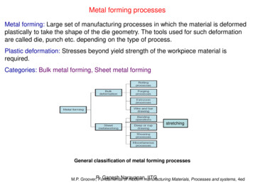
Rollingis the process of reducing the thickness or changing the cross-section of a longworkpiece by compressive forces applied through a set of rolls (Fig.), similar to rolling dough witha rolling pin to reduce its thickness. Rolling, which accounts for about 90 percent of all metalsproduced by metalworking processes, was first developed in the late 1500s. The basic operation isflat rolling, or simply rolling, where the rolled products are flat plate and sheet.Figure: Schematic outline of various flat- and shape-rolling processes.Source: American Iron and Steel Institute.Plates, which are generally regarded as having a thickness greater than 6 mm, are used forstructural applications such as ship hulls, boilers, bridges, girders, machine structures, and7
nuclear vessels. Plates can be as much as 0.3 m thick for the supports for large boilers, 150 mm forreactor vessels, and 100-125 mm for battleships and tanks.Sheets are generally less than 6 mm thick and are used for automobile bodies, appliances,containers for food and beverages, and kitchen and office equipment.Commercial aircraft fuselages are usually made of a minimum of 1 mm thick aluminum-alloy sheet.For example, skin thickness of a Boeing 747 is 1.8 mm and for the Lockheed Ll0ll it is 1.9 mm.Aluminum beverage cans are now made from sheets 0.28 mm in thickness, reduced to a final canwall thickness of 0.1 mm. Aluminum foil used to wrap candy has a thickness of 0.008 mm. Sheetsare provided to manufacturing facilities as flat pieces or as strip in coils for further processing intoproducts.Flat RollingA schematic illustration of the flat rolling process is shown in Fig. a. A strip of thickness ho entersthe roll gap and is reduced to hf by a pair of rotating rolls, each roll being powered through its ownshaft by electric motors. The surface speed of the roll is Vr. The velocity of the strip increases fromits initial value of Vo as it moves through the roll gap, just as fluid flows faster as it moves through aconverging channel. The velocity of the strip is highest at the exit of the roll gap and is denoted asVf. Since the surface speed of the roll is constant, there is relative sliding between the roll and thestrip along the arc of contact in the roll gap L. At one point along the contact length, the velocity ofthe strip is the same as that of the roll. This is called the neutral, or no slip, point. To the left ofthis point, the roll moves faster than the strip, and to the right of this point, the strip movesfaster than the roll. Hence the frictional forces, which oppose motion, act on the strip as shown inFig. b.Frictional forcesThe rolls pull the material into the roll gap through a net frictional force on the material. You cansee that this net frictional force must be to the right in Fig. b, and consequently the frictional forceon the left of the neutral point must be higher than the force on the right.8
As you can see, friction is needed to roll materials. However, energy is dissipated in overcomingfriction, so increasing friction means increasing forces and power consumption. Furthermore, highfriction could damage the surface of the rolled product.Flat Rolling and Its AnalysisFlat rolling is illustrated in Figures. It involves the rolling of slabs, strips, sheets, and plates-workparts of rectangular cross-section in which the width is greater than the thickness. In flat rolling, thework is squeezed between two rolls so that its thickness is reduced by an amount called the draft:d ho - hf(1)Where d draft, mm; ho starting thickness, mm; and hf final thickness, mm. Draft is sometimesexpressed as a fraction of the starting stock thickness, called the reduction:r d/ho(2)Where r reduction. When a series of rolling operations are used, reduction is taken as the sum ofthe drafts divided by the original thickness.In addition to thickness reduction, rolling usually increases work width. This is called spreading,and it tends to be most pronounced with low width-to-thickness ratios and low coefficients offriction. Conservation of material is preserved, so the volume of metal exiting the rolls equals thevolume entering:howoLo hfwfLf(3)Where wo and wf are the before and after work widths, mm; and Lo and Lf are the before and afterwork lengths, mm. Similarly, before and after volume rates of material flow must be the same, sothe before and after velocities can be related:howovo hfwfvf(4)Where vo and vf are the entering and exiting velocities of the work.The rolls contact the work along a contact arc defined by the angle α. Each roll has radius R, and itsrotational speed gives it a surface velocity vr. This velocity is greater than the entering speed of thework vo and less than its exiting speed vf. Since the metal flow is continuous, there is a gradualchange in velocity of the work between the rolls.However, there is one point along the arc where work velocity equals roll velocity. This iscalled the no-slip point, also known as the neutral point. On either side of this point, slipping and9
friction occur between roll and work. The amount of slip between the rolls and the work can bemeasured by means of the forward slip, a term used in rolling that is defined:s vf- vr / vr(5)Where s forward slip; vf final (exiting) work velocity, m/s; and vr roll speed, m/s.The true strain experienced by the work in rolling is based on before and after stock thicknesses. Inequation form,ε ln ho/hf(6)The true strain can be used to determine the average flow stress Y f applied to the work material inflat rolling. Recall from the previous chapter, Eq., thatnY f Kε / 1 n(7)The average flow stress will be useful to compute estimates of force and power in rolling.Friction in rolling occurs with a certain coefficient of friction, and the compression force of therolls, multiplied by this coefficient of friction, results in a friction force between the rolls and thework. On the entrance side of the no-slip point, friction force is in one direction, and on the otherside it is in the opposite direction. However, the two forces are not equal. The friction force on theentrance side is greater, so that the net force pulls the work through the rolls. If this were notthe case, rolling would not be possible. There is a limit to the maximum possible draft that canbe accomplished in flat rolling with a given coefficient of friction, given by:dmax µ2R(8)Where dmax maximum draft, mm; µ coefficient of friction; and R roll radius mm. The equationindicates that if friction were zero, draft would be zero, and it would be impossible to accomplishthe rolling operation.Coefficient of friction in rolling depends on lubrication, work material, and working temperature. Incold rolling, the value is around 0.1; in warm working, a typical value is around 0.2; and in hotrolling, J.L is around 0.4. Hot rolling is often characterized by a condition called sticking, in whichthe hot work surface adheres to the rolls over the contact arc. This condition often occurs in therolling of steels and high-temperature alloys. When sticking occurs, the coefficient of friction canbe as high as 0.7. The consequence of sticking is that the surface layers of the work are restricted to11
move at the same speed as the roll speed Vr; and below the surface, deformation is more severe inorder to allow passage of the piece through the roll gap.An approximation can be calculated based on the average flow stress experienced by the workmaterial in the roll gap. That is,F Yf w L(10)Where Y f average flow stress from Eq. (7), MPa; and the product w L is the roll-work contactarea, mm2. Contact length can be approximated byL R(ho h f(11)The torque in rolling can be estimated by assuming that the roll force is centered on the work as itpasses between the rolls, and that it acts with a moment arm of one half the contact length L. Thus,torque for each roll isT 0.5FL(12)The power required to drive each roll is the product of torque and angular velocity. Angularvelocity is 2N, where N rotational speed of the roll. Thus, the power for each roll is 2NT.Substituting Eq. (12) for torque in this expression for power, and doubling the value to account forthe fact that a rolling mill consists of two powered rolls, we get the following expression:P 2πNFL(13)Where P power, J/s or W; N rotational speed, l/s (rev/min); F rolling force, N; and L contactlength, m.EXAMPLEA 300-mm-wide strip 25 mm thick is fed through a rolling mill with two powered rolls each ofradius 250 mm. The work thickness is to be reduced to 22 mm in one pass at a roll speed of 50rev/min. The work material has a flow curve defined by K 275 MPa and n 0.15, and thecoefficient of friction between the rolls and the work is assumed to be 0.12. Determine if thefriction is sufficient to permit the rolling operation to be accomplished. If so, calculate the rollforce, torque, and horsepower.11
Solution: The draft attempted in this rolling operation isd 25 - 22 3 mmFrom Eq. (8), the maximum possible draft for the given coefficient of friction isdmax (0.12)2(250) 3.6 mmSince the maximum allowable draft exceeds the attempted reduction, the rolling operation isfeasible. To compute rolling force, we need the contact length L and the average flow stress Yf. Thecontact length is given by Eq. (11):L 250 (25 - 22) 27.4 mmY f is determined from the true strain:ε ln 25/22 0.128Y f 275(0.128)0.15/ 1.15 175.7 MPaRolling force is determined from Eq. (10):F 175.7(300)(27.4) 1,444,786 NTorque required to drive each roll is given by Eq. (12):T 0.5 (1,444,786) (27.4) (10-3) 19,786 N-mand the power is obtained from Eq. (13):P 2π (50) (1,444,786) (27.4) (10-3) 12,432,086 N-m/min 207,201 N-m/s (W)It can be seen from this example that large forces and power are required in rolling.Inspection of Eqs. (10) and (13) indicates that force and/or power to roll a strip of a given width andwork material can be reduced by any of the following: (1) using hot rolling rather than coldrolling to reduce strength and strain hardening (K and n) of the work material; (2) reducingthe draft in each pass; (3) using a smaller roll radius R to reduce force; and (4) using a lowerrolling speed N to reduce power.12
MATERIAL BEHAVIOR IN METAL FORMING Considerable insight about the behavior of metals during forming can be obtained from the stress-strain curve. The typical stress-strain curve for most metals is divided into an elastic region and a plastic region. In metal forming, the p