Transcription
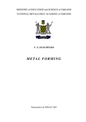
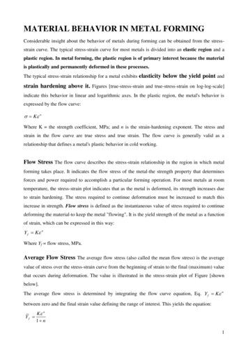
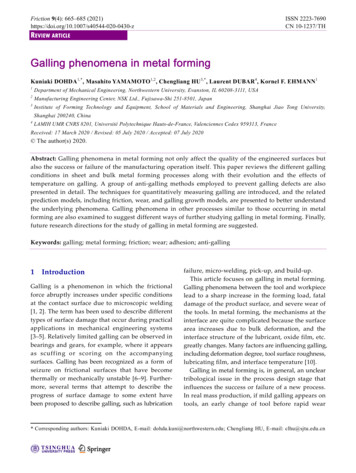
Metal forming processesMetal forming: Large set of manufacturing processes in which the material is deformedplastically to take the shape of the die geometry. The tools used for such deformationare called die, punch etc. depending on the type of process.Plastic deformation: Stresses beyond yield strength of the workpiece material isrequired.Categories: Bulk metal forming, Sheet metal formingstretchingGeneral classification of metal forming processesGanesh Narayanan,IITGM.P. Groover,R.Fundamentalof modern manufacturingMaterials, Processes and systems, 4ed
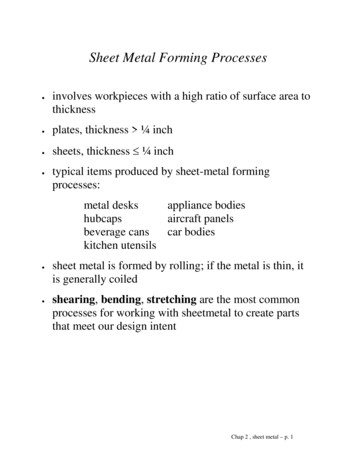
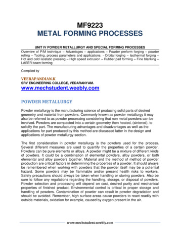
Classification of basic bulk forming processesForgingRollingExtrusionWire drawingBulk forming: It is a severe deformation process resulting in massive shape change. Thesurface area-to-volume of the work is relatively small. Mostly done in hot working conditions.Rolling: In this process, the workpiece in the form of slab or plate is compressed between tworotating rolls in the thickness direction, so that the thickness is reduced. The rotating rolls drawthe slab into the gap and compresses it. The final product is in the form of sheet.Forging: The workpiece is compressed between two dies containing shaped contours. The dieshapes are imparted into the final part.Extrusion: In this, the workpiece is compressed or pushed into the die opening to take theshape of the die hole as its cross section.Wire or rod drawing: similar to extrusion, except that the workpiece is pulled through the dieopening to take the cross-section. R. Ganesh Narayanan, IITG
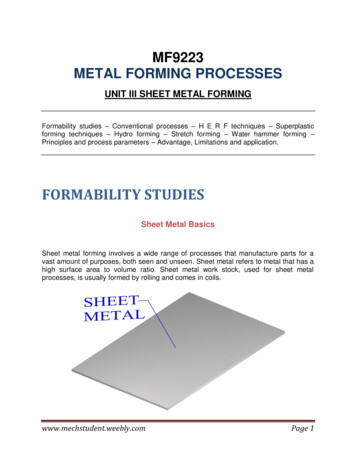
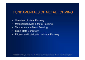
Classification of basic sheet forming processesBendingDeep drawingshearingSheet forming: Sheet metal forming involves forming and cutting operations performed on metalsheets, strips, and coils. The surface area-to-volume ratio of the starting metal is relatively high.Tools include punch, die that are used to deform the sheets.Bending: In this, the sheet material is strained by punch to give a bend shape (angle shape)usually in a straight axis.Deep (or cup) drawing: In this operation, forming of a flat metal sheet into a hollow or concaveshape like a cup, is performed by stretching the metal in some regions. A blank-holder is used toclamp the blank on the die, while the punch pushes into the sheet metal. The sheet is drawn intothe die hole taking the shape of the cavity.Shearing: This is nothing but cutting of sheets by shearing action.R. Ganesh Narayanan, IITG
Cold working, warm working, hot workingCold working: Generally done at room temperature or slightly above RT.Advantages compared to hot forming:(1) closer tolerances can be achieved; (2) good surface finish; (3) because of strainhardening, higher strength and hardness is seen in part; (4) grain flow duringdeformation provides the opportunity for desirable directional properties; (5) since noheating of the work is involved, furnace, fuel, electricity costs are minimized, (6)Machining requirements are minimum resulting in possibility of near net shapedforming.Disadvantages: (1) higher forces and power are required; (2) strain hardening of thework metal limit the amount of forming that can be done, (3) sometimes cold formingannealing-cold forming cycle should be followed, (4) the work piece is not ductileenough to be cold worked.Warm working: In this case, forming is performed at temperatures just above roomtemperature but below the recrystallization temperature. The working temperature istaken to be 0.3 Tm where Tm is the melting point of the workpiece.Advantages: (1) enhanced plastic deformation properties, (2) lower forces required, (3)intricate work geometries possible, (4) annealing stages can be reduced.R. Ganesh Narayanan, IITG
Hot working: Involves deformation above recrystallization temperature,between 0.5Tm to 0.75Tm.Advantages: (1) significant plastic deformation can be given to the sample,(2) significant change in workpiece shape, (3) lower forces are required, (4)materials with premature failure can be hot formed, (5) absence ofstrengthening due to work hardening.Disadvantages: (1) shorter tool life, (2) poor surface finish, (3) lowerdimensional accuracy, (4) sample surface oxidationR. Ganesh Narayanan, IITG
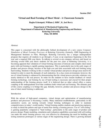
Bulk forming processesForging It is a deformation process in which the work piece is compressed between twodies, using either impact load or hydraulic load (or gradual load) to deform it. It is used to make a variety of high-strength components for automotive, aerospace,and other applications. The components include engine crankshafts, connecting rods,gears, aircraft structural components, jet engine turbine parts etc. Category based on temperature : cold, warm, hot forging Category based on presses:impact load forging hammer; gradual pressure forging press Category based on type of forming:Open die forging, impression die forging, flashless forgingIn open die forging, the work piece iscompressed between two flat platens or dies,thus allowing the metal to flow without anyrestriction in the sideward direction relative tothe die surfaces.Open die forgingR. Ganesh Narayanan, IITGM.P. Groover, Fundamental of modern manufacturing Materials, Processes and systems, 4ed
impression die forgingflashless forgingIn impression die forging, the die surfaces contain a shape that is given to the workpiece during compression, thus restricting the metal flow significantly. There is someextra deformed material outside the die impression which is called as flash. This willbe trimmed off later.In flashless forging, the work piece is fully restricted within the die and no flash isproduced. The amount of initial work piece used must be controlled accurately sothat it matches the volume of the die cavity.R. Ganesh Narayanan, IITG
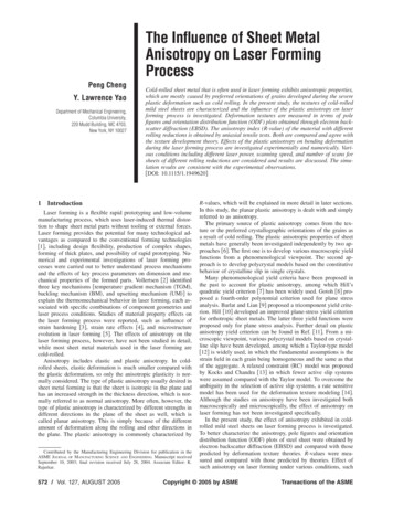
Open die forgingA simplest example of open die forging is compression of billet between two flat diehalves which is like compression test. This also known as upsetting or upset forging.Basically height decreases and diameter increases.Under ideal conditions, where there is no friction between the billet and die surfaces,homogeneous deformation occurs. In this, the diameter increases uniformlythroughout its height.In ideal condition, ε ln (ho/h). h will be equal to hf at the end of compression, ε willbe maximum for the whole forming. Also F σf A is used to find the force required forforging, where σf is the flow stress corresponding to ε at that stage of forming.Start of compressionPartial compressionR. Ganesh Narayanan, IITGCompleted compressionM.P. Groover, Fundamental of modern manufacturing Materials, Processes and systems, 4ed
In actual forging operation, the deformation will not be homogeneous asbulging occurs because of the presence of friction at the die-billet interface.This friction opposes the movement of billet at the surface. This is calledbarreling effect.The barreling effect will be significant as the diameter-to-height (D/h) ratio ofthe workpart increases, due to the greater contact area at the billet–dieinterface. Temperature will also affect the barreling phenomenon.Start nIn actual forging, the accurate force evaluation is done by using, F Kf σf A byconsidering the effect of friction and D/h ratio. Here,0.4 DK f 1 hWhere Kf forging shape factor, μ coefficient of friction, D work piece diameter, h workR. Ganesh Narayanan, IITGpiece height
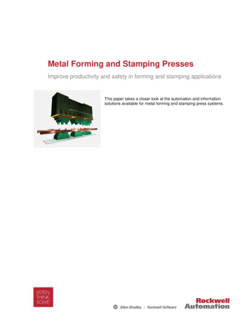
Typical load-stroke curvein open die forgingEffect of D/h ratio on load:Compression Loadµ2 µ1µ2µ1µ0D/hEffect of h/D ratio on barreling:Long cylinder: h/D 2Cylinder having h/D 2R. GaneshNarayanan, IITGwithfrictionFrictionless compression
Closed die forgingClosed die forging called as impression die forging is performed in dies which has theimpression that will be imparted to the work piece through forming.In the intermediate stage, the initial billet deforms partially giving a bulged shape.During the die full closure, impression is fully filled with deformed billet and furthermoves out of the impression to form flash.In multi stage operation, separate die cavities are required for shape change. In theinitial stages, uniform distribution of properties and microstructure are seen. In the finalstage, actual shape modification is observed. When drop forging is used, several blowsof the hammer may be required for each step.Starting stageIntermediateFinal stage withstageflash formationR. Ganesh Narayanan, IITGM.P. Groover, Fundamental of modern manufacturing Materials, Processes and systems, 4ed
The formula used for open die forging earlier can be used for closed dieforging, i.e.,F Kf σf AWhere F is maximum force in the operation; A is projected area of the partincluding flash, σf is flow stress of the material, Kf is forging shape factor.Now selecting the proper value of flow stress is difficult because the strainvaries throughout the work piece for complex shapes and hence thestrength varies. Sometimes an average strength is used. Kf is used fortaking care of different shapes of parts. Table shows the typical values of Kfused for force calculation. In hot working, appropriate flow stress at thattemperature is used.The above equation is applied to find the maximum force during theoperation, since this is the load that will determine the required capacity ofthe press used in the forging operation.R. Ganesh Narayanan, IITG
Impression die forging is not capable of making close tolerance objects.Machining is generally required to achieve the accuracies needed. The basicgeometry of the part is obtained from the forging process, with subsequentmachining done on those portions of the part that require precision finishinglike holes, threads etc.In order to improve the efficiency of closed die forging, precision forging wasdeveloped that can produce forgings with thin sections, more complexgeometries, closer tolerances, and elimination of machining allowances. Inprecision forging operations, sometimes machining is fully eliminated which iscalled near-net shape forging.R. Ganesh Narayanan, IITG
Flashless forgingThe three stages of flashless forging is shown below:In flashless forging, most important is that the work piece volume mustequal the space in the die cavity within a very close tolerance.If the starting billet size is too large, excessive pressures will cause damageto the die and press.If the billet size is too small, the cavity will not be filled.Because of the demands, this process is suitable to make simple andsymmetrical part geometries, and to work materials such as Al, Mg and theiralloys.R. Ganesh Narayanan, IITGM.P. Groover, Fundamental of modern manufacturing Materials, Processes and systems, 4ed
Coining is a simple application of closed die forging in which fine details in thedie impression are impressed into the top or/and bottom surfaces of the workpiece.Though there is little flow of metal in coining, the pressures required toreproduce the surface details in the die cavity are at par with other impressionforging operations.Starting of cycleFully compressedR. MakingGanesh Narayanan,of coin IITGRam pressureremoved andejection of part
Forging hammers, presses and diesHammers:Hammers operate by applying an impact loading on the work piece. This isalso called as drop hammer, owing to the means of delivering impact energy.When the upper die strikes the work piece, theimpact energy applied causes the part to takethe form of the die cavity. Sometimes, severalblows of the hammer are required to achievethe desired change in shape.Drop hammers are classified as:Gravity drop hammers, power drop hammers.Gravity drop hammers - achieve their energyby the falling weight of a heavy ram. The forceof the blow is dependent on the height of thedrop and the weight of the ram.Power drop hammers - accelerate the ram byR. Ganesh Narayanan, IITGpressurized air or steam.Drop hammers
Presses:The force is given to the forging billet gradually, and not like impact force.Mechanical presses: In these presses, the rotating motion of a drive motoris converted into the translation motion of the ram. They operate by meansof eccentrics, cranks, or knuckle joints. Mechanical presses typicallyachieve very high forces at the bottom of the forging stroke.Hydraulic presses : hydraulically driven piston is used to actuate the ram.Screw presses : apply force by a screw mechanism that drives the verticalram. Both screw drive and hydraulic drive operate at relatively low ramspeeds.Forging dies:R. Ganesh Narayanan, IITGM.P. Groover, Fundamental of modern manufacturing Materials, Processes and systems, 4ed
Parting line: The parting line divides the upper die from the lower die. In otherwords, it is the plane where the two die halves meet. The selection of partingline affects grain flow in the part, required load, and flash formation.Draft: It is the amount of taper given on the sides of the part required toremove it from the die.Draft angles: It is meant for easy removal of part after operation is completed.3 for Al and Mg parts; 5 to 7 for steel parts.Webs and ribs: They are thin portions of the forging that is parallel andperpendicular to the parting line. More difficulty is witnessed in forming thepart as they become thinner.Fillet and corner radii: Small radii limits the metal flow and increase stresseson die surfaces during forging.Flash: The pressure build up because of flash formation is controlled properdesign of gutter and flash land.R. Ganesh Narayanan, IITG
Other forging operationsUpset forging:It is a deformation operation in which a cylindrical work piece is increased in diameterwith reduction in length. In industry practice, it is done as closed die forging.Upset forging is widely used in the fastener industries to form heads on nails, bolts,and similar products.Feeding of work pieceGripping of work piece and retracting of stopForward movement ofpunch and upsettingForging operation completesR. Ganesh Narayanan, IITGM.P. Groover, Fundamental of modern manufacturing Materials, Processes and systems, 4ed
Heading:The following figure shows variety of heading operations with different dieprofiles.Heading a die using open die forgingRound head formed by punch onlyHead formed inside die onlyBolt head formed by bothdie and punchLong bar stock (work piece) is fed into the machines by horizontal slides, the end ofthe stock is upset forged, and the piece is cut to appropriate length to make thedesired product. The maximum length that can be upset in a single blow is threetimes the diameter of the initial wire stock.R. Ganesh Narayanan, IITG
Swaging:Swaging is used to reduce the diameter of a tube or a rod at the end of thework piece to create a tapered section. In general, this process is conductedby means of rotating dies that hammer a workpiece in radial direction inwardto taper it as the piece is fed into the dies. A mandrel is required to control theshape and size of the internal diameter of tubular parts during swaging.SwagingDiameter reduction of solid workRadial forging:This operation is same as swaging,except that in radial forging, the dies donot rotate around the work piece,instead, the work is rotated as it feedsinto the hammering dies.Tube taperingSwaging to form a groove onthe tubeSwaging with different die profilesSwaging the edge of a cylinderR. Ganesh Narayanan, IITG
Roll forging:It is a forming process used to reduce the cross section of a cylindrical orrectangular rod by passing it through a set of opposing rolls that have matchinggrooves w.r.t. the desired shape of the final part. It combines both rolling andforging, but classified as forging operation.Depending on the amount of deformation, the rolls rotate partially. Roll-forgedparts are generally stronger and possess desired grain structure compared tomachining that might be used to produce the same part.R. Ganesh Narayanan, IITG
Orbital forging:In this process, forming is imparted to the workpiece by means of a coneshaped upper die that is simultaneously rolled and pressed into the work.The work is supported on a lower die.Because of the inclined axis of cone, only a small area of the work surface iscompressed at any stage of forming. As the upper die revolves, the areaunder compression also revolves. Because of partial deformation contact atany stage of forming, there is a substantial reduction in press loadrequirement.R. Ganesh Narayanan, IITG
Isothermal forging:It is a hot-forging operation in which the work is maintained at someelevated temperature during forming. The forging dies are also maintainedat the same elevated temperature. By avoiding chill of the work in contactwith the cold die surfaces, the metal flows more readily and the forcerequirement is reduced.The process is expensive than conventional forging and is usually meant fordifficult-to-forge metals, like Ti, superalloys, and for complex part shapes.The process is done in vacuum or inert atmosphere to avoid rapid oxidationof the die material.R. Ganesh Narayanan, IITG
ExtrusionExtrusion is a bulk forming process in which the work metal is forced orcompressed to flow through a die hole to produce a desired cross-sectionalshape. Example: squeezing toothpaste from a toothpaste tube.Advantages :- Variety of shapes are possible, especially using hot extrusion- Grain structure and strength properties are enhanced in cold and warmextrusion- Close tolerances are possible, mainly in cold extrusionTypes of extrusion:Direct or forward extrusion, Indirect or backward extrusionDirect extrusion: - A metal billet is first loaded into a container having dieholes. A ram compresses the material, forcing it to flow through the die holes.- Some extra portion of the billet will be present at the end of the process thatcannot be extruded and is called butt. It is separated from the product byR. GaneshNarayanan, IITGcutting it just beyond the exit ofthe die.
Direct extrusion- In direct extrusion, a significant amount of friction exists between the billetsurface and the container walls, as the billet is forced to slide toward the dieopening. Because of the presence of friction, a substantial increase in the ramforce is required.- In hot direct extrusion, the friction problem is increased by the presence ofoxide layer on the surface of the billet. This oxide layer can cause defects inthe extruded product.- In order to address these problems, a dummy block is used between the ramand the work billet. The diameter of the dummy block is kept slightly smallerthan the billet diameter, so that a thin layer of billet containing the oxide layer isleft in the container, leaving the final product free of oxides.R. Ganesh Narayanan, IITGM.P. Groover, Fundamental of modern manufacturing Materials, Processes and systems, 4ed
Making hollow shapes using directextrusionHollow sections like tubes can be made using direct extrusion setup shown inabove figure. The starting billet is prepared with a hole parallel to its axis. Asthe billet is compressed, the material will flow through the gap between themandrel and the die opening.Indirect extrusion: - In this type, the die is mounted to the ram and not on thecontainer. As the ram compresses the metal, it flows through the die hole onthe ram side which is in opposite direction to the movement of ram.- Since there is no relative motion between the billet and the container, there isno friction at the interface, and hence the ram force is lower than in directextrusion.- Limitations: lower rigidity of the hollow ram, difficulty in supporting theextruded product at the exit R. Ganesh Narayanan, IITG
Indirect extrusion: solid billet and hollow billetSimple analysis of extrusionPressure distributionand billet dimensions in direct extrusionR. Ganesh Narayanan, IITG
Assuming the initial billet and extrudate are in round cross-section. Animportant parameter, extrusion ratio (re), is defined as below:A0re AfA0 - CSA of the initial billetAf - CSA of the extruded sectionTrue strain in extrusion under ideal deformation (no friction and redundantwork) is given by,A0 ln( re ) ln( )AfUnder ideal deformation, the ram pressure required to extrude the billetthrough die hole is given by,A0K np Y f ln( re ) Y f ln( ) where Y f 1 nAfWhere Yf is average flow stress, andextrusion process.Note: The average flow stress is found outby integrating the flow curve equationbetween zero and the final strain definingthe range of forming is maximum strain value during theThe actual pressure for extrusion will be greater than in ideal case, becauseof the friction between billet and die and billet and container wall.R. Ganesh Narayanan, IITG
There are various equations used to evaluate the actual true strain andassociated ram pressure during extrusion. The following relation proposedby Johnson is of great interest. x a b ln re a b p Yf xWhere x is extrusion strain; a and b are empirical constants for a given dieangle. Typical values are: a 0.8, b 1.2 - 1.5.In direct extrusion, assuming that friction exists at the interface, we can findthe actual extrusion pressure as follows:billet-container friction force additional ram force to overcome thatfriction pe D0 L p f D042Where pf is additional pressurerequired to overcome friction, pe ispressure against the container wallThe above eqn. assume sliding friction condition. Assuming sticking friction at theinterface, we can write:p f D0 2Where K is shear yield strength & m 1K D0 L 4
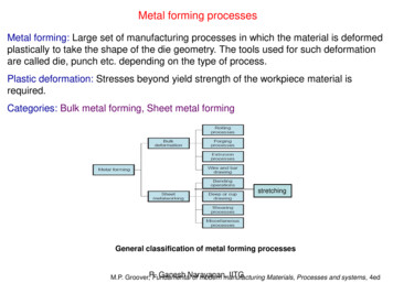
The above eqn. gives,Assuming,K Yf2pf 4 KLD0we get, p f Y f2LD0This is the additional pressure required toovercome friction during extrusion.Now the actual ram pressure required fordirect extrusion is given by,2L p Y f x D0 The shape of the initial pressure build updepends on die angle. Higher die anglescause steeper pressure buildups.L is the billet length remaining to be extruded,and D0 is the initial diameter of the billet. Herep is reduced as the remaining billet lengthdecreases during the extrusion process.Ram pressure variation with stroke for directand indirect extrusion is shown in Figure.R. Ganesh Narayanan, IITGM.P. Groover, Fundamental of modern manufacturing Materials, Processes and systems, 4ed
Sliding friction pSticking friction mKR. Ganesh Narayanan, IITGp
A billet 75 mm long and 25 mm in diameter is to be extruded in a directextrusion operation with extrusion ratio re 4.0. The extrudate has a roundcross section. The die angle (half angle) is 90 . The work metal has astrength coefficient of 415 MPa, and strain-hardening exponent of 0.18.Use the Johnson formula with a 0.8 and b 1.5 to estimate extrusion strain.Find the pressure applied to the end of the billet as the ram moves forward.R. Ganesh Narayanan, IITG
Empirical formulae for extrusion pressureHot extrusion of Al alloys:For extrusion of pure Al, Al-Zn alloy, Al-Zn-Mg alloy in the temperature range of 50500 C.pe / 0 0.52 1.32 ln RHere R 1/(1-r)where ‘r’ is therelative reductionfor values of R from 100 to 1000 in areafor values of R from 1 to 100pe / 0 13 4.78 ln RCold extrusion of steel:pe 0.262 F ( Ar )0.787(2 )0.375Nmm2Where Ar percent reduction in area F A1 A2 100A1Yield strength of steelYield strength of leadR. Ganesh Narayanan, IITGB.L.Juneja, Fundamental of metal forming processes,2ed
Extrusion dies- Two important factors in an extrusion die are: die angle, orifice shape.- For low die angles, surface area of the die is large, resulting in increasedfriction at the die-billet interface. Higher friction results in higher ram force.- For a large die angle, more turbulence in the metal flow is caused duringreduction, increasing the ram force required.- The effect of die angle on ram force is a U-shaped function, shown inFigure. So, an optimum die angle exists. The optimum angle depends onvarious factors like work material, billet temperature, and lubrication.R. Ganesh Narayanan, IITG
- The extrusion pressure eqns. derived earlier are for a circular die orifice.- The shape of the die orifice affects the ram pressure required to perform anextrusion operation, as it determines the amount of squeezing of metal billet.-The effect of the die orifice shape can be assessed by the die shape factor,defined as the ratio of the pressure required to extrude a cross section of agiven shape relative to the extrusion pressure for a circular cross section ofthe same area. cx k x 0.98 0.02 cc 2.25Where kx is the die shape factor in extrusion; Cx is the perimeter of theextruded cross section, and Cc is the perimeter of a circle of the same area asthe actual extruded shape.cxvaries from 1 to 6.ccR. Ganesh Narayanan, IITGM.P. Groover, Fundamental of modern manufacturing Materials, Processes and systems, 4ed
Die materialsFor hot extrusion - tool and alloy steels.Important properties of die materials are high wear resistance, high thermalconductivity to remove heat from the process.For cold extrusion - tool steels and cemented carbides.Carbides are used when high production rates, long die life, and gooddimensional control are expected.R. Ganesh Narayanan, IITG
Other extrusion processesImpact extrusion:- It is performed at higher speeds and shorter strokes. The billet is extrudedthrough the die by impact pressure and not just by applying pressure.- But impacting can be carried out as forward extrusion, backward extrusion,or combination of these.forward extrusionBackward extrusionR. Ganesh Narayanan, IITG combined extrusion
- Impact extrusion is carried out as cold forming. Very thin walls are possibleby backward impact extrusion method. Eg: making tooth paste tubes,battery cases.- Advantages of IE: large reductions and high production ratesHydrostatic extrusion:Hydrostatic extrusionR. Ganesh Narayanan, IITGM.P. Groover, Fundamental of modern manufacturing Materials, Processes and systems, 4ed
In hydrostatic extrusion, the billet is surrounded with fluid inside thecontainer and the fluid is pressurized by the forward motion of the ram.There is no friction inside the container because of the fluid, and friction isminimized at the die opening. If used at high temperatures, special fluidsand procedures must be followed.Hydrostatic pressure on the work and no friction situation increases thematerial’s ductility. Hence this process can be used on metals that wouldbe too brittle for conventional extrusion methods.This process is also applicable for ductile metals, and here high reductionratios are possible.The preparation of starting work billet is important. The billet must beformed with a taper at one end to fit tightly into the die entry angle, so thatit acts as a seal to prevent fluid leakage through die hole under pressure.R. Ganesh Narayanan, IITG
Defects during extrusionCenterburst:- This is an internal crack that develops as a result of tensilestresses along the center axis of the workpiece duringextrusion. A large material motion at the outer regions pullsthe material along the center of the work. Beyond a criticallimit, bursting occurs.- Conditions that promote this defect are: higher die angles,low extrusion ratios, and impurities in the work metal. This isalso called as Chevron cracking.CenterburstPiping: It is the formation of a sink hole in the end of thebillet. This is minimized by the usage of a dummy blockwhose diameter is slightly less than that of the billet.PipingSurface cracking: This defect results from high workpiecetemperatures that cause cracks to develop at the surface.They also occur at higher extrusion speeds, leading to highstrain rates and heat generation. Higher friction at thesurface and surface chilling of high temperature billets in hotextrusion also cause this defect.Surface crackingR. Ganesh Narayanan, IITG
Wire, rod, bar drawing- In this bulk forming process, a wire, rod, bar are pulled through a die holereducing their cross-section area.Wire, rod, bar drawingDifference between wire drawing and rod drawing:Initial stock size:- The basic difference between bar drawing and wire drawing is the stock sizethat is used for forming. Bar drawing is meant for large diameter bar and rod,while wire drawing is meant for small diameter stock. Wire sizes of the orderof 0.03 mm are produced in wire drawing.R. Ganesh Narayanan, IITG
Operating stages:- Bar drawing is generally done as a single stage operation, in which stockis pulled through one die opening. The inlet bars are straight and not in theform of coil, which limits the length of the work that can be drawn. Thisnecessitates a batch type operation.- In contrast, wire is drawn from coils consisting of several hundred metersof wire and is drawn through a series of dies. The number of dies variesbetween 4 and 12. This is termed as ‘continuous drawing’ because of thelong production runs that are achieved with the wire coils. The segmentscan be butt-welded to the next to make the operation truly continuous.R. Ganesh Narayanan, IITG
Simple analysis of wire drawingTrue strain in wire drawing under ideal deformation (no friction and redundant work)is given by, ln(A01) ln()Af1 rHere r (A0 – Af) / A0Under ideal deformation, the stress required in wire drawing is given by,A d Y f ln( 0 )AfK nHere Y f ,Y f is the average flow stress1 ncorresponding to ε mentioned in above equation.In order to consider the effect of die angle and friction coefficient on the drawingstress, Schey has proposed another equation as shown below: d Y f 1 A ln( 0 )tan AfR. Ganesh Narayanan, IITG
Here is a term that accounts for inhomogeneous deformation which is foundby the following eqn. for round cross-section. 0.88 0.12DLcHere D is the average diameter of the workpiece, LC is thecontact length of the work with die given by,D D0 D f2; LC D0 D f2 sin Finally the drawing force is given by, F AfσdThe power required for drawing is givenby multiplying drawing force with exitvelocity of the w
Sheet forming: Sheet metal forming involves forming and cutting operations performed on metal sheets, strips, and coils. The surface area-to-volume ratio of the starting metal is relatively high. Tools include punch, die that are used to deform the sheets. Classification of basic sheet