Transcription
1Designof FormingChesterJ. VanColoradoSchoolI.BULKProcesses:BulkTyneof Mines,Golden,Colorado,U.S.A.DEFORMATIONBulk defonnation is a metal-fonning process where thedefonnation is three-dimensional in nature. The primary use of the tenn bulk deformation is to distinguish itfrom sheet-fonning processes. In sheet-forming operations, the defonnation stressesare usually in the plane ofthe sheet metal, whereas in bulk defonnation, thedefonnation stresses possess components in all threecoordinate directions. Bulk defonnation includes metalworking processes such as forging, extrusion, rolling,and drawing.II. CLASSIFICATIONPROCESSESOF DEFORMATIONThe classification of deformation processescan be donein one of several ways. The more common classificationschemesare based on temperature, flow behavior, andstressstate. The temperature of the deformation processis under direct control of the operator and has aprofound effect on the viability of the process and theresulting shape and microstructure of the finished product. The flow behavior and the stress state differ fromtemperature in that they are a result of the actualdeformation process that one chooses.A. TemperatureClassificationThe temperature classification scheme is normally divided into two primary regions-cold working and hotworking. Cold working occurs at relatively low temper-jFormingatures relative to the melting point of the metal. Hotworking occurs at temperatures above tJllerecrystallization temperature of the metal. There is a third temperature range, warm working, which is being criticallyexamined due to energy savings and is, in some cases,used by industries.1. Cold Working TemperaturesCold working usually refers to metal deformation that iscarried out at room temperature. Th, phenomenonassociated with cold work occurs wht:n the metal isdeformed at temperatures that are about 30% or less ofits melting temperature on an absolute temperaturescale. During cold work, the metal , xperiences anincreased number of dislocations and elltanglement ofthese dislocations, causing strain hardening. With strainhardening, the strength of the metal increases withdeformation. To recrystallize the metal, ;i thermal treatment, called an anneal, is often needed. During annealing, the strength of the metal can be drastically reducedwith a significant increase in ductility. The ductilityincrease often allows further deformation to occurbefore fracture. The final surface finish alld dimensionaltolerances can be well controlled in a cold work process.2. Hot Working TemperaturesHot working l;)CCursat temperatures of 61 %or above ofthe melting temperature of the metal on an absolutescale. At elevated temperatures, the metal has decreasedstrength, hence the forces needed for deformation arereduced. Recrystallization occurs readily, causing newgrains to continually form during deformation. The
2Van Tynecontinual formation of new grains causesthe ductility ofthe metal to remain high, allowing large amounts ofdeformation to be imparted without fracture. Controlof final dimensions is more difficult in a hot-workedmetal due to scale formation and volumetrical changesin the part during subsequent cooling.analysis can be applied. For a continuous-flow process,a more complex analysis needsto be used to simulate theprocess accurately. The complex analysis needs to account for the continually changing shape of the deformation region.C.3.Warm working occurs between hot working and coldworking. It occurs in the approximate temperaturerange of 30-60% of the melting temperature of the metalon an absolute scale. The forces required to deformmetal in the warm working regime are higher than during hot working. The final finish and dimensional tolerancesare better than hot working but not nearly as goodas a cold working process. Although warm work seemsto have drawbacks, the primary driver for warm working is economic. There is significant cost in heating ametal up to hot working temperatures. If the workingtemperature is lowered, there can be major cost savingsin the process.B.StressStateClassificationWarm Working TemperaturesFlow BehaviorClassificationThe flow behavior of a metal or alloy during bulk deformation processes falls into one of two categoriescontinuous flow or quasi-static. The easiest way to distinguish between these two types of flow is to imagine amovie being made of the deformation region duringprocessing. If the shape of the deformation regionchanges during each frame of the movie, the process isa continuous-flow process. If in each frame of the moviethe shape of the deformation region remains the same,even though a different material is in the region, it is aquasi-static-flow process. The bulk deformation processof forging is an example of a continuous-flow process.As the metal is being shaped in the forging die cavity, thedeforming region, which is often the entire amount ofmetal, is continuously undergoing change. Processessuch as rolling, wire drawing, and extrusion are examples of quasi-static flow. For example, in rolling, thedeformation region is the metal being squeezedbetweentwo rolls. The shape of the deformation region does notvary , aside from initial startup and final finish, althoughdifferent material flows into and out of the region.The classification based on flow is useful in determining what type of modeling scheme can be used tosimulate the bulk deformation process. For a quasi-static-flow process, the deformation region can often behandled as a single region and a steady-state type ofIn all bulk deformation processes, the primary deformation stress is compressive in nature. This is in contrast to sheet metal forming where 1:ensilestresses areoften used. Stress state classification consists of twocategories for bulk deformation-directcompressionand indirect compression. In direct compression, thetools or dies directly squeeze the workpiece. Forging,extrusion, and rolling are examples of direct compression processes. In indirect compression, the deformation region of the workpiece is in a \;ompressive stressstate but the application of these compressive stressesoccurs by indirect means. Wire drawing is an example ofan indirect compression process, where the wire is pulledthrough a die. The workpiece conta(;ts the convergingsurfaces of the dies, creating high forces normal to thedie surface. The dies react to these J[orcesby pushingback on the workpiece, causing a compressive stressstate to exist in the deforming region of the metal. Thusalthough the equipment action is of a tensile (pulling)nature, the plastic deforming region is being squeezed.It should be noted that although the stress state forbulk deformation is compressive, there are situationswhere tensile stress components may be present withinthe workpiece and fracture may o.ccur. The metalforming engineer needs to be aware of these types ofsituations and to properly design the' process to avoidthe potential fracturing that can occur on the workpiecedue to the tensile stresscomponents. For example, in theforging of a right circular cylinder between two flat diesin the axial direction, if friction on the top and bottomsurfaces is high, the sides of the cylinder will bulge andsome tensile hoop stress may occur on the outsidesurface of the workpiece. A more insidious example isan extrusion process where a small reduction is performed through a die with a high diie angle. For thissituation, the deformation region ma ' be limited to thesurface region of the workpiece, causing some internaltensile stress components along the centerline of theworkpiece. If the internal tensile stress componentsbecome excessively high, they can (;ause an internalfracture in the workpiece. This fracture is referred toas central burst. The worst aspect of central burst is thatit cannot be detected via visual methods.
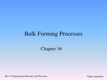
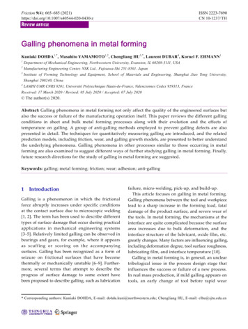
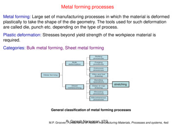
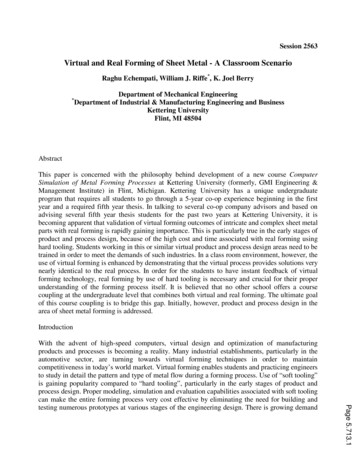
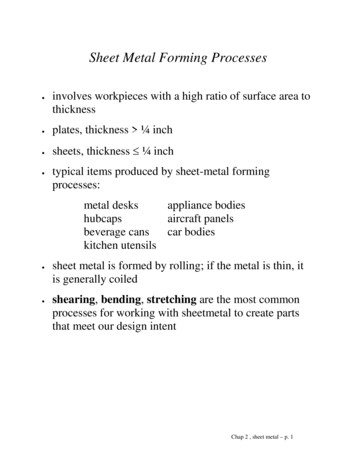
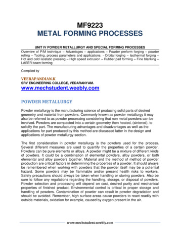
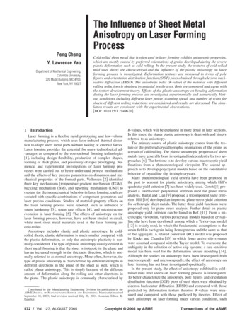
Design of Forming Processes: Bulk FormingIII. TYPES OF BULK DEFORMATIONPROCESSESA.e)b)c)a)b),:)ForgingForging is a metalworking process where a workpiece isshaped by compressive forces using various dies andtools. The forging process produces discrete parts. Somefinishing operations are usually required. Similarlyshaped parts can often be produced by casting or powder metallurgy operations, but the mechanical properties of a forged component are usually superiorcompared to other processing methods. Forging canbe done hot or cold. Warm forging is a process that isa)3I)g)d)h)Figure 1 Examples of forged parts: (a) automotive crankshaft; (b) truck axle; (c) truck bracket; (d) universal joint; (e)automotive gears; (f) truck assembly part; (g) couplingfittings; and (h) hammer head. (From Ref. I.) Figure 2 Open die forging tools: (a) fiat dies; (b) U-shapeddies; and (c) V-shaped dies. (From Ref. 2.)growing in popularity due primarily to thermal energycosts. Typical forged parts are shown in Fig. I.Open die forging consists of dies ,vith very simplegeometry. The dies are usually flat, U-shaped, or vshaped, as seen in Fig. 2. The shaping of the metaloccurs through manipulation of the workpiece and skillof the operator. Itisa process that is usi:ful in producinga small number of pieces. It is difficult to hold to closetolerance in this type of forging. Open die forging between two flat dies is often called upsetting. Cogging ordrawing out is an open die forging process where thethickness of the workpiece is reduced by successivesmall strikes along the length of the :metal. Open dieforging is closely related to blacksmithing.Closed die or impression die forging consists of a dieset with a machined impression, as shown in Fig. 3.There is good use of metal in this operation as comparedto open die forging. Excessmetal beyond the size neededfor forging is used and flows into the :utter portion ofthe die set to produce flash. The excess metal helps toinsure that the cavities are completely filled at the end ofthe press stroke. Good tolerances and accuracy of thefinal forging are attainable. The die CO!;tsfor closed dieforging are fairly high due to their property requirements and machining costs.Closed die forging often occurs in a s( quenceof steps.Each step of the operation usually has its own impression in the die block. The first step distributes metalsinto regions where extra volume is required in the finalcomponent. This step often involves ed!:ing, where extrametal is gathered, or fullering, where metal is movedaway from the local region. In hot forgiDg, the first stepis r ferred to as busting because the scale on the surfaceof the workpiece is busted off. The second step isblocking, where the part is formed into a rough shape.The third step is finishing, where the final shape of thecomponent is imparted to the workpiece. The fourthstep is trimming, where the excess m( tal in the flashregion is trimmed from the componenl:. Figure 3 illustrates these various steps.
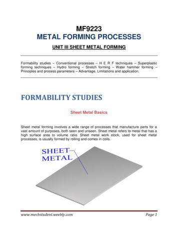
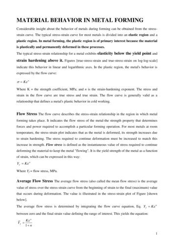
4Van TyneFinishedProductFigure 3 Impression forging dies with forging sequence.(From Ref. 3.)Mechanical presses are stroke-limited equipment witha large flywheel powered by an electril;al motor. The upand-down motion of the ram is handled via a connectingrod attached to a crank shaft. The tra,'el distance duringeach press stroke is controlled by machine design andoperation. Hydraulic presses are load-limited equipment where the press will stop once ilts load capacity isreached. The power comes from pressurized hydraulicfluid. Screw presses, similar to haIDJners, are energylimited equipment. A large flywheel transmits powerthrough a vertical screw, which causesthe ram to move.The ram movement stops when all tht energy from theflywheel has dissipated. Table 2 provides some numerical details about hydraulic pressesto produce the samegear blank as in Table 1.In order to be successful in forging a metal, theformability of the metal needs to be understood, especially with regard to temperature and speed. The impression die shape needs to be carefully designed andmachined to allow a good flow of metal without seamsor laps developing. The die material needs to be carefully chosen to match the metal bein : shaped and thetemperature of the operation.B.The machines used for forging are hammers andpresses. Hammers are energy-Iimited equipment andcan be a simple gravity drop machine where a freefalling ram strikes the workpiece. Augmentation of theenergy supplied to the hammer can be done in the formof pressured air, steam or hydraulic fluid. In a hot closeddie operation, multiple blows are usually needed duringeach step, especially the blocking and finishing steps,when using a hammer to forge metal. Table I providessome numerical details about hammers for a typicalgear blank forging.For forging, there are three types of presses usedmechanical press, hydraulic press, and screw press.Table 1ExtrusionExtrusion is a bulk deformation proce s where a billet,generally cylindrical, is placed in a chamber and forcedthrough a die. The die opening can be round to producea cylindrical product, or the opening Ln have a varietyof shapes. Typical extrusion products are shown inFig. 4. Because of the large reductions imparted duringthe extrusion process, most extrusioll processes areperformed hot in order to reduce the flow strength ofthe metal. Cold extrusion can occur but it is usually onestep in a multistep cold forging operation.Forward or direct extrusion is where the billet ispushed from the backside and the front side flowsCharacteristics of Hammers for Forging a 4.45-lb Steel Gear Blank
Design of FormingProcesses:Bulk Forming5Two-hundred-fifty-tonpress stalled and left underfilled on outer diameter.Fast 2000-ton press is similar to mechanical or screw press.Smaller presses resulted in increased die temperature.Source: Ref. 4.through the die. Indirect or inverse or backward extrusion is where the die, which imparts shape, moves intothe billet. The equipment used to perform an indirectextrusion is more complex than for a forward extrusion.To overcome the significant friction resistance betweenthe billet and the chamber in a forward extrusion,hydrostatic extrusion has been developed. In hydrostatic extrusion, the billet is smaller than the chamber and issurrounded by hydraulic fluid. The hydraulic fluid ispressurized, which squeezes the billet through the dieopening. Caution with both the sealing of the fluid andat the end of the process, where the final part of the billetcould become a high-velocity projectile, needs to beexerted. Impact extrusion is similar to indirect extrusionand is often performed cold. The tooling, usually a solidpunch, moves rapidly into the workpiece, causing it toflow backward and around the face of the punch. Thisproduces a tubular-shaped type of product. These typesof extrusions are schematically shown in Fig. 5.The equipment for extrusion is normally a horizontalhydraulic press. A large shape change is imparted to thebillet during a single stroke of the press. The sha change causes significant distortion in the metal duringthe deformation.For successin extrusion, the temperature and speedof the process need to be determined based on theFigure4Examplesof extrudedparts. (FromRef. 5.formability of the metal being deformed. Excessivetemperature, speed, or friction can cause surface cracksto propagate along grain boundaries, wJlich are referredto as fir tree cracking, due to hot shortness of the metal.Improper geometrical configuration of the tooling cancause central bursts if the angle of the die opening is toolarge, or the reduction is too small. Piping or cavitationat the end of the extrusion can be minimized by reducingthe severity of the distortion in the product, or byreducing friction.c. RollingRolling is a direct compression defonnation process,which reduces the thickness or changes the cross sectionof a long workpiece. The process occurs through a set ofrolls, which supply the compressive forces needed toplastically defonn the metal. Flat rolle:d products areclassified as plate, sheet, or foil, dependillg on the thickness of the product. A plate has thickness greater than 6mm, whereas a foil has thickness less than 0.1 mm. Asheet has thickness between that of the plate and the foil.Rolling can be done hot or cold. In Ioany products,initial reductions are perfonned hot, 'here the metalcan experience large shape changes without fracturing,and the final reductions are perfonned cold, so thatbetter surface finish and tolerances can be achieved.Flat rolling reduces the thickness of the metal, producing a product with flat upper and lower surfaces.Shape rolling can also reduce the thickn ss of the metalbut, more importantly, it imparts a more complex crosssection shape. Shape rolling can be used to producebars, rods, I -beams, channels, rails, etc. lUng rolling canbe used to produce a seamless produ,[;t by reducingthe wall thickness of a ring through thl: action of tworolls. Seamless pipes can be produced and sized byspecialized rolling operations such as rotary tube pierc-
6Van Tyneb)Figure 5 Schematics of extrusion processes: (a) direct or forward extrusion; (b) indirect or reverse extrusion; (c) impact extrusion;and (d) hydrostatic extrusion. (From Ref. 6.)ing, tube rolling, and pilgering. A variety of rolling processesfor steel are schematically shown in Fig. 6.Although large, the rolling mill equipment is relatively simple. A two-high mill consists of two rolls, and athree-high mill consists of three rolls, which also allowsreduction to occur on reverse directional flow of themetal. A four-high mill consists of two work rolls incontact with the metal and two back up rolls. A six-highmill is like a four-high mill, but has two additional rollsbetween the work roll and backup roll called intermediate rolls, which allow in essencesome control over thecrown and camber of the work rolls. Cluster mills existusually for the production of thin foil products. A clustermill will have a pair of small-diameter work rolls anda series of intermediate and backup rolls to supportthe work rolls. A tandem rolling mill will have a seriesof rolling stands where each stand imparts a specificamount of reduction. The operation of a tandem mill ischallenging due to coupling effects between the stands.Defects can be present in sheet and plate products ifthe rolling operation is not performed correctly. Wavyedges, waves along the centerline, zipper cracks alongthe centerline, or edge cracks can occur if the reductionis not uniform across the width of tht metal. Crownedrolls, six-high mills, and sleeved rolls can be used tocorrect these types of defects by properly controlling theamount of roll bending that occurs. Small amount ofwaviness in a sheet product can be eliminated by apostdeformation leveling operation, where the sheetpasses over a series of rollers whil, under tension;Alligatoring or fish tails can occur at the front end orback end of the workpiece. Proper alignment of the feedstock into roll gap, proper balancing of the frictionbetween the top and bottom rolls, and proper choice ofroll size for reduction can be used to minimize or toeliminate these two types of defects.D. DrawingDrawing of a round rod or wire is an indirect compression process where the cross-sectional ;lrea of the metalis reduced by pulling it though a converging die. Aschematic illustration of wire drawing is seen in Fig. 7.The process is normally done at ambient temperatures.The major factors that need to be cotltrolled include:reduction, die angle, friction at the dje-workpiece in-
Design of Forming Processes: Bulk Forming7Hot stripPickling andCold strip Steel plates teCold-drawnContinuous castin Hot-rolled bars Billet - Rods-L I BloomWIre and wire- productsSeamless pipe Structural shapesRailsFigure 6Schematics of various rolling processes for steel. (From Ref. 7.)terface, and drawing speed. Tubes can also be drawn ina similar process. To control the interior diameter of atube, a mandrel, which can be fixed, moving, or floating,is used. Because the metal is pulled through the die, thefinal product, which has the reduced cross section, issubjected to tensile stresses. If these tensile stressesFigure 7Schematic of a wire drawing process.become excessive, then the wire would fracture in amode similar to a tensile test. The limit on the value ofthe tensile stress that can be supported limits the amountof reduction that can be achieved in one pass. Multiplereduction passeswith multiple dies are nC(:dedto achievelarge reductions in cross-sectional areas. The approachis analogous to a tandem rolling mill with multiplestands. The theoretical maximum reduction for a frictionless, perfectly plastic material is 63 /o. In production processing, the reduction that is used is oftenlimited to 35% or 40%. The ironing pr( ss, which isused to reduce the wall thickness of a sheet metal, is alsoa drawing-type operation.The configuration of the opening in the final die willcontrol the configuration of the product produced.Although a cylindrical shape is the most common, othershapes can be imparted to the wire in the process.The metal is cold-worked during the wire drawingprocess and intermediate anneals may be needed toincrease its ductility to sufficient levels in , rder to reachthe final reduction desired. Internal fractures, called
8Van Tynecentral busts, can occur if the die angle is too large, orthe reduction is too small. For rods, tubular products,or high-strength wires, postdeformation straighteningmay be required.Plastic defonnationis often measured by the engineer-ing strain:(3)IV.A.PROCESSING ASPECTS6 lnTemperatureIn bulk working operations, thermal energy is oftensupplied to the workpiece to increase its temperature.There are a number of methods used to heat up metalworkpieces. Heating in a gas-fired furnace, inductionheating, and electrical resistance heating are the mostcommon methods that are used in industries. The operation and control of the heating process are criticalfeatures in controlling the deformation process. Theworkpiece needs to be at the proper working temperature in order to achieve the desired shape change and tohave the proper microstructure for deformation.The deformation in the workpiece is produced bymechanical work. Most of the mechanical work imparted into the workpiece during deformation is converted into heat. The heat causes the workpiece toincrease in temperature. The maximum possible increase in temperature is often referred to as adiabaticheating and is calculated by assuming that the entireamount of mechanical work is converted in the temperature rise. The adiabatic temperature rise for a bulkdeformation process can be calculated by:w T pCp(I)where Wis the mechanical work per unit volume for thedeformation process, p is the density of the workpiece,and Cp is the heat capacity for the workpiece.B.( -AO' 01A.,R -Ao-A.---5((2))AoFor forging,the equationswill be similar:Aoho A1h1e At -Ao(In - InAi-- hoho '8(6)ho -h1( --.!.A] ) In(e 1)hi/Aol(7)(8)It should be noted that these equatjons are simplifiedmeasures for strain during the prOCt:ss.In bulk deformation, the strain in the workpiece will usually varyfrom point to point, and for a continuous-flow process,the strain will also vary at each time instant in theprocess. In its true form, strain is a se :ond-order tensor,which, during deformation, has si:t unique components-three normal components and three shear components. In deformation operations, strain is oftenexpressed by its three principal comIlOnents 8i, 82, and83. For deformation processes, which have undergoneproportional loading, the effective strain at a point inthe workpiece is often given by the Mises equivalentstrain:8 During bulk plastic deformation. a shape change isimposed on the workpiece. Strain is the normal measureto quantify the amount of deformation. In operationssuch as rolling, extrusion, and wire drawing, the crosssectional area A of the workpiece normally decreasesasthe length L increases. In forging, the opposite usuallyoccurs where the cross-sectional area increases and theheight h of the workpiece decreases.In most forming operations, the volume of the workpiece remains constant. The constancy of volume isexpressed as;(4)Often the measure of deformation for bulk deformationprocessesis expressed by the reduction in area:StrainAoLo AiL( 1 lnL. c.(9)Strain RateDuring defonnation processes, the speed of the operation is usually measured by strain rat . Strain rate i isthe time rate of the change of strain:i ! dlL dlL(10)where v is the velocity.Strain rate is an important variable because thestrength and microstructural respons(: of many metalsis dependent on the strain rate. Like strain, strain rate inits true fonn is also a second-order tensor. The effective
Designof FormingProcesses:BulkForming9strain rate at a point in the workpiece can be expressedas:where il, i2, and i3 are the principal strain rate components of the strain rate tensor .D. StressIn bulk deformation operations, stress has two meanings. The first meaning of stress is related to the equipment used to deform the workpiece. It is a measure ofthe load requirements necessary to get the workpiece toplastically deform. This is an important aspect thatneeds to be considered because the sizing of the equipment for bulk deformation is fundamentally dependenton the load requirements for plastic flow.The second meaning of stress is related to the workpiece. During deformation, each point in the workpiecehas a stress state, which is a measure of the ma:terials'internal resistance to the externally supplied forces.These two meanings are interrelated.In bulk metalworking operations, the external loadssupplied are often compressive in nature. Wire drawingis an exception, where the supplied load is a tensile force.For compressive deformation processes, the pressurerequired for deformation usually describes the externalstress. The pressure can vary from point to point alongthe tool-workpiece interface, often due to the frictionresistance present. An average pressure for deformationto occur is:FPAVG A(12)where Fis the force or load supplied by the equipment,and A is the area over which the load is being supplied.For wire drawing, a similar equation can be used, but itdetermines the average drawing stress on the wire beingpulled through the die:F(1AVG AThe effective stress at a point within the workpiece isgiven by:(14)If the effective stress at a point within the workpiece hasreached the value of the flow strength of the material atthat point, then plastic flow will occur.If the effective stress and effective str;lin are knownfor the deformation process, then the "work per unitvolume of material for deformation W can be determined byw Jade(IS)Another important stress measure is the mean stresscomponent or hydrostatic stress component:(1M i «(11 (12 (13)(16)For deformation processes, the stress componentsmust be of a sufficient deviation from tIle hydrostaticstress to cause plastic flow to occur. A pure hydrostaticstress cannot cause plastic flow to occur within a normal material.E. FrictionDuring bulk defoffi1ation processes, frictional resistance to sliding occurs at the interface between theworkpiece and the tooling. The frictional resistance isdue to the surface asperities that are present at themicroscale on both the tools and the workpiece. Theseasperities impede the sliding motion tblat can occurduring contact under pressure. Figure 8 schematicallyshows how the asperities interact to impede motion.(13)The internal resistance within the workpiece to theseexternal loads varies from point to point. The measureof this resistance is the internal stress that exists in theworkpiece. If the specific point in the workpiece undergoesplastic deformation, then the internal stress is equalto the flow strength of the material at that point.Internal stress, such as strain and strain rate, is a second-order tensor. This second-order tensor has six components-three normal components and three shearcomponent. The stress tensor is often expressedin termsof the three principal components (11,(12,and (13.b)Plastic Zone(Microweld)Figure 8 Schematic of frictional resistance and wear onsliding metal surfaces: (a) interactions of asperities; and (b)localized plastic deformation. (From Ref. 8.)
10Van TyneFriction causes the required deformation loads toincrease. Friction causes the flow of the material to beless homogeneous. High levels of friction can result insurface damage to the workpiece, or seizing of theworkpiece to the tooling.Frictional resistance is usually described by a shearstress component 'CF.There are two basic models thatare used describe the frictional stress component thatoccurs during metalworking operations. Both of thesemodels are highly simplified and only capture the majoraspect of the very complex interaction that occurs at thetool-workpiece interface.The first model is referred to as Coulomb's law. Thefrictional stress component is directly proportional tothe pressure that exists between the tool and the workpiece at the point of interest, or:tF IJ.pTmax (O". -0"3) 0"0(19)where O".is the largest principal component of the stressstate, 0"3is the smallest principal cot(lponent of the stressstate, and 0"0is the flow strength of the metal. IfEq. (19)is satisfied, then plastic deformatio:(l will occur .A more generally applicable criterion is the Misescriterion or maximum distortion eDt rgycriterion, whichIS:(17)where p.is the coefficient of friction. The value of p. canvary from to 1//3 (i.e., 0.577). At low-pressure levels,this equation is a good description of the frictionalstress component.The second model is a better description at higherpressures at the interface. It is referred to as the constantfriction factor equation. It assumes that the frictionalstresscomponent is some fraction of the flow strength Uoof the workpiece:tF m Uowill occur when the uniaxial tensile stress reaches themetals' yield strength. For bulk deformati
Bulk defonnation is a metal-fonning process where the defonnation is three-dimensional in nature. The pri-mary use of the tenn bulk deformation is to distinguish it from sheet-fonning processes. In sheet-forming opera-tions, the defonnation stresses are usually in the plane of the