Transcription
Friction 9(4): 665–685 N 2223-7690CN 10-1237/THREVIEW ARTICLEGalling phenomena in metal formingKuniaki DOHDA1,*, Masahito YAMAMOTO1,2, Chengliang HU3,*, Laurent DUBAR4, Kornel F. EHMANN11Department of Mechanical Engineering, Northwestern University, Evanston, IL 60208-3111, USA2Manufacturing Engineering Center, NSK Ltd., Fujisawa-Shi 251-8501, Japan3Institute of Forming Technology and Equipment, School of Materials and Engineering, Shanghai Jiao Tong University,4LAMIH UMR CNRS 8201, Université Polytechnique Hauts-de-France, Valenciennes Cedex 959313, FranceShanghai 200240, ChinaReceived: 17 March 2020 / Revised: 05 July 2020 / Accepted: 07 July 2020 The author(s) 2020.Abstract: Galling phenomena in metal forming not only affect the quality of the engineered surfaces butalso the success or failure of the manufacturing operation itself. This paper reviews the different gallingconditions in sheet and bulk metal forming processes along with their evolution and the effects oftemperature on galling. A group of anti-galling methods employed to prevent galling defects are alsopresented in detail. The techniques for quantitatively measuring galling are introduced, and the relatedprediction models, including friction, wear, and galling growth models, are presented to better understandthe underlying phenomena. Galling phenomena in other processes similar to those occurring in metalforming are also examined to suggest different ways of further studying galling in metal forming. Finally,future research directions for the study of galling in metal forming are suggested.Keywords: galling; metal forming; friction; wear; adhesion; anti-galling1IntroductionGalling is a phenomenon in which the frictionalforce abruptly increases under specific conditionsat the contact surface due to microscopic welding[1, 2]. The term has been used to describe differenttypes of surface damage that occur during practicalapplications in mechanical engineering systems[3–5]. Relatively limited galling can be observed inbearings and gears, for example, where it appearsas scuffing or scoring on the accompanyingsurfaces. Galling has been recognized as a form ofseizure on frictional surfaces that have becomethermally or mechanically unstable [6–9]. Furthermore, several terms that attempt to describe theprogress of surface damage to some extent havebeen proposed to describe galling, such as lubricationfailure, micro-welding, pick-up, and build-up.This article focuses on galling in metal forming.Galling phenomena between the tool and workpiecelead to a sharp increase in the forming load, fataldamage of the product surface, and severe wear ofthe tools. In metal forming, the mechanisms at theinterface are quite complicated because the surfacearea increases due to bulk deformation, and theinterface structure of the lubricant, oxide film, etc.greatly changes. Many factors are influencing galling,including deformation degree, tool surface roughness,lubricating film, and interface temperature [10].Galling in metal forming is, in general, an uncleartribological issue in the process design stage thatinfluences the success or failure of a new process.In real mass production, if mild galling appears ontools, an early change of tool before rapid wear* Corresponding authors: Kuniaki DOHDA, E-mail: dohda.kuni@northwestern.edu; Chengliang HU, E-mail: clhu@sjtu.edu.cn
Friction 9(4): 665–685 (2021)666occurs is essential. Understanding the mechanismsunderlying galling will enable control of the frictionbetween the tool and workpiece, allowing for ahigh level of certainty in process design in theinitial stages.Many researchers have conducted fundamentalinvestigations on the mechanisms of galling conditions,establishment of testing methods for assessinggalling resistance performance, and the developmentof new anti-galling technologies [11]. In recentyears, there is an ever-increasing demand for thequantitative elucidation of galling mechanisms andtheir generation conditions in sheet metal and bulkforming of high strength steels (HSS) and highstrength aluminum alloys (HSAA). The quantitativeroles of various friction factors affecting theformation process of the surface transfer layer andthe galling phenomena have been clarified [12]. Inthe research area of new lubricant development,the forming process design of a product does notchange, but the galling phenomena are easy tofind. Therefore, quantitative analysis of gallingmechanisms is also important for synthesizing anenvironment-friendly lubricant to substitute theconventional one in metal forming.In this review, to better understand gallingphenomena in metal forming, the actual gallingconditions clarified by many researchers are reviewed.In addition, countermeasures against galling occurrencethat comprise advanced processes developed inrecent years are summarized. Most importantly,methods for predicting galling and studies to detectgalling during processing are introduced.2metal and bulk metal forming, the phenomenonthat leads to its occurrence and its status underdifferent processing conditions are described. Furthermore, the process of galling is explained, andthe effects of temperature on galling are discussed.As shown in Table 1, the dominant factors andvalues that influence galling vary considerablybetween metal forming operations [13]. Gallingstatus is experimentally clarified by measuring thefollowing parameters: (1) contact pressure; (2)relative sliding velocity and distance between tooland workpiece; (3) heat generated by friction; (4)heat generation due to plastic deformation; (5)direct contact conditions between the tool andworkpiece, which are affected by the newly generatedsurface of the deformed workpiece, surface roughness,and hardness of the tool and workpiece; and (6)lubricant film thickness at the interface. Thetribological system for each forming process iscomplex and different as it depends on the processconditions. For example, an increase in formingspeed reduces heat transfer to the tool but increasesfrictional heat generated by workpiece deformation.To investigate the tribological behavior in metalforming including galling, various basic tribometershave been developed and used for evaluation [14].By considering the levels of these influencingfactors and their combined effects in each process,the actual galling appearance in different caseswill be summarized.2.1In the last decades, HSS sheets and HSAA plateshave been increasingly adopted for automotivebody parts to achieve both weight reduction andcollision safety. The increased strength of the sheetGalling phenomenaTo provide an overview of galling in both sheetTable 1Sheet metal formingTribological conditions in metal forming processes. Reproduced with permission from Ref. [13], ASME 2004.Process factorPressure (MPa)(Ratio, p/Y *)Velocity (m/s)(Relative rate)Bulk temperature,Tb ( )Surface expansionrate, A/A0**Sheet forming1–100(0.1–1)10 3–10 1(0–10 2)Drawing/ironing100–1,000(1–2)10 2–102(10 2–102)R.T. 1500.5–1.5Rolling/rotary 000(1–5)10 2–10(0–10 1 )10 3–10 1R.T. 300R.T. 200or warm/hot Temp.R.T. 400or warm/hot Temp.1–21–21–100Note: Y *, yield stress of workpiece; A/A0**, rate of workpiece surface area after to before process. https://mc03.manuscriptcentral.com/friction
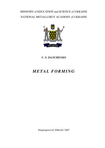
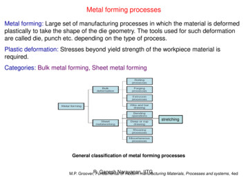
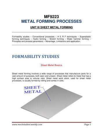
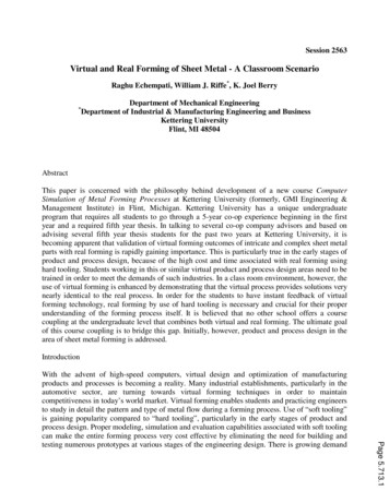
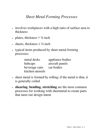
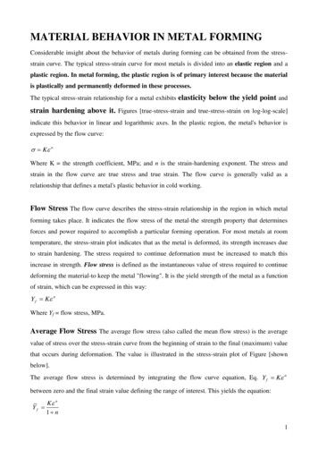
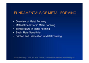
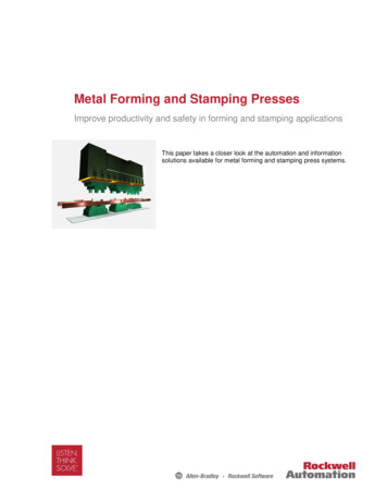
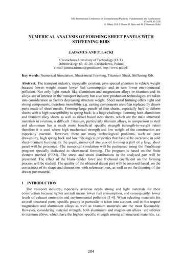
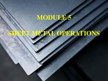
Friction 9(4): 665–685 (2021)667material leads to a high load on the tool duringforming, and as a result, the problem of gallingbecomes more pronounced [15–17].In cold stamping of a steel sheet with a gradeexceeding 590 MPa, the contact pressure reaches800 MPa locally, and the tool surface is easilyseized and damaged in the case of a normal toolsteel without any hard coating, as shown inFig. 1(a) [18]. Because of the high local pressure,the flanges and bead parts are the regions wheredamage is commonly found. In cold bending of agalvanized steel sheet with a grade of 1,180 MPa,adhesion occurs due to sliding with a velocityof175 mm/s [19], as illustrated in Fig. 1(b).Generally, bending tests are used to evaluate thedurability and adhesion of hard coatings on thetool to prevent direct contact between the tool andthe workpiece. In the cold/warm deep drawingprocess of square cups with a forming speed of3 mm/s using a 590 MPa steel, the effect of the toolcoating and lubricant on the occurrence of adhesionhas been analyzed, and the results have shownthat forming at elevated temperatures tends tolead to galling [5].Typical examples of surface damage in hotstamping of aluminum are presented in Fig. 2(a)[20]. In the hot strip drawing test of an Al–Sicoated HSS sheet, an area of severe abrasive wearis found that precedes a thick layer of compactiongalling at higher temperatures ( 600 ) whileadhesive wear is dominant at lower temperatures( 600 ), as shown in Fig. 2(b) [21].2.2Bulk metal formingIn the combined forward and backward extrusionprocess, galling easily occurs on the sizing lands ofthe punch in backward extrusion and on the die inforward extrusion under dry conditions after threeextrusion cycles [22], as shown in Fig. 3. Highfriction is generated at the interface between theworkpiece and tooling. Once even a small adhesiondamage is initiated on the tooling, more seriousgalling forms under the large surface expansion inbulk-forming. In the backward extrusion processwith a reduction in the cross-sectional area of 50%under an initial punching speed of 150–200 mm/s,galling appears at the bottom of the puncheswhere the relative sliding velocity is high and atthe inner surfaces of the cup because this portionundergoes the largest surface area expansion [23],as shown in Fig. 4. To observe the process ofgalling generation, a rotating extrusion test with aconic punch was proposed. Scratches on the punchwere observed and the frictional force wasmeasured (Fig. 5) [24]. Two stages, including compression with large bulk deformation and slidingunder a holding pressure, were carried out in thesliding compression test, in which sliding platesFig. 1 Galling appearance in high-strength-steel forming. (a) Example of galling damage in sheet forming [18]. Reproducedwith permission from Ref. [18], The Japan Society for Technology of Plasticity 2007. (b) Observation of galling duringfundamental tests. Reproduced with permission from Ref. [19], The Japan Society for Technology of Plasticity 2015.http://friction.tsinghuajournals.com www.Springer.com/journal/40544 Friction
Friction 9(4): 665–685 (2021)668Fig. 2 Galling appearance in sheet forming at elevated temperatures. (a) Surface failure of AA6061 in hot stamping.Reproduced with permission from Ref. [20], Springer Nature 2018. (b) Drawn surface appearance on coated steel sheet atelevated temperatures. Reproduced with permission from Ref. [21], Elsevier B.V. DieFig. 3GallingGalling on sizing lands. Reproduced with permission from Ref. [22], Elsevier B.V. 2017. https://mc03.manuscriptcentral.com/friction
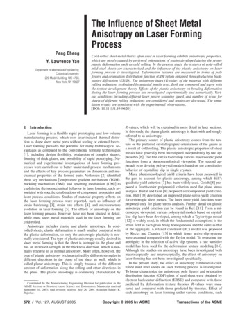
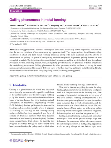
Friction 9(4): 665–685 (2021)669WorkpiecePunchGallingFig. 4Galling appearances in backward extrusion.Reproduced with permission from Ref. [23], Elsevier B.V.2012.Fig. 5 Galling and friction behavior in rotational andbackward extrusion. Reproduced with permission from Ref.[24], Elsevier B.V. 2012.blasted with S390 abrasive shots were used; immediateadhesion of the plates was observed during thefirst test [25].At elevated temperatures, the galling phenomenaare even more complex, especially in bulk-forming.The mechanisms of the degradation of hot forgingtools are complex, as abrasive wear, oxidization,thermomechanical fatigue, and plastic deformationoccur simultaneously and interact with each other[26]. Abrasive wear probably starts with adhesion.The mechanisms resulting in the transfer of aluminumon hot forming tools have been investigated fromthe standpoint of chemical and metallurgical interactions between the surfaces and mechanical interactions related to surface finish. Adhesion patchesgrew by adding more aluminum to the materialalready transferred in previous cycles [27]. In thewarm and hot upsetting sliding tests, the contactorsurface was heated to 200 by an embedded heatingcartridge, whereas specimens made of AISI 4820steel with a diameter of 30 mm were heated to1,200 in an induction furnace and cooled downin the air to 1,100 . The adhesion of the contactor(Fig. 6) could be observed with different degreesof deformation of the specimens after a test inwhich lubricant was not applied [28].2.3Evolution of galling phenomenaFigure 7 shows the basic idea of the evolution ofgalling phenomena in metal forming. Many factorscontribute to galling. In different metal formingprocesses, the controlling factors are quite different,and their relationships are very complex. Consideringthe phenomena at the point where galling occursat the tool-workpiece interface, initiation of gallingoccurs as a result of direct contact. This state canbe understood by the destruction of the followingthree layers: (1) appearance of a surface beinggenerated simultaneously with the destruction ofthe oxide film due to enlargement of the surfacearea of the workpiece, (2) breakage of the lubricantoil film due to a decrease in the kinematic viscositycaused by an increase in the interface temperature,and (3) the breakage of the thin hard coating of thetool’s surface layer. This phenomenon is derivedfrom the thermal stresses on the tool surface. Anunderstanding of the above three factors is importantin devising measures to prevent galling. Dependingon the number of machining cycles, the frictionalstate changes as a result of a micro-gallin phenomenon.This point is often considered in modeling as a slipdistance related to the number of cycles. The PVvalue is also important in the field of tribology, butthe PV value is insufficient to represent the lubricationcondition on the surface. Information on the localsurface temperature (or heat) of the tool is asimportant as information on the local surfaceunder boundary lubrication conditions.2.4Effects of temperature on gallingGalling is affected by the frictional surface temperature.http://friction.tsinghuajournals.com www.Springer.com/journal/40544 Friction
Friction 9(4): 665–685 (2021)670Controlling the temperature in systems is essentialsince friction depends on the interface temperature[29]. The interface temperature is affected by theheat due to friction, heat due to plastic deformation,and the heat of the workpiece. Theoretically, thegenerated heat at the interface can be estimatedthrough the flash temperature theory based on theassumption of the real contact area ratio and uniforminterface [30–32]. Experimentally, the interfacetemperature distribution in metal forming is difficultto measure due to its severe condition. As it is notpossible to install a temperature sensor near thecontact surface, thermocouples are placed as closeto the interface as possible. In practice, a method isadopted in which sensor holes and grooves aremachined to install the thermocouples on the backsideof the tool. The hole is made as small as possibleso as not to affect the strength of the tool and heattransfer. Following embedding of the thermocouples,the temperature evolution (Fig. 8(a)) on the punchin extrusion [33], variation in temperature on theside of a forging die as a function of forging speed(Fig. 8(b)) [34], and temperature distribution of theroll [35] were obtained. The detected temperatureAdhesionFig. 62018.Adhesion of material on the tool in warm penetration tests. Reproduced with permission from Ref. [28], Elsevier B.V.Fig. 7Galling process during metal forming. https://mc03.manuscriptcentral.com/friction
Friction 9(4): 665–685 (2021)Fig. 8671Temperature measurement with thermocouples. (a) In extrusion punch. Reproduced with permission from Ref. [33], Elsevier Science S.A. 1999. (b) In side forging die. Reproduced with permission from Ref. [34], Elsevier Science Ltd. 2002.change depends on the distance from the interfaceto the thermocouple and the heat capacity.The adhesion force is measured through a burnishingprocess under elevated temperatures [36]. Measurements show that the adhesion force is strengthenedat elevated temperatures around 700 and thatthe temperature of the contact surface is roughlyhalf the melting point of the material. The adhesionforce increases with temperature rise, sliding speed,and diffusion progression. The relation betweengalling and interface temperature is investigatedby different friction testing methods such as thestrip reduction test (Fig. 9(a)) and twist compressiontest (Fig. 9(b)) with relatively little plastic deformation.The measured temperature distribution and thevalues obtained from finite element analysis are ingood agreement [37, 38]. To obtain a precise simulationresult, it is necessary to measure the heat transfercoefficient between the tool and the workpiece.3Anti-galling methodsAs mentioned above, the destruction of the protectivefilm leads to galling. Therefore, galling can bepreventing or delaying the destruction of the film.Although it is true that galling in metal formingshould be avoided depending on the die design, inthe case where process conditions closer to thecritical state must be adopted in the design, amethod that expands this critical condition is impliedby the galling mechanism. In this section, variousapproaches for preventing galling and wear duringhttp://friction.tsinghuajournals.com www.Springer.com/journal/40544 Friction
Friction 9(4): 665–685 (2021)672Fig. 9 Temperature evolution from measured and simulated results. (a) In strip reduction test. Reproduced with permissionfrom Ref. [37], CIRP. Published by Elsevier Ltd. 2004. (b) In twist compression test. Reproduced with permission from Ref. [38], Elsevier B.V. 2007.metal forming will be introduced.3.1Improvement of lubricant performanceThe role of the lubricating film in metal forming isfrictional force reduction and tool release. It isimportant to keep sufficient amounts of lubricantat the interface from the beginning to the end ofprocessing; however, it is generally known thatkinematic viscosity rapidly decreases with increasingtemperatures and decreasing film thickness [39].As an example, the local tool temperature inforging, could reach up to 600 [40]. The firstprinciple of galling prevention is that the lubricantsmaintain the desired film thickness at elevatedtemperatures. Therefore, it is essential to raisetheir critical temperature by extreme pressureadditives [41, 42]. In hot forging, their function isslightly different from that of ordinary lubricants,and the purpose is to facilitate the tool releasing andtool cooling processes. Graphite and white lubricantsare mainly used in this process. Attention is alsobeing paid to solid lubricants suitable for hightemperature forming [43] (Fig. 10). A study [44] toimprove formability by controlling the heat transferby the choice of the lubricant (Fig. 11) is also beingconducted. From environmental-free, some examplesof lubrication with organic oils have been triedand recently reported [45]. https://mc03.manuscriptcentral.com/friction
Friction 9(4): 665–685 (2021)Fig. 10673Lubricant evaluation at elevated temperatures. Reproduced with permission from Ref. [43], Elsevier Ltd. 2014.3.2Fig. 11 Improvement of formability of AA7075 in sheetforming. Reproduced with permission from Ref. [44], Elsevier Ltd. 2017.Improvement of anti-galling by coating theworkpieceIn cold forging, chemical conversion coatings composedof soap and phosphate are generally used to maintaina protective film under contact pressures as highas 3,000 MPa [46]. The improvement in gallingresistance by phosphoric acid coatings is studiedin detail in Ref. [47]. Researchers are also lookingfor alternative methods that are more eco- friendlyfrom the viewpoint of industrial wastewater treatmentrelated to conversion coating treatment [48]. Amethod for creating a new lubricating film forforging, which is used to replace the phosphateplus soap coating, has been proposed, and its gallinghttp://friction.tsinghuajournals.com www.Springer.com/journal/40544 Friction
Friction 9(4): 665–685 (2021)674properties have been noted [49].In forming HSS sheets, Al–Si coatings have beenapplied to the workpiece, and galling propertieswere investigated in Ref. [50]. Furthermore, forgalvanized HSS sheets, products specialized forenhancing galling resistance have been released[51]. Parts formed from Al–Si coated blanks exhibitedlower mass loss but more aggressive wear behaviorthrough adhesive wear of the die, while the workpiecerelated mass loss was higher for Zn–Ni. In thelatter case, however, considerable metallic build-uplayers on the die did not occur [52].3.3Improvement of anti-galling by coated toolsAn effective means for reducing galling in metalforming is smoothing of the tool surface andbringing the contact surface closer to the fluidlubrication state. For smoothing, to minimize thelevel of irregularities, polishing is used as in thepast, but there are economic restrictions. Coatingis a surface modification method capable ofstabilizing the boundary lubrication condition duringprocessing by smoothing the surface and strengthening the vicinity of the tool surface.Two physical vapor deposition (PVD) processesto make Cr and nitride layers on the surface,namely electron beam PVD (EBPVD) and unbalancedmagnetron sputtering (UMS), have been investigated.The galling wear resistance of coatings depositedby UMS is approximately ten times that of theEBPVD coatings (Fig. 12), and the crystal orientationof the chromium coatings appears to play a significantrole [53]. In cold sheet metal stamping, a PVDtreatment of CrN on the D53 mold surface enhancesthe hardness to 1,600 HV, and the obtained goodanti-adhesive properties of the surface significantlyimprove its galling resistance [54], as shown inFig. 13. In hot aluminum forming, a hexagonalboron nitride (h-BN) coating has been used toimprove the anti-galling property of the tool.Results from load-scanner tests at an elevatedtemperature of 400 reveal that large h-BN powdersize and low h-BN concentration can help [55].Ti–Al–N coatings with Ta have proven to enhancehardness, thermal stability, and oxidation resistance;however, by optimizing the chemical compositionof x alloyed Ti1-xAlxN coatings, the oxidationresistance can be significantly improved, resultingin a much wider range of applications [56].3.4Improvement of die materialsBy changing the chemical composition of tool steel,a new cold working tool steel with excellent capabilityin terms of galling resistance was developed [57].The anti-galling properties were evaluated by usingdifferent grades of HSS sheets in the Hat-shapedbending test. The developed tool steel was superiorto the conventional SKD 61, as shown in Fig. 14.Failed large hot forging dies were refabricatedthrough a bimetal-layer weld surfacing technologyFig. 12Coating evaluation in scratch testing. Reproducedwith permission from Ref. [53], Elsevier B.V. 2018.Fig. 13 Surface morphology after sliding of DC53 mold. (a)Quenched and tempered and (b) CrN coated. Reproducedwith permission from Ref. [54], Taylor & Francis 2018. https://mc03.manuscriptcentral.com/friction
Friction 9(4): 665–685 (2021)675after producing 25 pieces, and the feasibility of thedie with a three-layer structure was verified [58].4Fig. 14 Anti-galling tool steel for sheet forming. Reproducedwith permission from Ref. [57], Elsevier B.V. 2011.with a cobalt-based superalloy and a ferrous alloy.A hot working die with a three-layer structure wasmade of 5CrNiMo, Co03, and JXHC15, as shown inFig. 15. No failure was observed on the forging dieMeasurement methodsTo understand the galling phenomena at theinterface of tools in metal forming, it is essential tohave a technique to quantitatively measure it athigh resolution. An ASTM standard test methodG98-02 exists, wherein a block specimen is generallykept stationary while a cylindrical button specimenloaded with a constant force is rotated duringtesting, and the threshold galling stress is evaluated[59]. A new parameter, the Galling50 value, thatrepresents the stress value at which galling isexpected to occur in 50% of the tested specimenshas been presented to provide a statistically relevantmeasure of galling resistance [60]. The Galling50value has been adopted by the ASTM standard testmethod G196-08 [61]. According to the standardmethod, a galling tester that could work at roomFig. 15 Three-layer structure tool in hot forging. Reproduced with permission from Ref. [58], The Society of ManufacturingEngineers. Published by Elsevier Ltd. 2018.http://friction.tsinghuajournals.com www.Springer.com/journal/40544 Friction
Friction 9(4): 665–685 (2021)676and elevated temperatures of up to 300 hasbeen developed [62].As described in Section 2.4, the interface temperature is strongly related to the galling phenomena.Owing to the harshness of the tool interface inforging, it is quite difficult to capture the interfacetemperature. Due to the size of the sensor, thetemperature distribution obtained is limited todiscrete data [63]. Therefore, methods for detectingchanges in surface properties during the formingprocess, the forming load profile of each shot, andthe change in frictional force have been developed[64, 65]. A sensoric fastener, which could gatherthe combined force and torque sensor signals inindividual spatial directions, was invented to monitorpretensioning forces and operating loads in mechanicalconnections between components [66]. The methodcan be suitably applied to the monitoring of processand tool states in forging processes [67]. However,the force measurement is not an effective index forassessing galling because variations in the load aremostly hidden in changes in material properties,formed shapes, lubricating conditions, and otherissues. To realize online monitoring of galling inmetal forming processes, a correlation of the acousticemission signal parameters to the severity of gallingwas found, and an attempt was made to use theacoustic emission measuring technique to inspectgalling on sheet surfaces [68]. A novel wear sensor,which is printed conformal to the surface of orembedded into a material to detect the depth ofabrasion, can be additively manufactured usingdirect writing methods for in-situ monitoring ofwear and abrasion of materials [69].Fig. 162011.5Galling prediction modelingTo understand the galling phenomena, simulationtools such as the finite element method can beemployed. In addition, three groups of models,wear progression models, relation models withfriction laws, and galling growth models, can beapplied along with the galling prediction methodsdescribed in the sections that follow.5.1Friction models and gallingSeizures could be described by boundary lubricationfriction concepts [70, 71]. The frictional force isreduced in order to smoothly maintain the surfaceproperties of the tool and the workpiece, and toallow for constant maintenance of the lubricatingfilm during metal forming. In forming, as a resultof plastic deformation, sliding of a newly bornsurface occurs, so the description scheme of thetransition state is a major task of friction modeling[72]. As shown in Fig. 16, the local friction distribution affects deformation [73]. A friction modelsuitable for metal forming is desired.A friction model was established as a function ofnormal pressure and interface temperature at thetool/workpiece interface and verified in a coldforward extrusion process performed at differentreduction degrees [74]. A new friction law in colddry forming, a constant friction coefficient at lowcontact pressure (Fig. 17(a)) and an associated frictionalstress at high contact pressures were proposed andconfirmed [75]. Another friction model that candistinguish between stress states at low and highcontact pressures has been proposed. In the model,Influence of frictional distribution on plastic deformation. Reproduced with permission from Ref. [73], Elsevier Ltd. https://mc03.manuscriptcentral.com/friction
Friction 9(4): 665–685 (2021)677Fig. 17 Friction model for metal forming. (a) Relating to pressure and surface condition. Reproduced with permission from Ref.[75], CIRP. Published by Elsevier Ltd. 2014. (b) Relating to slip rate and heat transfer. Reproduced with permission from Ref.[76], Elsevier B.V. 2004.the sliding velocity, equivalent stress, and yieldstress were considered, as shown in Fig. 17(b) [76].An empirically-based friction model describesfriction as a function of the sliding distance andthe most relevant friction influencing parameters[77]. In general, to create the friction model,parameters related to galling are always introduced.5.2Wear models and gallingGalling and wear, although different, are closelyrelated, and minute changes in the frictionalcondition appear as wear on the tool as a result ofrepeated processes. Therefore, it is considered thata change in the friction condition of a surface isdue to an accumulated micro seizure condition ineach process. Under process conditions that simulatewear phenomena, surface condition is alwaysobserved as a form of wear progression rather thanone of severe galling. The concept of adhesion frictionand wear [78], and a delamination theory based onfracture mechanics [79] have been theoreticallyestablished. During cycles of adhesion wear, thehttp://friction.tsinghuajournals.com www.Springer.com/journal/40544 Friction
Friction 9(4): 665–685 (2021)678detachment of agglomerates is considered a majorcause of wear; once adhered fine particles peel off,they scratch the surface layer again. In this cycle,the adhesion wear grows until it appears as galling[80]. In the case of adhesion wear, the total slidingdistance is relatively long. Experimentally, thisphenomenon
Abstract: Galling phenomena in metal forming not only affect the quality of the engineered surfaces but also the success or failure of the manufacturing operation itself. This paper reviews the different galling conditions in sheet and bulk metal forming processes along with t