Transcription
Copeland Scroll CompressorLarge ZX Condensing Unit & EMP Rack for Refrigeration ApplicationsUser Manual
Table of contentsCopeland Scroll Large ZXCondensing Unit and EMP RackEmerson is pleased to offer Copeland Scroll Large ZX condensing unit and EMP rack forrefrigeration applications.In addition to 2-9 HP condensing unit, Emerson expands Next Generation ZX platform to12-20 HP medium temperature and low temperature condensing unit and rack, configuringwith digital modulation for best in class energy efficiency and food safety.Emerson ZX series has been highly successful in global market and enjoys proven successwith its energy savings and customer-friendly electronic features.Overview4Nomenclature7Bill of material8Envelope10Technical data12Physical layout14CoreSense controller21Network wiring31Installation34Electrical connection34Refrigeration piping installation34Location and fixing37Start up and operation41Vacuuming41Charging procedure41Check before starting & during operation42Alarm codes43Troubleshooting46Temperature sensor resistance table53Wiring diagrams54Contact lists60
Caution!When you receive a unit from Emerson or an authorized representative, it is very important to check the pressureof each unit. If it is found that packing pressure has disappeared, please contact Emerson or an authorizedrepresentative. Failure to report this may cause subsequent failure reports to be unobstructed.OverviewDamage to the unit caused by the transport process should fall within the category of insurance claims and not be amanufacturing defect. It is also advisable to inspect the rest of the unit for obvious physical damage and inform us orour authorized representative in case any is discovered.ZX Platform Condensing Unit and EMP Rack were designed based onthree factors demanded by industry users:DisclaimerThanks for purchasing Copeland Scroll Large ZX Condensing Unit and EMP Rack from Emerson. Large ZXCondensing Unit and EMP Rack exhibit market-leading quality in terms of cooling capacity and operatingrange, as part of product extension for Next Generation ZX platform in larger capacity range and installationvariants. The product is designed to operate reliably and to deliver high operating efficiencies in medium andlow temperature refrigeration applications. It also provides constant monitoring of the compressor operatingconditions and displays the running or fault conditions of the condensing unit or rack.In order to ensure the safe and reliable operation of the unit and rack, the installation of Large ZX CondensingUnit and EMP Rack must comply with industry standards. The selection, installation and maintenance of LargeZX Condensing Unit and EMP Rack must be carried out by professionals. This user manual does not includeall industry guidelines for the installation of refrigeration equipment. For loss caused by inexperienced oruntrained personnel or due to wrong installation design, it will not be a reasonable reason for responsibility.If you have any questions, please contact the local sales office for unit or rack type and serial number on thenameplate for consultation. For example, the wiring diagram supplied with each unit or rack takes precedenceover the wiring diagram in this manual if any discrepancy occurs, please refer to the attached wiring diagram inthe unit or rack.ZX condensing unit introductionZX series condensing units have gained market popularity and have achieved great success in the Asian market withtheir energy-saving and friendly control experience. ZX/ZXB/ZXD/ZXL/ZXLD units in Asia are used on-site by famousend-users and cold chain retailers. ZX platform products have been widely recognized in the global market. Speciallydeveloped models have been exported to the United States, Latin America, Europe and the Middle East markets.Receiving your unitAll units are filled with dry nitrogen at a positive pressure before transportation. The unit and package are clearlylabeled. The unit shut-off valve is equipped with a maintenance interface to check the unit pressure maintenance.4Intelligent store solutions - A most innovative approach to enterprise facility management, EmersonIntelligent Store architecture integrates hardware and services, to provide retailers a single view into their entirework of facilities and understand what facilities actually cost to operate and maintain.The Intelligent Store architecture transforms data from store equipment and controls into actionable insights.Designed to deliver value in both new and existing stores, Emerson aims to help the retailers: Make better decisions on recources investment for greatest impact Gain accurate feedback and customized service to your specific needs Reduce operational costs and boost the profitability at most convenienceEnergy efficiency - Utilizing Copeland Scroll compressor technology, variable speed fan motor, large capacitycondenser coil and advanced control algorithms, energy consumption is significantly reduced. End-users can savemore than 20% on annual energy costs rather than using hermetic reciprocating units.Reliability - Combining the proven reliability of Copeland Scroll compressors with advanced electronics controllerand diagnostics, equipment reliability is greatly enchanced. Fault code alerts and fault code retrieval capabilitiesprovide information to help improve speed and accuracy of system diagnostics. Integrated electronics provideprotection against over-current, over-heating, incorrect phase rotation, compressor short cycling, high pressureresets, low pressure cut-outs. It can also send out a warning message to an operator when there is liquid floodback,which can prevent critical damage on the unit.Intelligent StoreBetter decision makingHighest efficiencyLower enery billsReliabilityLower maintenance cost5
Large ZX Condensing unit and EMP Rack featuresNomenclature6-551Electrical codeBill of materialBase model-TFD110-110 With canopy120 Without canopyETFD 380V/420V- 3ph- 50 Hz160E Ester OilReal-time monitoring of compressor operating conditionsCompressor reverse rotation protectionCompressor over current protectionCompressor internal motor protector tripDischarge gas over heat protectionOver voltage protectionUnder voltage protectionHigh pressure protectionLow pressure cut-outRefrigerant floodback warningCompressor minimum off timeInternal thermal sensor failure warningCompressor oil shortage protectionIntelligent Store Solution: Communication and retail store monitoringE Ester OilDDesign features GenerationEMP12 to 20 HP High efficient solution for refrigeration applicationLD Digital low tempD Digital medium tempEnhanced vapor injectionTFDEMP Scroll rackScroll rack family Proven reliable modulation technology for end user energy saving, accurate temperature control andbest food safety-Base model Provides electronic diagnosis, protection and communication modules for energy-saving and reliableunit control Provides digital modulation controlEmerson unique digital technologyE5XX Standard chassis6XX Chassis for remotecondenserConfigured with CoreSense ControllerBTFD 380V/420V- 3ph- 50 HzHighly efficient, ultra-quiet and highly reliable16012 to 20 HPDLD Digital low tempD Digital medium tempCopeland Scroll Compressor technologyZXCondensing unit familyLarge ZX Condensing unitElectrical codeBill of material7
Bill of materialBill of id line filter dryer/moisture indicator Liquid receiver Pressure relief valve onliquid 10120110120110120Liquid line filter dryer/moisture indicator Liquid receiver Pressure relief valve onliquid receiver Oil separator (w/ reservoir) Oil separator (w/ reservoir) Oil filter Oil filter Accumulator AccumulatorLP transducer LP transducer HP transducer HP transducer HP Pressure gauge HP Pressure gauge LP Pressure gauge LP Pressure gauge Fixed LP switch Adjustable LP switch Fixed LP switch Adjustable LP switch Fixed HP switch Fixed HP switch CoreSense controller CoreSense controller Digital modulation Digital modulation Fan speed control Fan speed control Sound jacket Sound jacket Low ambient kit Low ambient kitElectronic oil levelprotective control Electronic oil levelprotective control Service valves Service valves Discharge line check valve Discharge line check valve Suction line header Suction line header Discharge line header Discharge line header Vapor injection Vapor injectionLiquid injection Liquid injection Emergency modeLiquid level protection(Sensor to be added) Liquid level protection(Sensor to be added) Remote condenser Remote condenser CanopyEmergency modeCanopy8Model 9
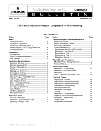
EnvelopeEMPD/EMPLD EnvelopeLarge ZX Condensing unit55Condensing temperature C48Ambient temperature CR404AZXD Digital medium temperatureR404AEMPD Digitalmedium temperatureMaximum suction gas temperature 18.3 CMaximum suction gas temperature 18.3 C20Fan speed control function for lower than 10 C ambient10-2010-20-4Evaporating temperature C-10-40Evaporating temperature C0Note: EMPD120/160BE maximum evaporating temperature is 0 C;EMPD200BE maximum evaporating temperature is -4 CNote: ZXD120/160BE maximum evaporating temperature is 0 C;ZXD200BE maximum evaporating temperature is -4 C55Ambient temperature C43Condensing temperature C48R404AZXLD Digital low temperatureMaximum suction gas temperature 5 CEvaporating temperature C-15EMPLD Digitallow temperature205-40Fan speed control function for lower than 10 C ambient10-40R404A-40Maximum suction gas temperature 18.3 CEvaporating temperature C-10-40Note: EMPLD120BE maximum evaporating temperature is 0 C;EMPLD160/200BE maximum evaporating temperature is -4 CNote: ZXLD120BE maximum evaporating temperature is 0 C;ZXLD160/200BE maximum evaporating temperature is -4 C1011
Technical dataTechnical dataLarge ZX condensing UnitNominal horsepowerZXD120BE-TFD ZXLD120BE-TFD ZXD160BE-TFD ZXLD160BE-TFD ZXD200BE-TFD ZXLD200BE-TFDHP121620Compressor3PH-380V-50 HzFan1PH-220V-50 HzProduct seriesEMPModel nameEMPD120ENominal HPHP12 C-8 /45 /18.3 / -32 /45 /18.3 /0KMax SCPowered byPerformanceR404AET/AT/RGT W2.371.402.401.322.311.43Sound pressurelevel @1mdB(A)Rated loadampereCompressorLocked totorampereAA699.6 10.16911.1 11.1747411.1 11.1Oil chargevolumeL1.9 1.8mm10214.6 14.6Soundpressure14.6 14.61021211.9 1.91.9 1.91.9 1.91.9 1.9Compressor223590590600rpm850850860Air flowm3/h192801928023400Total fan motorpowerW9509501350Oil separatoroil chargeL2.52.56Receiver volumeL171717Liquid line pipeODinchDimension(W x D x H)mm1 3/8"1 3/8"3/4"3/4"1619 x 1010 x 1124OtherPiping size1 3/8"3/4"1619 x 1010 x 1124EMPD160EEMPLD160EEMPD200EEMPLD200E1620-8/45 /18.3 /Max SC-32 /45 /18.3 /Max SC-8/45 /18.3 /Max SC-32 /45 /18.3 /Max dB(A)676666707272Rated loadampereA21.122.223.829.229.229.2Locked rotorampereA7474100102102121@1mOil type1.9 1.9Fan speedSuction pipe OD inchOther14.6 14.6kWCOPPOENumber of fanFan diameterPerformanceCapacityR404A7274Oil typeFan motorET/CT/RGT/SCEMPLD120EPOEOil chargevolumeL1.9 1.91.9 1.91.9 1.9Oil separatoroil chargeL336Receiver volume(@32 C)L404040Dimension(W x D x H)mm1619 1010 11242013 858 988Weight (net)kg244254258262290290Weight (gross)kg324334338342370370Mounting holemmSub-cooledliquid pipe OD(Evap in)inchSuction pipe ODinch(Evap out)1090 980 (4 - Φ12.0)1800 777 (6 - Φ14.0)3/43/43/41 3/81 3/81 3/8Discharge pipeOD (Cond in)inch3/43/47/8Liquid pipe OD(Cond out)inch3/43/43/42033 x 857 x 1913Weight (net)kg357kg362kg362kg362kg550kg550kgWeight (gross)kg457kg462kg462kg462kg600kg600kgNote: 12HP as preliminary data1213
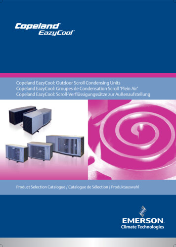
Physical layoutCircuitCircuitbreaker 1 breaker 2The following picture shows the outline of 12-16HP Large ZX condensing unit.Fan speed24VCoreSense control Transformer controllerCoreSense controllerview windowMoisture indicatorobservation windowOil observation windowFigure 1. 12-16HP Large ZX layoutThe normal oil level should be lower than the upper observation port, but higher than the lowerobservation port. If the oil level is lower than the lower observation port, replenish oil immediately.When the unit is running, replenish from the unit's suction service valve using a high pressure oil gun.Customer Contactor 1 Contactor Figure 3. Electrical module of 12-16HP Large ZXFilter drierAccumulator(LT unit only)Liquid receiverDigital compressorServicevalvesOil separator(reservoir)Fixed compressorElectronic oil controlOil filterCheck valveDischarge check valvePHE (except for ZXD120BE)EXV valve(except for ZXD120BE)Upper oil sight glassMoisture indicatorLower oil sight glassSolenoid valveService valveFigure 2. Main components of 12-16HP Large ZX14Figure 4. Service valves of 12-16HP Large ZX15
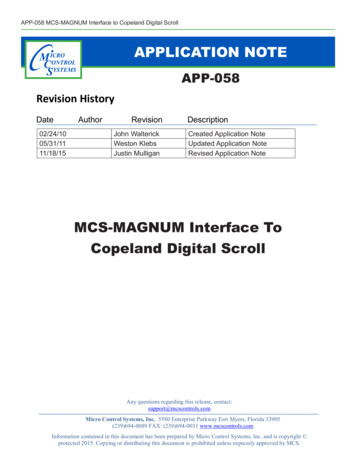
The following picture shows the outline of 12-16HP EMP Scroll Rack.Circuitbreaker 1Circuit Fan speed Alarmbreaker 2 control LED24VCoreSense Transformer controllerCoreSense controllerview windowLiquid level alarmMoisture indicatorobservation windowOil observation windowHigh/Low pressure gaugeFigure 5. EMP Rack layoutPressure safety valveCustomer Contactor 1 Contactor id receiverFigure 7. Electrical module of EMP RackDischage line check valveFix speed compressorOil separator (reservoir)Digital compressorSuction accumulator(Low temp model only)Electronic oil controlReceiver valveCompressordischargeservice valveSuction headerOil filter drierUpper oil sight glassLower oil sight glassDischarge headerMoisture indicatorElectronic expansion valvePlate heat exchanger(except EMPD120E)Suction headerCompressorsuctionservice valveHP & LP gaugeSub-cooled liquid pipe (Evap in)Core type liquid filter drierSuction pipe (Evap out)Liquid pipe (Cond Out)Discharge pipe (Cond in)Figure 6. Main components of EMP RackFigure 8. Service valves of EMP Rack1617
The following pictures shows the outlines of 20HP Large ZX condensing unit and EMP scroll rack.Fixed speed compressorDigital compressorHP guageLP guageFixed speed compressordischarge line check valveFan motorterminal boxElectronic oil controlCoreSense controllerview windowAdjustablepressure switchLiquid level alarm light(EMP Rack only)Oil filter drier Moisture indicatorLiquid filter drierPlate heat exchangerDischarge headerMoisture indicatoroberservation windowHP guageOil separatorobservation windowLP guageDischarge line check valveCheck valveOil SeparatorLiquid ReceiverAmbinet temperature sensorUpper and loweroil level sight glassLow voltage wire entry loopLiquid line service valveSuction line service valveHigh voltage wire entry loopAccumulatorSuction headerBOM-651 (Large ZX w/ remote condenser)EMPD/EMPD Scroll rack (w/o condenser)Main components for BOM-651 (w/ remote condenser) and EMP Rack (w/o condenser) :- The main components and layout are basically same with outdoor installed version condensing unit- Bigger size oil separator and liquid receiver are configured in the consideration of larger refrigerant charge in systemwith condenser remotely installed- Pay attention to the location of suction pipe, discharge pipe, liquid pipe and sub-cooled pipe and avoid wrong pipingconnectionLiquid receiverPressure safety valveDischarge line check valveOil separatorSeparate upper condenser part and lowercompressor part, add condenser inlet/outletservice valveOffer only lower compressor part, addcondenser inlet/outlet service valveCheck valveDischarge pipe (Cond in)Liquid pipe (Cond out)Suction pipe (Evap out)Sub-cooled liquid pipe (Evap in)Figure 9. 20HP layoutFigure 10. 20HP main components1819
CoreSense controllerLiquid level alarm light 2(only for EMP rack)CoreSense controllerEmergency mode switch 1(only for short time running)Compressor contactorLow voltage wire entry loopFan speed control Internal terminalsCircuit breakerTime relay(only for emergency mode)Customer terminalsHigh voltage wire entry loopLED descriptionsFigure 11. 20HP electrical moduleLED(1) Emergency mode:When electronic control system is malfunctioned, for example if controller failure occurs, emergency mode can beactivated by pressing the emergency mode switch. During emergency mode, the two compressors are running accordingto the set up on the two adjustable pressure switches:DescriptionStatusDescriptionOnCompressor 1is runningOnBrowsing theservice menuFlashingCompressor 1is ready to startFlashingBrowsing thefast access menuOnCompressor 2is runningOnA new alarm happenedFlashingCompressor 2is ready to startFlashingBrowsing thealarm menuOnCondensing fanis running1OnAn alarm is occuringOnDigital compressoris unloadingReservedOnDisplay with CFlashingProgrammable modeReserved1- When suction pressure is higher than pressure switch 1 setting, compressor 1 and fan 1&2 start up- When suction pressure is higher than pressure switch 2 setting, compressor 2 and fan 3 start up aftercertain time delay (defalt 3 min)2(2) Liquid level alarm:This function is only available on EMP Rack which requires liquid level switch to be connected onto liquid receiver as perwiring diagram instructed. When the red light turns on, it indicates low liquid level in liquid receiver, and likewise whenthe green light turns on, it indicates normal liquid level.Compressor 1(Digital) suction valveStatusCompressor 1(Digital) discharge valveCompressor 2 (Fixedspeed) suction valveCompressor 2 (Fixedspeed) discharge valveSuctionpipe valveLED!!Note:This function is available in Large ZX as standard offering. For EMP rack, this function is available only when customer has connected air cooled condenserfans to rack controller.1Compressor 1(Digital) EVIpipe valveCondenservalveLiquid pipevalveCompressor 1(Digital) oil returnhand valveCompressor 2(Fixed speed) oil returnhand valveCompressor 2(Fixed speed) EVI pipevalveOil pipehand valveLiquid receivervalveFigure 12. 20HP service valve locationNote: Figure 12 list service valve of 20HP outdoor type condensing unit. The condenser inlet and outlet pipe valve are not listed inthis picture, for details of these valve location please refer to Figure 10.2021
Bin files number rangeKeyboard descriptions - Single buttonSetStartDisplays target set point; In programming mode, select a parameteror confirm an operation.ResetHold for 5 seconds to reset any lockouts if the current state of thecontroller allow for it to be reset.UpEnter the fast access menu; In programming mode, browse theparameter codes or increases the displayed value.DownBin number XLD601-620EMPD621-640EMPLDIn programming mode it browses the parameter codeor decreases the displayed valueServiceEnter the service and alarm menu.DefrostHold for 3 seconds to start a manual defrost or terminate an activedefrost (Not available at the moment).Keyboard descriptions - Combined buttonsPress and hold for about 3 seconds to lock (Pon) or unlock (Pof) the keyboard.Pressed together to exit programming mode or menu; under rtC and PAr, thiscombination allows the user to go back to previous level.After installation and initial power on, it is critical to double check the parameters below:RTC (Real Time Clock) settingStepActionPhenomenon and description1Enter menu to select PAr (parameter) or rtC2Select rtC3Pressn01, minuten02, hourn03, dayn04, monthn05, year (last two digits)4PressDisplay actual valuePressed together for 3 seconds allows access to first level of programming mode.Pressed together for 3 seconds allows access to EXV manual setting.Controller display upon start-upStepAction1Power on controller23422Phenomenon and descriptionAll LEDs will light up for 3 seconds.56PressPressModify the valuePress SET: the value will flash for 3 seconds, then move to the nextvalueFirmware version will be displayed for 3 seconds.Parameter setting file (bin file) identifier will be displayed for 3seconds.7PressExit to rtC8PressExit to main menu (or wait for 120 seconds and exit automatically)Normal display (actual suction saturated temperature will bedisplayed)23
RefrigerantsReplacing controllerAfter a new controller is replaced and initial power is on, it is critical to reset parametersdefined on the label below the nameplate on the unit panel. Here is an example of a label:StepActionPhenomenon and description1PressEnter menu to select PAr (parameter) or rtC2PressSelect PAr (parameter)34PressPress56Browse to parameter C07PressConfirm selectionPress78Confirm selectionSelect refrigerant to be usedThe number will flash for 3 seconds and confirm the refrigerantselectionPressPressExit (or exit automatically after waiting for 120 seconds)Controller Parameter Default SettingMODELDescriptionParameterDefault ValueH07Digital Compressor MCCH09Digital Compressor Current ProtectionH27Fixed Compressor MCCH28Fixed Compressor Current ProtectionH13MIN. Operating VoltageH14MAX. Operating VoltageC07*RefrigerantNotes:*Ensure that parameter C07 is set to match the actual refrigerant used. If not,set C07 following label "Unit Operation Setting After Installation".Notes: C07 is accessible in Pr1 parameter, and the other parameters are assessible in Pr2 parameterThe step-by-step procedure to access and modify the Pr1 and Pr2 parameters are outlinedbelow:Pr1 parameter (1st level) browse and modificationEvaporating temperatureStepStep123ActionPress 3 secondsPressPressPhenomenon and descriptionPhenomenon and description1PressEnter menu to select PAr (parameter) or rtCPress SET button for more than 3 seconds, the measurement units( C) will flash together2PressSelect PAr (parameter)Modify the number for target evaporating temperature3Press SET to confirm, the number wil flash for 2 seconds (or wait forabout 10 seconds to sConfirm, select, and browse Pr1 parametersBrowse to Pr1 parametersView the actual number of the Pr1 parametersModify the actual number of the Pr1 parametersPress SET: the number will flash for 3 seconds and confirm themodifications; Will go to the next Pr1 parameterExit (or exit automatically after waiting for 120 seconds)25
Pr2 parameter (2nd level) browse and Phenomenon and description 3 secondsPressorPressPressororororPressPressorView the actual value of P1P3PressChange to next sensor code4PressChange value to“2”Browse detailed Pr2 level parameter nameSensor code andvalues descriptions(nP, noP, or nA meansthat the sensor does not exist;Err means that the sensor fails, outof range, disconnected,or does not configure properly)Exit (or exit automatically after waiting for 60 seconds)P1PSuction pressure sensorP2PCondensing pressure sensorP3tDigital compressor discharge line temperature sensorP4tPHE vapor inlet temperature sensorP5tPHE vapor outlet temperature sensorP6tAmbient temperature sensorP7tON-OFF compressor discharge line temperature sensorSHPHE superheatoPPEXV opening percentageLLSSolenoid valve status (not used)StdCondensing temperature set pointAooFan's analog output signal percentagedsoPercentage of PWM output driving the valve of the DigitalScroll compressorLtMinimum cold room temperature (unused)HtMaximum cold room temperature (unused)Change parameter setting valuestU1#1 voltage sensorConfirm the changes, changed values flash for 3 times,then display next parameter nametU2#2 voltage sensortU3#3 voltage sensortA1#1 current sensortA2#2 current sensorHmTime menuView current parameter setting valuesorEnter quick access menu, will display P1P (Press Up or Down toview other sensors)PressChange value to “3”Change value to “1”Phenomenon and description2Find parameter “t18”Confirm password & enter into Pr2 level parameterPressPress1Display “320”, “0” flashesPressPressActionDisplay “30-”, “0” flashesPressPressStep“PAS” will flash for 3 times, then display “0--”,“0” flashes (Prompt to enter pass code “321”)PressPressSelect PAr (parameter)Confirm above selection & display Pr1 level parametersPressPressEnter Menu to select PAr (parameter) or rtC, enter intoparameter browse & setting mode.Quick access menu browse - Sensor status and actual values16PressDisplay “Par”, exit parameter browse & setting mode.17PressExit to main menu27
Access alarm code (Maximum of 50 record)StepActionPhenomenon and descriptionExact timing of the alarmStepPhenomenon and description1PressDisplay SEC1PressDisplay SEC2PressDisplay A012PressDisplay A013PressDisplay alarm code in A013PressDisplay alarm code in A014PressDisplay A024PressDisplay Hr5PressDisplay alarm code in A025PressDisplay the alarm exact timing: hour.6PressDisplay MinExit (or exit automatically after waiting for 15 seconds)7PressDisplay the alarm exact timing: minute8PressDisplay dAy9PressDisplay the alarm exact timing: day10PressDisplay Mon11PressDisplay the alarm exact timing: month12PressDisplay yEA13PressDisplay the alarm exact timing: year67.Press1428ActionPressExit (or exit automatically after waiting for 15 seconds)29
Upload the parameter settings from the controller to Hot-KeyNetwork wiringDixell XWEB300D serial addressStepAction1Insert Hot-key when thecontroller is onPhenomenon and description2PressThe uPL message will appear followed by a flashing End label (Note:If Err is displayed, it means it failed to upload the program to hotkey. Please restart the process.)3PressEnd will stop flashing4Turn off the controllerand remove the Hot-key5Turn on the controller Connect to the ModBUS network using cable with 2 or 3 shielded wires, minimum section 0.5mm2(e.g. BELDEN8772). Do not connect shield to ground. Do not connect the "Gnd" terminal. Remember to draw a map of the line. This will help you to find an error if something is wrong. RS485 devices are polarity sensitive.Download the parameter settings from Hot-key to controllerStepAction1Turn off the controller2Insert Hot-key3Turn on the controllerFigure 13. Correct network wiringThe doL message will blink followed by a flashing End label (Note: IfErr is displayed, it means it failed to download the program to Hotkey. Please restart the process.)Controller will restart working with the new parameters after 10seconds45Phenomenon and descriptionRemove Hot-keyFigure 14. Incorrect network wiring3031
Dixell XWEB300D ConfigurationLarge ZX CDU / EMP Rack connected to XWEB300DXWEB300D is compatible with CDU/Rack if XWEB has the library of Large ZX and EMP Rack CoreSense controller.Large ZX CDU/EMP Rack connected to the Dixell XWEB300D with the Intelligent Store Solution module usingRS485 Modbus.Login into XWEBConnect the ZX CDU to the ModBUS network as shown on figure 15. Connect the network cable to the three-terminal connector on the XWEB300D port that has been configured asModBUS port (COM 12, 13, 14).Go to InformationInformationIf this is not present, follow the steps below: Open Dixell website ), then login(registration required)- Go to supportSystem sw update XWEB300D XWEB500 XWEB500D- Download the upgrade package with your web browser, then login into XWEB- Go to informationSystem Update MenuConnect port "13" of XWEB300D to port "485 " of CoreSense and port "12" of XWEB300D to port "485 -" ofCoreSense for RS485 communication.Provide the XW5 patch fileOnce the file has been selected wait until the upgrade procedure ends (XWEB reboots)Verify the installation ended succesfully by checking into the menu Go to Information Information for stringLog in again and setup the ZX CDU/EMP rack Go to ConfigurationDevices (drop down menu) Go to ActionsNew Enter the device name in the Name field (e.g. ZX CDU) Select "XCM25D" in the Model field Enter the ModBUS address in the RS485 Address field- Refer to setting of paramater "t01" in pr2 level in CoreSense , default setting is "1" Click NewTermination resistor for XWEB300DIf XWEB300D is placed at the beginning or end of the line, please install its termination resistor by adding ajumper in position 2 (JMP2 on the back side of the unit). Do not add the jumper if XWEB300D is placed in themiddle of the RS485 line.32Figure 15. XWEB300D connected to the Intelligent Store Solution module33
InstallationLarge ZX CDU/EMP Rack are delivered with a holding charge of neutral gas. The condensing unit should belocated in such a place to prevent any dirt, plastic bag, leaves, or papers from covering the condenser and itsfins. The unit must be installed without restricting the airflow. A clogged condenser will increase the condensingtemperature, thus reducing the cooling capacity, which leads to a high-pressure switch tripping. Clean thecondenser fins on a regular basis.Pipe runs should be kept as short as possible, using the minimum number of directional changes. Use largeradius bends and avoid trapping of oil and refrigerant. This is particularly important for the suction line. Thesuction line should ideally slope gently towards the unit. Recommendation slope is 1/200 1/250. P traps,double risers and reduced pipe diameters may be required for suction lines where long vertical risers cannot beavoided.All pipes should be adequately supported to
CoreSense controller 21 Network wiring 31 Installation 34 Electrical connection 34 . Energy efficiency - Utilizing Copeland Scroll compressor technology, variable speed fan motor, . Scroll rack family LD Digital low temp E Ester Oil TFD 380V/420V- 3ph- 50 Hz 110 With canopy 120 Without canopy