Transcription
The Influence of Sheet MetalAnisotropy on Laser FormingProcessPeng ChengY. Lawrence YaoDepartment of Mechanical Engineering,Columbia University,220 Mudd Building, MC 4703,New York, NY 100271Cold-rolled sheet metal that is often used in laser forming exhibits anisotropic properties,which are mostly caused by preferred orientations of grains developed during the severeplastic deformation such as cold rolling. In the present study, the textures of cold-rolledmild steel sheets are characterized and the influence of the plastic anisotropy on laserforming process is investigated. Deformation textures are measured in terms of polefigures and orientation distribution function (ODF) plots obtained through electron backscatter diffraction (EBSD). The anisotropy index (R-value) of the material with differentrolling reductions is obtained by uniaxial tensile tests. Both are compared and agree withthe texture development theory. Effects of the plastic anisotropy on bending deformationduring the laser forming process are investigated experimentally and numerically. Various conditions including different laser power, scanning speed, and number of scans forsheets of different rolling reductions are considered and results are discussed. The simulation results are consistent with the experimental observations.关DOI: 10.1115/1.1949620兴IntroductionLaser forming is a flexible rapid prototyping and low-volumemanufacturing process, which uses laser-induced thermal distortion to shape sheet metal parts without tooling or external forces.Laser forming provides the potential for many technological advantages as compared to the conventional forming technologies关1兴, including design flexibility, production of complex shapes,forming of thick plates, and possibility of rapid prototyping. Numerical and experimental investigations of laser forming processes were carried out to better understand process mechanismsand the effects of key process parameters on dimension and mechanical properties of the formed parts. Vollertsen 关2兴 identifiedthree key mechanisms 关temperature gradient mechanism 共TGM兲,buckling mechanism 共BM兲, and upsetting mechanism 共UM兲兴 toexplain the thermomechanical behavior in laser forming, each associated with specific combinations of component geometries andlaser process conditions. Studies of material property effects onthe laser forming process were reported, such as influence ofstrain hardening 关3兴, strain rate effects 关4兴, and microstructureevolution in laser forming 关5兴. The effects of anisotropy on thelaser forming process, however, have not been studied in detail,while most sheet metal materials used in the laser forming arecold-rolled.Anisotropy includes elastic and plastic anisotropy. In coldrolled sheets, elastic deformation is much smaller compared withthe plastic deformation, so only the anisotropic plasticity is normally considered. The type of plastic anisotropy usually desired insheet metal forming is that the sheet is isotropic in the plane andhas an increased strength in the thickness direction, which is normally referred to as normal anisotropy. More often, however, thetype of plastic anisotropy is characterized by different strengths indifferent directions in the plane of the sheet as well, which iscalled planar anisotropy. This is simply because of the differentamount of deformation along the rolling and other directions inthe plane. The plastic anisotropy is commonly characterized byContributed by the Manufacturing Engineering Division for publication in theASME JOURNAL OF MANUFACTURING SCIENCE AND ENGINEERING. Manuscript receivedSeptember 10, 2003; final revision received July 28, 2004. Associate Editor: K.Rajurkar.572 / Vol. 127, AUGUST 2005R-values, which will be explained in more detail in later sections.In this study, the planar plastic anisotropy is dealt with and simplyreferred to as anisotropy.The primary source of plastic anisotropy comes from the texture or the preferred crystallographic orientations of the grains asa result of cold rolling. The plastic anisotropic properties of sheetmetals have generally been investigated independently by two approaches 关6兴. The first one is to develop various macroscopic yieldfunctions from a phenomenological viewpoint. The second approach is to develop polycrystal models based on the constitutivebehavior of crystalline slip in single crystals.Many phenomenological yield criteria have been proposed inthe past to account for plastic anisotropy, among which Hill’squadratic yield criterion 关7兴 has been widely used. Gotoh 关8兴 proposed a fourth-order polynomial criterion used for plane stressanalysis. Barlat and Lian 关9兴 proposed a tricomponent yield criterion. Hill 关10兴 developed an improved plane-stress yield criterionfor orthotropic sheet metals. The latter three yield functions wereproposed only for plane stress analysis. Further detail on plasticanisotropy yield criterion can be found in Ref. 关11兴. From a microscopic viewpoint, various polycrystal models based on crystalline slip have been developed, among which a Taylor-type model关12兴 is widely used, in which the fundamental assumptions is thestrain field in each grain being homogeneous and the same as thatof the aggregate. A relaxed constraint 共RC兲 model was proposedby Kocks and Chandra 关13兴 in which fewer active slip systemswere assumed compared with the Taylor model. To overcome theambiguity in the selection of active slip systems, a rate sensitivemodel has been used for the deformation texture modeling 关14兴.Although the studies on anisotropy have been investigated bothmacroscopically and microscopically, the effect of anisotropy onlaser forming has not been investigated specifically.In the present study, the effect of anisotropy exhibited in coldrolled mild steel sheets on laser forming process is investigated.To better characterize the anisotropy, pole figures and orientationdistribution function 共ODF兲 plots of steel sheet were obtained byelectron backscatter diffraction 共EBSD兲 and compared with thosepredicted by deformation texture theories. R-values were measured and compared with those predicted by theories. Effect ofsuch anisotropy on laser forming under various conditions, suchCopyright 2005 by ASMETransactions of the ASME
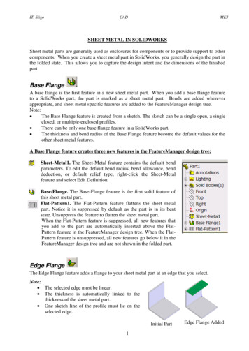
pM 0兺5r 1d 共r兲d 共2兲Taylor factor M can be compared with the reciprocal of theSchmid factor. Combinations of slip systems with the minimumTaylor’s factor will be the active slip systems in the plasticdeformation.Deformation textures calculated according to the Taylor modelare in fairly good qualitative agreement with the observed ones.However, some discrepancies exist when it was applied in largereduction cases. “Relaxed Constraint” 共RC兲 models were developed to describe texture development in large deformation. Unlikethe Taylor approach where strain compatibility is strictly prescribed, in the RC models partial constraints are imposed on thebasis of mixed boundary conditions: some components of strainand the others of stress are presumed given. For cold rolling withlarge reduction, the RC models are more accurate to predict thetexture development compared with the FC model.Fig. 1 „a Rolled-sheet coordinate system and terminology:RD, rolling direction; TD, transverse direction; and ND, normaldirection; and „b schematic laser forming system scanningpath along the RD or TDas different sheet thickness reductions, scanning speed, laserpower, as well as multiple scanning were experimentally and numerically investigated.2Background2.1 Deformation Textures in bcc Cold-Rolled SheetMetals. Sheet texture is described by the Miller index notation共hkl兲关uvw兴, in which the crystallographic plane 共hkl兲 is roughlyparallel to the sheet surface, and the direction 关uvw兴 in that planeis roughly parallel to the rolling direction 共RD兲 关Fig. 1共a兲兴. Various types of textures are possible to form in cold-rolled sheetmetal depending on material type and processing condition. Bothexperimental and simulation results have shown that four texturecomponents, 兵001其具110典, 兵112其具110典, 兵111其具112典, and 兵111其具110典,are possible in cold-rolled body centered cubic 共bcc兲 metals ofinitially random textures 关15兴. Which texture components in bccmetals are present and more dominant also depends on processcondition 关16,17兴. For instance, when rolling reduction is moderate 共i.e., 70%兲, 兵001其具110典 and 兵112其具110典 are the dominantcomponents on the -fiber, that is, 具110典 is parallel along the RD,and one sees a weak preference of 兵111其具112典 on the -fiber, thatis, 兵111其 is parallel along the normal direction 共ND兲 of the sheet.For large rolling reduction 共i.e., 70%兲 the maximum on the -fiber is shifted to 兵112其具110典 and that on the -fiber from兵111其具112典 to 兵111其具110典.To quantitatively predict the development of textures, severalmodels were developed. The most widely applied model is aTaylor-type model, which assumes that the strain of the individualcrystallite is equal to the strain of the polycrystalline aggregateand is therefore called the “Full Constraint” 共FC兲 model. In Taylor’s model, the work increment done during the tension processin terms of the macroscopic stress p and the strain increments d equals to the internal work done by the critical shear stress 共r兲0 andshear strain increments d 共r兲 in the rth slip system 共r 1 , 2 , . . . , 5兲.5 pd 兺 共r兲共r兲0 d 共1兲r 1Assuming the critical shear stress 共r兲0 is the same for all slipsystems and equal to 0. The Taylor factor can be defined asJournal of Manufacturing Science and Engineering2.2 Anisotropic Mechanical Behavior. Sheet metals withtextures exhibit anisotropic mechanical behavior, of which the twomost important measures are R-value and anisotropic yieldingstress. They are related by the anisotropy yield criterion 共Sec. 3.4兲.R-value is defined to express different contractile strain ratio andis generally applied as an index of anisotropy.R d w/d t共3兲where subscripts w and t refer to the width and thickness directions in a sheet tensile specimen extended in the length or l direction. Although R-value is commonly used to describe materialanisotropy, analysis of possible behavior is often more convenientwith a parameter , defined as: d w/d l共4兲To characterize the relations between the anisotropy and thetextures, Taylor factor M, which represents the relative strengthsof different orientations and textures, can be rewritten asM 共1/ 兲dw/d l共5兲where dw / d l is the plastic work per volume for a differentialstrain d l, and is the shear stress required for slip within thecrystals. By this definition, M can be expressed as a function of .Since M is also known as a function or crystal orientation, relations between textures and anisotropy parameters can be obtainedby M- curves. Since the material will elongate with the leastexpenditure of energy, the lowest value of M should be the appropriate one for uniaxial tension, and the corresponding value of should describe the expected shape change. Then by the assumption of constant volume 共d l d w d t 0兲, R value can be determined byR /共1 兲共6兲The above predictions are for ideal textures. The quantitativeanalysis of texture by the orientation distribution function 共ODF兲makes it possible to directly predict the relationship between texture and anisotropic properties. A general expression for the orientation dependent macroscopic property Ē共g 兲 in the orientationg isĒ共g 兲 冕E共g兲f共g兲dg共7兲where Euler space g 兵 1 , , 2其, E共g兲 is the orientation dependent property of a crystallite, and f共g兲 describing the distributionof crystalline lattice orientations. This equation has been successfully used to predict plastic, elastic, and magnetic anisotropy.AUGUST 2005, Vol. 127 / 573
3Experimental and Simulation3.1 Texture Measurement. Texture measurements of AISI1010 cold-rolled steel sheets 1.4 mm and 0.89 mm thick werecarried out using electron backscatter diffraction 共EBSD兲. A seriesof typical scans were recorded with a step size of 3 m and consisted of 3000–6000 indexed points. Four incomplete pole figures兵100其, 兵110其, 兵111其, and 兵112其 were measured in the rolling plane共RD-TD plane where TD stands for transverse direction兲. Threedimensional orientation distribution functions 共ODFs兲 f共g兲 werecalculated by using the spherical harmonics. The ODFs are represented in three-dimensional Euler space in the range of 0 deg艋 1 , , 2 艋 90 deg by way of isointensity contour lines in different sections with an Euler angle held constant. Grain structuresin different cross sections were observed by scanning electronmicroscope 共SEM兲. Samples were polished and etched using 3%HNO3 for 5 s for EBSD and 20 s for SEM.3.2 Measurement of R-Values. In accordance with theASTM Standard E517, the R-values of AISI 1010 cold-rolled steelsheets 1.4 mm and 0.89 mm thick were measured by uniaxial tensile test on a material testing machine. The specimens were cut bya CNC machine with axes along the rolling direction 共RD兲, transverse direction 共TD兲, and 45 deg to the rolling direction, corresponding to the measurement of R0, R45, and R90, where the subscripts represent the angle to the rolling direction. The specimenshave gage length of 1.6 in. 共40.64 mm兲 and width of 0.4 in.共10.16 mm兲. Due to the difficulty in measuring gage thicknesschanges with sufficient precision 关Eq. 共3兲兴, an equivalent relationship is commonly used, based on length and width strain measurements:R ln共wi/w f 兲 w 共 l w兲 ln共l f w f /liwi兲共8兲where w and l are true strains in width and length directions, wi,w f and li, l f are initial and final gage width and length, respectively. With most materials the change of R with strain l is negligible 关11兴.The R value is a very sensitive measure. Small errors in themeasured strains cause a large error in the determined R value.Measurement accuracy is improved as the strain is increased butwithin the necking limits 关18兴. According to Eq. 共8兲 the variationof the R-value can be expressed asv共R兲 冋s共 w兲2 s共 l兲2s共R兲 2 共1 R兲R w2 l册1/2共9兲where s共R兲, s共 w兲, and s共 l兲 stand for the standard deviation of R, w, and l, respectively. And the standard deviation of w can bewritten ass共 w兲 冑s共w兲2关exp共 2 w兲 1兴w20if s共w f 兲 s共w0兲 s共w兲共10兲s共 l兲 can be obtained similarly. Then the variation of R-values canbe further expressed asv共R兲 再 冉 冊1 R1 Rv共wi兲2 lR2关1 exp共 2 w兲兴 v共li兲2关1 exp共 2 l兲2兴冎1/2共11兲from which it is seen that since the variations of measurement ofinitial and final dimensions are unavoidable, a higher plastic strainwill reduce the effect of dimension measurement errors on that ofR-value. Commonly 10%–20% plastic strains are utilized in determining the R-value of low carbon steels. In the present study,approximate 15% plastic strain is utilized. The strain rate in the574 / Vol. 127, AUGUST 2005uniaxial tensile tests was taken to be 1.25 10 3 / s, which iswithin the range of the ASTM Standard 共 8.33 10 3 / s兲.3.3 Laser Forming Experiments. The material is cold-rolledAISI 1010 steel, and the workpiece size is 80 mm 80 mm withthickness of 1.4 mm and 0.89 mm. Experiments of straight-linelaser forming were carried out along the RD and TD, respectively关Fig. 1共b兲兴. The laser system used in the experiments is a PRC1500 CO2 laser, with a maximum output power of 1.5 kW andpower density distribution is Gaussian 共TEM00兲. In the presentstudy, various conditions such as different material reduction 共corresponding to two different workpiece thickness levels兲, differentscanning speed 共from 50 mm/ s to 90 mm/ s兲, different laserpower 共from 600 W to 800 W兲 and number of scans 共1 and 10兲were applied. Laser beam diameter varied from 6 mm to 4 mmwhen the sample thickness changed from 1.4 mm to 0.89 mm. Acoordinate measuring machine 共CMM兲 is used to measure thebending angle at different positions along the scanning path. Toenhance laser absorption by the workpiece, graphite coating isapplied to the surface exposed to the laser.3.4 Numerical Simulation. In numerical simulation the laserforming process is modeled as a sequentially coupled thermalmechanical process. In the thermal analysis, the transient conduction for a solid workpiece irradiated by a laser beam can be expressed in terms of temperature as c p T ⵜ · 共k ⵜ T兲 t共12兲where , c p, and k are the density, specific heat, and thermalconductivity, respectively. The heat flux due to the Gaussian laserpower is expressed asF Qmax exp共 RkR2兲 and Qmax PlaserRk/ 共13兲where Qmax is the heat flux intensity of the laser beam, R is thedistance to the laser beam center, Rk is the concentration coefficient, and Plaser is the laser power.All the surfaces of workpiece subject to the convective heat fluxthat is f h共T Ts兲, where h is the convective heat transfer coefficient, T is the surface temperature, and Ts is the surrounding temperature. The radiation heat flux is also considered at the heatingsurface which is f c 共T4 Ts4兲, where and are emissivity andStefan-Boltzmann constant, respectively.In the mechanical analysis, the deformation of a material duringlaser forming depends on the magnitude of stress, strain, andstrain rate. Due to the elevated temperature in the laser formingprocess, the strain rate has a much higher effect on the materialflow stress than at lower temperature, which in turn, influences thedeformation of the material.The total strain rate during laser forming can be decomposed cij, where ij, eij, ijp, th cij representsinto ij eij ijp thij ij , and total strain rate, elastic strain rate, plastic strain rate, thermal strainrate, and creep strain rate. Due to the short thermal cycles in laserforming, the creep can be neglected. Therefore, the term cij vanishes. The thermal strain rate can be expressed as thij Ṫ ij,where is the thermal expansion coefficient and Ṫ is the rate ofchange of temperature. By combining the elastic strain rate, plastic strain rate, and thermal strain rate components, the total strainrate can be expressed as ij 冉冊1 kk ij ij kk ij ij ij ṪE3E共14兲where is Poisson ratio, E, the Young’s modulus, the proportional factor, and the thermal expansion.For anisotropic analysis Hill’s potential function is applied instead of Von Mises function. Hill’s function is expressed in termsof rectangular Cartesian stress components asTransactions of the ASME
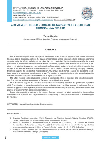
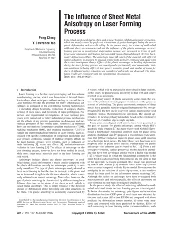
f共 兲 冑F共 22 33兲2 G共 33 11兲2 H共 11 22兲2 2L 223 2M 231 2N 212where 1, 2, and 3 represent the rolling, transverse, and normaldirections, respectively. F, G, H, L, M, and N are constants obtained by material tests in different orientations. They are definedasF 冉冊111 1 ,2 P222 P233 P211冉32P223冉,M 32P213冊1 111 ,2 P233 P211 P2221 1112 2 22 P11 P22 P33H L G ,冊N 32P212where Pij are ratios of measured yield stress to the reference yieldstress. In sheet metal forming applications plane stress conditionis generally assumed. Relative to coordinates along the principaldirections of orthotropy, the Hill’s yield criterion can be written as共G H兲 211 2H 11 22 共H F兲 222 2N 212 1共17兲The flow rule for this potential defines the incremental strain asd 11 d 关共G H兲 11 H 22兴,d 22 d 关共F H兲 22 H 11兴,共18兲d 33 d 关 G 11兴In a simple tension test performed in the rolling direction in theplane of the sheet, the incremental strain ratio can be written asd 11:d 22:d 33 共G H兲:共 H兲:共 G兲transfer analysis. A user subroutine of dflux was developed innumerical simulation. This subroutine was used to define a Gaussian distribution laser-induced flux as a function of position andwas called at each flux integration point during heat transfer procedure.4共16兲共19兲According to the definition of R-value 关Eq. 共3兲兴, it is obtained共15兲Results and Discussion4.1 Texture Characterization. Figure 2共a兲 shows the fourincomplete pole figures 兵100其, 兵110其, 兵111其, and 兵112其 of the coldrolled steel sheet with thickness of 1.4 mm. In the normal direction 共ND兲, a stronger component of 兵111其 and weaker componentsof 兵001其 and 兵112其 were seen. In the rolling direction 共RD兲, astronger 具110典 direction and weaker 具001典 and 具112典 directionswere identified. Three major components of textures 兵111其具110典,兵112其具110典, and 兵001其具110典 were therefore determined, while inthe subsequent orientation distribution function 共ODF兲 plots withmore exact components were obtained.Figure 2共b兲 shows ODF sections 共with 2 increments from0 deg to 85 deg兲 for the same material by EBSD. Most ofdeformation textures can be found with higher intensity around 2 45 deg section, as shown in Fig. 3. The -fiber texturesare 共112兲关11̄0兴 and 共001兲关11̄0兴 and the -fiber textures are共111兲关01̄1兴 and 共111兲关1̄1̄2兴. This observation is consistent withthe texture development theory 共Sec. 2.1兲.Figure 4 shows the 兵100其, 兵110其, 兵111其, and 兵112其 pole figuresobtained from steel sheet 0.89 mm thick which represents largerrolling reduction. The obvious difference can be found in 兵100其pole figure compared with that of 1.4 mm steel sheet. 兵001其 texture has disappeared and 具110典 is the major direction along therolling direction. From ODF plots, the major components of textures are determined as the -fiber 共112兲关11̄0兴 to 共111兲关11̄0兴 and共22兲 -fiber 共111兲关01̄1兴. The change of texture components is consistent to the texture development theory. That is, when rolling reduction is higher, the maximum on the -fiber is shifted to兵112其具110典 so that 兵001其具110典 components can be neglected. In the -fiber the components of textures shift from 兵111其具112典 to兵111其具110典.The grain structure at different cross sections of the cold-rolledsheet was observed by scanning electron microscope 共SEM兲. Figure 5 shows the grain structures in cross sections perpendicular tothe TD and RD directions of the cold-rolled steel sheet with thickness of 1.4 mm, respectively. It can be seen that grains are substantially elongated in the rolling direction while no significantchanges are seen along the transverse direction. This is due to thedeformation characterization of the cold rolling process. In coldrolling plates and sheets with high width-to-thickness ratios, thewidth of the material remains essentially constant and the lengthof the material is substantially elongated during rolling.In numerical simulation, the main assumptions used are as follows. Plastic deformation generated heat is small as compared toenergy input in laser forming so that it is negligible. During theentire laser forming process, no melting takes place. The symmetric plane is assumed to be adiabatic. ABAQUS was used tocomplement the numerical simulation and sequentially coupledthermal and mechanical models were applied. The same meshmodel was used for the thermal and mechanical deformations. A20-nodes brick element was used in the mechanical analysis because this kind of element has no shear locking and hourglassstiffness and is also suitable for bending-deformation-dominatedprocesses such as laser forming. In order to remain compatiblewith the structural analysis, an element, DC3D20, is used in heat4.2 Macro Anisotropic Properties, R-Value, and YieldStress. Figure 6共a兲 shows R-values determined in tensile tests fortwo different sheet reductions and along three different angles torolling direction. The pattern of R-values between the two reduction levels is somewhat similar but different in the following way.In the lower reduction case 共thickness of 1.4 mm兲, the R-valuealong the rolling direction 共RD兲, R0, is larger than that along thetransverse direction 共TD兲, R90. While in the higher reduction case共thickness of 0.89 mm兲, R0 is slightly smaller than R90. This resultis consistent with theoretical predictions.The prediction of R-values using the series expansion method isgenerally carried out within the framework of the Taylor’s model.To improve the accuracy of predictions, “Relaxed Constraint”H d 22 R0 . G d 33共20兲Similarly, for a simple tension test performed in the 90 deg and45 deg to the rolling direction,冉1HN R45 R90 and 2FG冊冉1 R0R45冊共21兲Then the yield stress ratio used in Hill’s potential function canbe expressed in terms of R-values, assuming the yield stress ratioin the rolling direction is 1,P11 1,P22 and冑R90共R0 1兲,R0共R90 1兲P12 冑P33 冑R90共R0 1兲共R0 R90兲3共R0 1兲R90共2R45 1兲共R0 R90兲Journal of Manufacturing Science and EngineeringAUGUST 2005, Vol. 127 / 575
Fig. 2 „a ˆ001‰, ˆ110‰, ˆ111‰, and ˆ112‰ pole figures of AISI 1010 cold-rolled steel sheet of1.4 mm thick; and „b orientation distribution functions „ODFs of the same samplegrain interaction models are employed 关19兴. The Taylor or fullconstraint 共FC兲 model has been shown to be more accurate inprediction at lower reduction cases. While in higher reductioncases, the relaxed constraint 共RC兲 model is more accurate due tothe more accurate boundary conditions.From Fig. 6共a兲 a very good agreement can be seen for the lowerreduction case 共thickness 1.4 mm兲, while for larger reductioncase 共thickness 0.89 mm兲, agreement is again seen for R0 and576 / Vol. 127, AUGUST 2005R90 but some discrepancy between the measured and predicatedvalues is seen for R45. A likely reason for the discrepancy is asfollows. It is known that the RC approach is appropriate for describing the deformation of aggregates of pancake-shaped grains.For cold-rolled low carbon steel, the elongated flattened grains aremostly along the rolling direction 关Fig. 5共b兲兴. As a result, thepredictions obtained from the RC model fit the experimental datasomewhat better from 0 deg to 45 deg. For angles above 45 deg,Transactions of the ASME
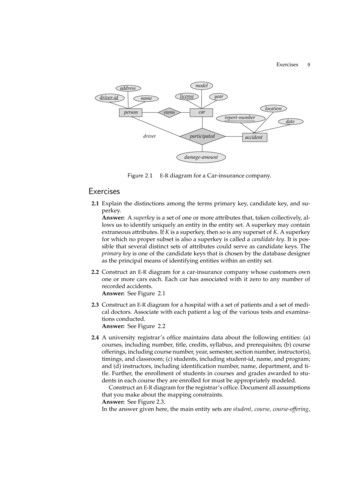
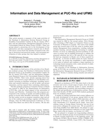
Fig. 3 Euler space „0 degÏ 1 , , 2 Ï 90 deg for a cubic crystal system and orthorhombic sample system. Two relevant textures fibers are depicted schematicallythe grains are no longer elongated along the tensile axis, so thatthe grain shape argument for using this model is not valid anymore.Figure 6共b兲 compares the yield stresses between indirectly measured values and theoretical predictions. The measured values areobtained by measured R-values and Hill’s yield criterion 关Eq.共22兲兴. As expected, the prediction based on the FC model fits thelower reduction case closely and that based on the RC model fitsthe high reduction case closely.Fig. 44.3 Anisotropic Effect on Laser Forming Involving Different Material Reductions. 80 80 1.4 mm samples werescanned along either the RD or TD. Figure 7共a兲 shows the experimental and numerical results of bending angles caused by thelaser scanning and a reasonable agreement is seen. The experiments were repeated two to three times and the repeatability isshown in terms of error bars around the data points. Bendingangles are measured at five equally spaced positions along thescanning direction. The difference between these five points is dueto the so-called edge effects which had been thoroughly studiedbefore 关20兴. But there is obvious difference in bending angle between scanning along the RD and TD. Since the flow stress in TDis smaller than that in RD 关Fig. 6共b兲兴, the bending angle whenscanned along the TD is smaller than that when scanned along RDbecause it is well known that the plastic deformation perpendicular to the scanning direction is primarily responsible for the bending angle.To further illustrate the point, Fig. 7共b兲 shows the simulatedthermal cycle and the y-plastic strain 关y is perpendicular to thescanning direction as shown in Fig. 1共b兲兴 at a location 共x 21.3 mm兲 along the scanning path. As expected, the plasticstrain is smaller when scanned along the TD than that along theRD. Scanning on the same but hypothetically isotropic material isalso superposed for comparison. The isotropic material is assumedto have R-values equal to 1 and the yield stress is 30% smallerthan that of cold-rolled sheet. The y-plastic strain of isotropicmaterial is larger due to the smaller flow stress than that of theanisotropic material.The bending angle difference of samples with thickness of0.89 mm is quite different from that of samples with thickness of1.4 mm. Since in this case the flow stress in the RD is smallerthan that of the TD 关Fig. 6共b兲兴, bending angle is smaller whenscanning along the RD than that of scanning along the TD. This isˆ001‰, ˆ110‰, ˆ111‰, and ˆ112‰ pole figures of AISI 1010 cold-rolled steel sheet of 0.89 mm thickJournal of Manufacturing Science and EngineeringAUGUST 2005, Vol. 127 / 577
Fig. 5 SEM micrographs of grain structures of cold-rolled AISI1010 steel 1.4 mm thick „Ã1000 „a cross section perpendicular to the transverse direction „TD ; and „b cross section perpendicular to the rolling direction „RD consistent experimentally and numerically as shown in Fig. 8共a兲.Figure 8共b兲 illustrates the time history of plastic strain at a location 共x 21.3 mm兲 along the scanning path and it is seen thatbending strain is smaller when scanning along the RD than that ofscanning along the TD. The thermal history of that point alsoshows that the majority of the strains occurred during the coolingcycle. Although the laser power and beam spot size applied on thetwo types of sample 共1.4 mm and 0.89 mm兲 are different, thethermal cycles on the scanning paths are almost the same due tothe same scanning speed and the combination of power and spotsize. In summary, the difference of bending deformation existswhen scanning along different directions in the anisotropic material used in this study. With the rolling reduction of steel sheetincreasing, the anisotropic effect on laser induced bending is morepronounced. Figure 9 compares bending angle difference betweenscanning along the RD and TD. In 0.89 mm thick samples thebending angle difference is almost 3 times as large as that of1.4 mm thick samples.4.4 Anisotropic Effect Under Different Scanning Speeds.Influence of plastic anisotropy on laser forming deformation undervarious scanning speeds is investigated for the 0.89 mm thickcase. Both experimental and numerical results are presented andshow agreement. From Fig. 10共a兲, it can be seen that when thescanning spe
the laser forming process were reported, such as influence of strain hardening 3 , strain rate effects 4 , and microstructure evolution in laser forming 5 . The effects of anisotropy on the laser forming process, however, have not been studied in detail, while most sheet metal materials us