Transcription
A MASTER’S GUIDE TOShips’ PipingThe StandardThis document, and more, is available online at Martin's Marine Engineering Page - www.dieselduck.net
A MASTER’S GUIDE TO SHIPS’ PIPING IS THE FOURTH PUBLICATION IN THE MASTER’S GUIDE SERIES.The Standard ClubRINAThe Standard P&I Club’s loss prevention programme focuses onbest practice to avert those claims that are avoidable and thatoften result from crew error or equipment failure. In its continuingcommitment to safety at sea and the prevention of accidents,casualties and pollution, the Club issues a variety of publications onsafety-related subjects, of which this is one. For more informationabout these publications, please contact either the Managers’London Agents or any Charles Taylor office listed in this guide.RINA activities contribute to the well-being of society as they helpto improve the quality and safety of human life and to preserve theenvironment for the future generations.Our preference is for innovative and authoritative customers whoshare our objectives of protecting quality and safety, and weestablish partnership with them to raise the standard of qualityin the relative markets.The RINA motto is “Together for excellence”The StandardAuthorsEric Murdoch BSc, MSc, C.EngDirector of Risk ManagementCharles Taylor & Co Limited1 St Katharine’s Way,London E1W 1UTUKDott.Ing Francesco SciaccaDeputy Head of Machinery Section, Marine DivisionRINA SpAVia Corsica 1216128 GenoaItalyTelephone 44 (0)20 7522 7440Email one 39 010 5385651Email Francesco.Sciacca@rina.orgwww.rina.orgThis document, and more, is available online at Martin's Marine Engineering Page - www.dieselduck.net
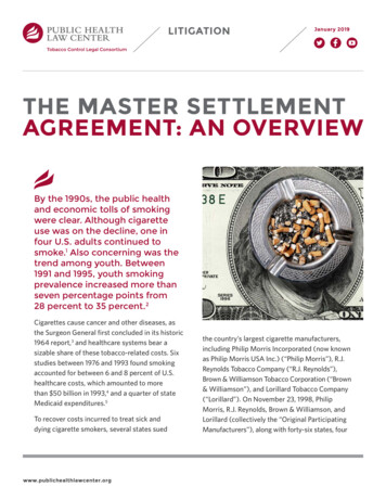
Image: Pipes with grip-type jointsCONTENTS2 Introduction3 Pipes and P&I claims4 Basic information5 Pipes and ship classification societies8 Ships’ piping systems13 Pipe design16 Causes of pipe failure20 Dealing with pipe failure21 Pipe maintenance23 Pipe repair24 Do’s and Don’ts25 Appendix I - Mechanical joints in common use27 Appendix II - Pressure test procedureThis document, and more, is available online at Martin's Marine Engineering Page - www.dieselduck.net
2INTRODUCTIONEveryone knows about the effect of corrosion on a ship’s hull, butfew people consider the effect of corrosion on piping. Pipes posea hidden danger, a danger that is often forgotten about.Pipes are silent workers, conveying fluid or allowing air to enteror to leave a space, and are the means by which many controlsystems operate. They are unnoticed until pipe failure occurs anda machine stops operating, a space floods or oil is spilled. Pipespenetrate almost every enclosed space, as well as the shell bothabove and below the waterline, and the weather deck. There is nosystem on a ship that has such enormous potential to cause fire,pollution, flooding or even total loss.The majority of ships’ pipes are constructed of ferrous material,a material that is attacked by all forms of corrosion. As a shipages, so does the piping system. Maintenance is not always easy,because pipes, unlike the hull, are difficult to examine becauseof their numbers and inaccessibility. It is practically impossibleto maintain them internally, where most corrosion takes place,and at times just as difficult to maintain a pipe’s external surface.As a result, pipes can receive minimum maintenance, and pipefailure is often the result. As an operator once remarked whenasked, “When is it necessary to replace a pipe?”, “When it bursts.”AS AN OPERATOR ONCEREMARKED WHEN ASKED,“WHEN IS IT NECESSARYTO REPLACE A PIPE”,“WHEN IT BURSTS.”The purpose of this guide is to alert ships’ crews to the danger ofcatastrophic loss that can result from pipe failure. Our intention isto raise awareness of the limit of redundancy in pipe design andthe difficulties involved in the surveying of ships’ piping. Pipefailure will only be prevented by a proactive approach toinspection, maintenance and repair.Eric MurdochThis document, and more, is available online at Martin's Marine Engineering Page - www.dieselduck.net
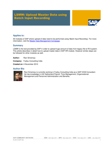
3Image: Deck cargo piping on a tankerPIPES AND P&I CLAIMSFailed pipes cause, or contribute to, many serious claims. Bagged grain on a small bulk carrier was damaged after waterescaped from an air pipe running between a ballast tank andthe cargo hold. The pipe had a corrosion crack where itconnected to the tank top and water escaped through the crackwhen the ballast tank was overfilled. The ship was 18 yearsold, but nothing had ever been done to protect the pipe fromcorrosion; not even a lick of paint. Cost – 120,000. Repairs tothe pipe would have cost less than 50. Bulk fertiliser was damaged when water escaped from atopside ballast tank via a sounding pipe that passed throughthe tank into the hold below. The pipe was cracked and holedinside the ballast tank which contained saltwater ballast andwater drained from the tank into the hold. Cost – 380,000.Damaged sounding pipes are easily identified duringinspections and repairs are inexpensive. A cargo ship foundered and four crewmen lost their lives,when a seawater-cooling pipe in the engine room burst and theengine had to be stopped. The ship was blown onto a lee shorewhere it broke up on the rocks. Cost – four lives and 1m.Corroded seawater pipes connecting directly to the shell areoften wrongly repaired with a doubler. Doublers should notnormally be used to repair shell plating. A product tanker was gravity ballasting into a segregated tank.The ballast line passed through a cargo tank. When ballaststopped flowing, a corrosion hole in the line allowed oil toescape into the sea through an open valve. Cost – 975,000. The main engine of a bulk carrier was seriously damaged whenalumina in the cargo hold got into its fuel tank. There was ahole in the air pipe that passed through the cargo hold into thetank. Cost – 850,000. The pipe had never been properlyexamined during surveys. A diesel alternator caught fire after a low-pressure fuel oil pipeburst and sprayed oil onto the exhaust manifold. The pipe hadbeen vibrating, and this movement had caused the pipe’s wallto chafe and become thin. The claim cost a new alternator and 100,000, but the fitting of a pipe support would have cost amere 2!This document, and more, is available online at Martin's Marine Engineering Page - www.dieselduck.net
4BASIC INFORMATION The majority of ships’ pipes are made of mild steel. Flow rate, viscosity and pressure of fluid being carrieddetermine a pipe’s diameter. Pipes in areas of a ship where there is a risk of gas explosionare earthed because fluid flow can build up a static electricitycharge. Bonding strips are used across flanged joints tomaintain conductivity. Pipes that pass through other compartments pose potentialsubdivision issues, especially open-ended pipes. Pipes, especially open-ended ones, compromise the integrityof the compartments they pass through. The water circulating in cooling pipes will corrode them overtime. Pipes passing through tanks containing liquid are exposed tocorrosive attack on both surfaces. Pipes carrying liquefied gas seldom suffer internal corrosion. Visual checks of the external surfaces of a pipe will not indicateits condition because it could be internally corroded and havea reduced wall thickness. Most abrasive corrosion and consequent internal thinninghappens where the pipe bends and at elbows. Liquid flowing quickly will be turbulent as a result of fluid Pipes can be joined by butt-welding, with flange connections ormechanical joints. However, the number of flange connectionsallowed in the cargo pipes of a chemical tanker is strictlycontrolled by classification society rules. Good pipe alignment during assembly of a run prevents‘locked-in’ stress. The use of expansion (mechanical) joints, such as dresser-typejoints, is restricted to locations where pipes move because ofthermal expansion or contraction, or ship bending. Classificationsociety rules prohibit their use for the connection of cargo pipingin chemical tankers. The most common expansion joints arecompression couplings or slip-on joints. A pressure test of 1.5 times design pressure is a strength test;a test at the design pressure is a tightness test. Pressure testingcan show the small cracks and holes that will not be found by avisual examination. Pipes are held in place by supports or clips that preventmovement from shock loads and vibration. Pipe failure iscommon when pipes are allowed to vibrate. Pipes carrying flammable liquids have as few joints as possibleand these are shielded to prevent leaks from coming intocontact with hot surfaces. Mechanical joints are not normally fitted on pipes carryingflammable liquids.separation and cavitation. Flow turbulence in a pipe willcause pitting. A pipe with the correct diameter for the jobwill eliminate turbulence.This document, and more, is available online at Martin's Marine Engineering Page - www.dieselduck.net
5PIPES ANDSHIP CLASSIFICATIONSOCIETIESShip classification societies publish regulations for the design andinstallation of ship piping systems, defining strength, materials,system requirements (routeing), testing procedures and surveyingrequirements.Classification society rules require ships’ pipes to be inspectedduring annual, intermediate and renewal surveys.Annual surveysPipes are checked visually. A pressure test is done if there is anydoubt as to their integrity. Pipes connecting to the shell are subjectto particular attention.Intermediate surveysThe requirements are similar to those applying to annual surveys.Renewal surveysPipes are checked visually and hammer-tested, with some alsobeing pressure-tested. The surveyor will select which pipes are tobe pressure-tested. Pipes carrying superheated steam, the firemain and those that are part of a fixed gas fire extinguishingsystem should always be tested. Some pipes might also beselected for dismantling and internal inspection.A general outline of the survey requirements for different shiptypes is shown in Table 1 on page 6.This document, and more, is available online at Martin's Marine Engineering Page - www.dieselduck.net
6CLASSIFICATIONSURVEY REQUIREMENTSClassification societies have specific requirements with regard to ships’ piping systems that follow the general survey criteriafor the rest of the ship. The table below gives an outline of these requirements.Table 1Annual SurveyALL SHIPSTANKERSBULK & DRY CARGOAll essential services are generallyexamined with particular attention givento all fixed fire extinguishing systems andto water/fire extinguishing systems. A testunder working conditions of the fire mainis arranged.In addition to the classificationrequirements applicable to the rest of theship, the surveyor will complete, as far asis possible, a general examination of allcargo, steam and water ballast piping,including pipes located on deck, in thepump room, cofferdams, pipe tunnel(s)and void spaces.In addition to the requirements for the restof the ship, piping in cargo holds and waterballast tanks are generally examined as faras is possible, including pipes on deck, invoid spaces, cofferdams and pipe tunnel(s).The bilge pumping systems are examinedand tested.Particular attention is given to: Inert gas piping to verify the absence ofcorrosion and gas leakage. A test underworking conditions is arranged. The crude oil washing system andits fittings. The pump room.This document, and more, is available online at Martin's Marine Engineering Page - www.dieselduck.net
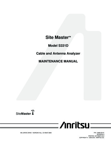
7Image: Spectacle flangeTable 1 contIntermediate SurveyALL SHIPSTANKERSBULK & DRY CARGOThe scope of intermediate surveys is thesame as annual surveys.The annual survey requirements apply;however, depending upon the surveyor’sfindings during the general examination,he may require pipes to be dismantled,hydrostatically tested and have their wallthickness measured, or all three.The scope of intermediate surveys is thesame as annual surveys.ALL SHIPSTANKERSBULK & DRY CARGOThe survey involves extensive examinationsand checks to show that all piping systemsare in satisfactory condition to allow theship to operate and for the new period ofclass to be assigned (provided propermaintenance and required interimsurveys are carried out).All piping systems within cargo tanks,saltwater ballast tanks, double-bottomtanks, pump rooms, pipe tunnel(s) andcofferdams, including void spacesadjacent to cargo tanks, and pipesthat pass through the deck or connectto the shell, are examined and testedunder working conditions. The surveyorchecks for tightness and looks to establishif their condition is satisfactory.All piping systems within cargo holds,saltwater ballast tanks, double-bottomtanks, pipe tunnels, cofferdams and voidspaces adjacent to cargo holds, and pipesthat pass through the deck or connect tothe hull, are examined and tested underworking conditions to ensure that theyremain tight.Renewal SurveyMachinery and all piping systems used foressential services are examined and testedunder working conditions, as considerednecessary by the surveyor.Steam pipes are specially examined.Superheated steam pipes with a steamtemperature exceeding 450 C requireadditional tests.In addition to the annual and intermediatesurvey requirements, fixed fire-fightingequipment is tested under workingconditions, including relevant gas bottles,which are hydrostatically tested.Compressed air pipes are removed forinternal examination and are subjectedto a hydrostatic test.In addition to annual and intermediatesurvey requirements, all machinery usedfor liquid cargo services is examined,including ventilation pipes, pressurevacuum valves and flame screens.The inert gas systems are tested underworking conditions. The systems’ maincomponents are examined internally.On the basis of results of theseexaminations, additional checks canbe required, which may includedismantling, hydrostatic tests and/orthickness measures, or all three.Piping systems for fuel or lubricatingoil are carefully examined.This document, and more, is available online at Martin's Marine Engineering Page - www.dieselduck.net
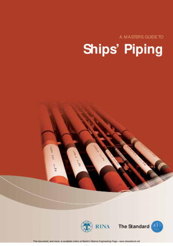
8Image: Suction filterSHIPS’ PIPINGSYSTEMSBilge systemThe bilge system is used to remove small quantities of fluid thathave leaked or condensed into a dry space. The system serves themachinery spaces, cargo holds, cofferdams, voids, stores, tunnelsand pump rooms. Each space has its own piping but the pump islikely to be shared.The capacity of a bilge system is defined by the diameter of thebilge main and pump capacity for the volume of the enclosed space.In passenger and cargo ships where the engine room providesbilge pumping, the whole ship is the ‘enclosed space’. The diameterof the bilge main is:d 25 1.68 L(B D )where,d internal diameter of bilge main, in millimetresL length between the ship’s perpendiculars, in metresB extreme breadth, in metresD moulded depth, in metresIn a tanker with a separate cargo pumping and piping system,the ‘enclosed space’ is the engine room and the diameter of thebilge main is:d 35 3 Lo (B D )where,Lo length of the engine room, in metresCargo ships are required to have two bilge pumps with non-returnvalves fitted to prevent back-flow or cross-flow.The pumping system in a passenger ship must be able to drainwater from any dry space when one or more of the ship’s othercompartments are flooded. However, the system is not required toempty the flooded space. A flooded passenger ship is required tohave at least one bilge pump, with its own power supply, availablefor pumping. Bilge suctions must have remotely operated suctionvalves. The minimum number of pumps required is three or four,depending on the ship’s design.Mud boxes and strum boxes (line filters) are fitted at the ends andin bilge lines to stop debris being sucked into the pipe.The requirements for bilge systems on ships carrying dangerousgoods are basically the same as for cargo ships. However, systemsdrawing fluids from gas-dangerous spaces are kept segregatedwith their own pumps and pipes, where appropriate, from systemsserving gas-safe spaces.This document, and more, is available online at Martin's Marine Engineering Page - www.dieselduck.net
9Image: Deck pipingSHIPS’ PIPING SYSTEMSBallast systemBallast is taken on to increase a ship’s draught, particularly thestern draught, when sailing without cargo. On a dry-cargo orpassenger ship, the ballast system is operated from the engineroom. On a tanker, the entire ballast system is located within thecargo area and is operated from a pump room. Usually small-bore piping, which is dry when not in use.A water spray system is operated manually and looks similarto a sprinkler system. Ships’ firefighting systems Sprinkler systemsSmall-bore pipes kept permanently charged with freshwater atabout 10 bar pressure. A sprinkler system is arranged to releaseautomatically at temperatures of about 70 C, so the system canboth detect and extinguish a fire. The system uses saltwaterafter the fresh. After use, it is flushed with freshwater tominimise corrosion. Some systems operate at higher pressures.CO2 pipingRelatively small bore hot galvanised mild steel piping designedto withstand the surge loads that occur with the release of CO2.Main CO2 lines are designed to withstand the same pressure asthat of CO2 bottles, while distribution lines off the main valveare designed for a lower pressure. Typically, the main line ispressure tested to 200 bar, the design pressure being at least160 bar.Fire mainMild steel piping fitted with hydrants for hoses where saltwateris used for manual firefighting. The fire main is designed for atypical working pressure of about 10 bar. Pipes in the fire mainare affected by corrosion both externally and internally. Pipesare joined with flanged connections.Inert gas (IG) pipingFitted on all tankers over 20,000 dwt and on all tankers fittedwith crude oil washing (COW) systems. IG piping is usuallylarge diameter low-pressure mild steel, with smaller diameterbranch lines. The internal surface of inert gas piping does notusually corrode. The external surface is painted but will corrodeif the paint coating deteriorates.Ballast piping is usually made of ordinary mild steel. A ship’s sizedetermines the capacity of its ballast system.Piping is used extensively throughout a ship for fire control purposes.The specific features of ships’ fire-fighting equipment are governedby the Safety of Life at Sea Convention (SOLAS). Many SOLASrequirements have been put into classification society rules.They include:Water spray systems High-expansion foamUses foam with an expansion ratio of 900 to 1 in mild steellow-pressure piping. Pressure in the lines ranges from 4 to 5bar. Foam compound in storage tanks is pumped to a foamgenerator. The system is required to deliver foam at a rate ofone metre of compartment depth per minute.This document, and more, is available online at Martin's Marine Engineering Page - www.dieselduck.net
10Image: Low expansion foam monitorSHIPS’ PIPING SYSTEMS Low expansion foamUses foam with an expansion ratio of 12 to 1 in mild steellow-pressure piping. Typical pressure in low expansion foampiping is 12 bar. Dry powderUsed mainly for the fixed fire-extinguishing system on the deckof gas carriers and on older chemical tankers. Dry powder isheld in tanks and is propelled by nitrogen gas stored inpressure bottles. Dry powder delivery pipes are pressurisedto 18 bar.Pipes carrying fuel oil andflammable liquidsThere are two principal types of pipes that carry fuel and they arecategorised by the pressure the pipe is designed to withstand.Low-pressure pipes are used to move fuel from a storage tank toa service tank to an injection pump; high-pressure pipes are usedto deliver fuel from an injection pump to an engine combustionchamber. Ships’ fuel is usually stored in double-bottom tanks,deep tanks, side bunker tanks, settling tanks or service tanks.Piping between a service tank and a fuel transfer or boosterpump is rated as low pressure. However, between each pumpingstage, pressure increases.It is a mistake to assume that even if a pipe’s pressure is relativelylow, fuel will not spray from a crack or small hole.Pipes from fuel tanks can pass through ballast tanks and pipesserving ballast tanks can pass through fuel tanks. Because ofpollution risks, classification societies have stringent rulesrestricting the length of any oil pipe passing through a ballast tank(and vice versa); it must be short, have increased wall thicknessand stronger flanges.The Safety of Life at Sea Convention (SOLAS) includesrequirements for fire safety in engine rooms. In particular, specialdouble-skinned pipes must be used to deliver fuel to enginecombustion chambers. These are made of low carbon steel alloysand operate at high pressure, between 600 and 900 bar. Doubleskins are necessary because pipe fracture will cause fuel to sprayin a fine aerosol. Fuel will ignite on contact with a hot surface,such as a turbocharger casing or exhaust pipe. The second skin isto guard against direct spraying. The pipe is designed so that fuelwill be contained in the space between the outer skin and themain pipe, and will drain into a collecting tank fitted with ahigh-level alarm.Low-pressure lubricating and fuel oil pipes passing close to a hotsurface have to be secured against the possibility of oil sprayingfrom a flange. To prevent this, the flange is usually taped. Inaddition, and whenever possible, the pipes are routed clear of hotsurfaces. Similarly, to prevent leaking oil falling onto a hot surface,pipes should never be allowed to run above a hot surface.Regular thermographic surveys of hot surfaces will identify thoserisk areas that are sufficiently hot to ignite spraying or leaking fuel.Preventive measures to be taken include additional lagging, sprayor drip shields.Fuel oil transfer pipes are usually mild steel and may corrode.The calculation for minimum wall thickness includes a smallallowance for corrosion. As a pipe ages and corrodes, leakagecan occur. Inspection programmes should concentrate onidentifying worn or corroded pipes.This document, and more, is available online at Martin's Marine Engineering Page - www.dieselduck.net
11SHIPS’ PIPING SYSTEMSEngine cooling systemWater carried in pipes is used to cool machinery. The main engineis cooled by two separate but linked systems: an open system(sea-to-sea) in which water is taken from and returned to thesea (seawater cooling), and a closed system where freshwateris circulated around an engine casing (freshwater cooling).Freshwater is used to cool machinery directly, whereas seawateris used to cool freshwater passing through a heat exchanger.The particular feature of an engine cooling system is continuousfluid flow. Fluid in motion causes abrasive corrosion and erosion.To reduce the effects of turbulent flows, seawater systemsincorporate large diameter mild steel pipes, the ends of whichopen to the sea through sea chests where gate valves are fitted.If a seawater cooling pipe bursts, both suction and dischargevalves will have to be closed to prevent engine room flooding.In order to make sure the valves operate correctly when you needthem to, open and close them at regular, say monthly, intervals.Seawater pipes are usually mild steel, but galvanised steel,copper or copper alloy are also used. Freshwater cooling pipesare generally made of mild steel.Air and sounding pipesAir pipes allow an enclosed space to ‘breathe’. They preventover-or under-pressure by letting air in or out of the space whenliquid is pumped in or out, or when temperature changes cause airor fluids to expand or contract. Cargo holds are ventilated by airpipes passing through the weather deck and these are fitted withself-closing watertight covers (headers). This is a Load Linerequirement.Sounding pipes are small-bore mild steel pipes used to measurethe quantity of fluid in a tank or a hold bilge. The pipe allows atape or sounding rod to pass through to the bottom of a tank orhold. Deck sounding pipes pass through the weather deck andare fitted with screw-down caps. Sounding pipes for engineroom double-bottom tanks are fitted with self-closing cocks.It is imperative that sounding pipe caps or cocks be kept shut.Sounding pipes are a potentially dangerous source of progressiveflooding. An engine room can be flooded through an open soundingpipe if a ship’s bottom is holed. A cargo hold can be floodedthrough an open deck sounding pipe when water is washed ondeck in heavy weather. Holes in weather deck air pipes also causehold flooding during heavy weather.Air and sounding pipes are normally constructed of mild steel.Most of the time, these pipes do not come into contact with liquid,either inside or outside. The size of an air pipe serving a tank isdetermined by comparison of the pipe’s cross-section area withthat of the pipe that will fill or empty the tank. This determination,by the designer, is to avoid the risk of over- or under-pressure.Air and sounding pipes that pass through other compartmentsare a potential source of progressive flooding. It is difficult toinspect air and sounding pipes located inside cargo spaces orballast tanks. However, the integrity of air pipes for ballast tankscan be checked by overfilling the tanks. Pipes passing through adry cargo space must be inspected for damage caused by contactwith grabs, bulldozers, etc. It is advisable to open and to inspectair pipe headers on the exposed weather deck once every fiveyears following the first special survey. This is necessary becausecorrosion on the inside of an air pipe header will not be noticeableexternally. Screw-down caps are fitted on the top of soundingThis document, and more, is available online at Martin's Marine Engineering Page - www.dieselduck.net
12Image: Ventilation pipesSHIPS’ PIPING SYSTEMSpipes. These caps should never be mislaid or replaced withwooden plugs. To extend the life of air pipe headers, they shouldbe galvanised. The self-closing cocks on engine room soundingpipes should never be tied open.Cargo piping – tankersCargo piping in tankers is usually mild steel and is protected fromrusting by external painting. Most large oil tankers have a ringmain system that allows increased operational flexibility but withthe penalty of reduced segregation. Tankers fitted with deep-wellpumps in cargo tanks have dedicated piping. Each tank will haveits own pump, pipe and cargo manifold. Stainless steel piping isinvariably used with stainless steel tanks. On chemical tankers,cargo pipes must be joined by welding. Flanged connections areallowed on oil tankers, as well as on chemical tankers at valveconnections and for fitting portable spool pieces, which areremovable short lengths of pipe used for segregation of piping.Regular pressure testing of cargo pipes is essential to detectweak points before they fail.Hydraulic piping systemsHydraulic pipes are high-pressure pipes. Hydraulics are used for: Manoeuvring the steering gear Actuating controllable pitch propellers and thrusters Control of watertight doors and valves Lifting appliances and deck equipment Opening stern, bow or side doors Moving mobile ramps for hatch covers Driving cargo and ballast pumps and for many other minorshipboard utilities.It is a requirement that hydraulic systems for steering, pitch controland watertight doors have dedicated piping and pumps.Some hydraulic fluids are highly flammable. As a result, hydraulicequipment and pipework must be kept clear of hot surfaces.Alternatively, hot surfaces must be protected by spray shields.It is important to prevent the external corrosion of hydraulic pipinglocated on deck. Hydraulic pipes operate at very high pressure andcorrosion-induced weakness frequently causes hydraulic pipes toburst. A high standard of cleanliness is necessary when workingwith, or replacing, hydraulic piping. Check the systems regularlyfor leaks, corrosion or mechanical damage.Use only good-quality and clean hydraulic fluid.This document, and more, is available online at Martin's Marine Engineering Page - www.dieselduck.net
13PIPE DESIGNClassification societies publish rules for design and fabricationof ships’ piping. The rules consider how the pipe will be used,the fluid conveyed, materials for construction, and welding andtest procedures. Ships’ piping is grouped into three categories,each of which has different technical requirements.Class I pipes have to comply with the most stringent rules. Theyinclude fuel oil pipes operating above 16 bar pressure or above150ºC, and steam pipes where the temperature exceeds 300ºC.Class II pipes fall between the two rule requirements.Class III pipes have the lowest requirements. They includefuel pipes that operate at or below 7 bar pressure and 60ºC.During design of piping systems, fluid temperature, pressureand the type of fluid conveyed have to be considered.MaterialsMost pipes are made of mild steel. But pipes that carry dangerouschemicals or particularly corrosive fluids are manufactured fromstainless steel. Some chemicals can be carried only in stainlesssteel cargo tanks and pipes. Some seawater pipes are copper, butplastic is often used for ballast, brine and sanitary pipes. The useof plastic pipes elsewhere in a system is restricted because of therequirement for them to pass a standard test for fire-resistance.It is not usual for plastic pipes to be constructed in a way that willenable them to pass the most stringent, level 1, fire test.minutes with a dry pipe at level 2 and 30 minutes with a wetpipe at level 3. Passing the level 1 fire test is the highest standard.If plastic pipes are to be used, the fire-resistance rating andclassification society rule requirements must be checked first.Pipe dimensionsA pipe is sized by its internal diameter. The required diameter ofa pipe depends on the minimum cross-section area necessaryto permit passage of a fluid of given
2 Introduction 3 Pipes and P&I claims 4 Basic information 5 Pipes and ship classification societies 8 Ships’ piping systems 13 Pipe design 16 Causes of pipe failure 20 Dealing with pipe failure 21 Pipe maintenance 23 Pipe repair 24 Do’s and Don’ts 25 Appendix I - Mechanical joints in common use 27 Appendix II - Pressure t