Transcription
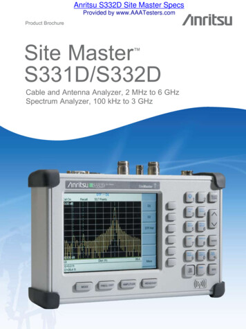
Anritsu S332D Site Master SpecsProvided by www.AAATesters.comProduct BrochureSite MasterS331D/S332D Cable and Antenna Analyzer, 2 MHz to 6 GHzSpectrum Analyzer, 100 kHz to 3 GHz
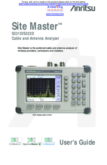
Site Master is the Preferred Cable and Antenna Analyzerof Wireless Service Providers, Contractors, and Installers. Cost Savings and Quality ImprovementWireless market competition requires operators to reduce per site maintenance expense. Site Master’s Frequency DomainReflectometry (FDR) techniques break away from the traditional fix-after-failure maintenance process by finding small,hard to identify problems before major failures occur.Sixty to eighty percent of a typical cell site’s problems are caused by problematiccables, connectors and antennas. When cables or antennas are contaminated withmoisture, damaged, or mispositioned during storms, Site Master identifies theproblem quickly. Antenna degradation reduces the cell coverage pattern and cancause dropped calls. Site Master can pinpoint the antenna problem from ground levelin a few seconds making climbing the antenna tower unnecessary.A poorly installed weather seal will corrode connectors and, if undetected, willeventually damage an expensive coaxial cable. Site Master has the sensitivity toidentify the connector problem before the cable is damaged. Distance-To-Faultprovides the clearest indication of troubled areas. ite MasterSRevolutionizesCable andAntennaSweeping inthe WirelessIndustry.Rugged and ReliableBecause the Site Master was designed specifically for field environments,it can easily withstand the day-to-day punishment of field use. The analyzer isalmost impervious to the bumps and bangs typically encountered by portablefield-equipment.Easy-to-UseSite Master operation is straightforward; measurements are obtained througha menu-driven user interface that is easy to use and requires little training.The large, and high-resolution TFT color display makes test interpretationeasy and quick. A full range of markers enable the user to make accurate measurements. Limit lines simplify measurements allowing users to create quickand simple pass/fail tests.Features local language graphical user interface support in English,Chinese, Japanese, French, German, and Spanish.2
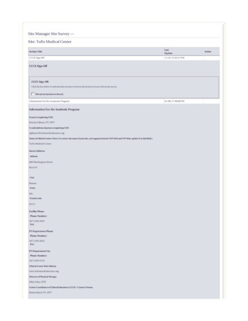
External DC Power PortRS-232 InterfaceTransfer stored data to and from a personalcomputer (PC) or download to a printer via a serialcable for further analysis. Use PC to automaticallycontrol and collect data in the field.Spectrum Analyzerand Power Meter PortCable and Antenna Analyzer PortExternal Trigger andExternal Reference InT1/E1 Receive and Transmit PortS331D Models with Option 50.Frequency Converter Module PortOption 6 (S332D) for control of an externalfrequency extension module.Snap-in Fieldreplaceable battery locationSave and Recall SetupSave setups for fast repeatabletesting:S332D Models - 25S331D Models - 10Rugged and Reliable Chassis DesignRuggedized, lightweight, compact,high-impact housing is designed towithstand repeated drops and roughhandling. Weather resistant seals andrubber membrane keypad protect unitfrom dirt and moisture.MarkersSix markers for morecomprehensive measurements.LimitsCreate simple pass/fail measurementswith a single limit line, upper and/orlower mask limit lines.TFT Color DisplayStandard TFT (640 x 480) colordisplay featuring variable brightnesscontrol. Viewable in direct sunlight.Function KeysFour dedicated function keys simplifymeasurement tasks.Multilingual User InterfaceMulti-language user interface featureson-screen menus and messages insix different languages: Chinese,English, French, German, Japanese,Spanish.Soft KeysIntuitive soft key menuand user interface.Save and Recall DisplayUp to 300 memory locations. Alphanumericdata labeling and automatic time/date stampsimplify data management.FunctionAM/FM Receiver with Internal SpeakerBuilt-in AM/FM demodulator enables testing andtrouble-shooting of wireless communications systems.An internal speaker and jack are included.BenefitsCable and Antenna Analyzer (S331D/S332D)Characterize antenna system and pinpoint location of faultsSpectrum Analyzer (S332D)Easily locate, identify and record various signals with high accuracyAM/FM Demodulator (S332D) uilt-in demodulator for AM, narrow band FM, wide band FM, and SSB allows technicianBto listen to and identify interfering signalsStandard TFT Color Display (S331D/S332D)Display is viewable in direct sunlightPower Monitor (S331D/S332D)Performs accurate broadband power measurements using an external detectorHigh Accuracy Power Meter (S331D/S332D)Performs accurate RMS power measurements for both CW and modulated signalsPower Meter (S331D/S332D)Performs accurate power measurements up to 3 GHz without the need of an external detector Frequency Converter Interface (S332D) Make measurement from 4.7 GHz to 6 GHz using an external detector MHz and 6 GHz Frequency Extensions (S331D/2S332D) xtend the lower and upper frequency ranges of the cable and antenna analyzer toE2 MHz and 6 GHz for optimum frequency coverage Built-in 12V to 24V variable Bias Tee (S332D) No need to use external power to bias an amplifierTransmission Measurement (S332D) erform a 2-port measurement and measure the insertion gain, loss, and isolation ofPTower Mounted Amplifiers, filters, attenuators, and antennasInterference Analyzer (S332D)I dentify and locate interfering signals that cause dropped calls and coverage problems.Intermittent problems can be identified using spectrogramsChannel Scanner (S332D)Measure frequency, bandwidth and power of multiple transmitted signalsCW Signal Generator (S332D)CW source to test low noise amplifiers, repeaters, and BTS receiversGPS Receiver (S331D/S332D)Provides location (latitude, longitude, altitude) and UTC time informationT1/E1 Analyzer (S331D) Simplifies the task of determining if the source of problems is on the wireline or the wireless side3
Cable and Antenna Analysis – Increase System UptimeFDR TechniqueFrequency Domain Reflectometry, (FDR), and Time Domain Reflectometry, (TDR), have similar acronyms, and bothtechniques are used to test transmission lines. But, that’s where the similarities end. TDRs are not sensitive to RF problems:the TDR stimulus is a DC pulse, not RF. Thus, TDRs are unable to detect system faults that often lead to system failures.Additionally, FDR techniques save costly, time-consuming trouble shooting efforts by testing cable feed-line and antennasystems at their proper operating frequency. Deficient connectors, lightning arrestors, cables, jumpers, or antennas arereplaced before call quality is compromised.Quick, Simple MeasurementsSite Master performs various RF measurements aimed at simplifying cable feedline and antenna analysis: Return Loss, SWR,Cable Loss and Distance-to-Fault (DTF). A single key selection on the main menu activates the desired measurement mode.Return Loss, SWRReturn Loss and SWR “system” measurements ensure conformance tosystem performance engineering specifications. Measurement easily togglesbetween either one of the two modes and can be performed without climbingthe tower.Cable LossCable Loss measurements measure the level of insertion loss within the cablefeed-line system. Insertion loss can be verified prior to deployment, when youhave access to both ends of the cable, or on installed cables without access tothe opposite end. Site Master automatically calculates and displays the averagecable loss so there is no more guess work or a need to perform calculations inthe field.Distance-to-FaultAlthough a Return Loss test can tell users the magnitude of signal reflections,it cannot tell the precise location of a fault within the feed-line system.Distance-To-Fault measurements provide the clearest indication of trouble areas as ittells us both the magnitude of signal reflection and the location of the signal anomaly.Distance-To-Fault measurement capability is built into all Site Master modelsas a standard feature. Return Loss (SWR) measurement data is processed using FastFourier Transform and the resulting data indicates Return Loss (SWR) versus distance.Distance-to-Fault measurements indicating Return Loss or SWR versus time is availablewith Handheld Software Tools . 4
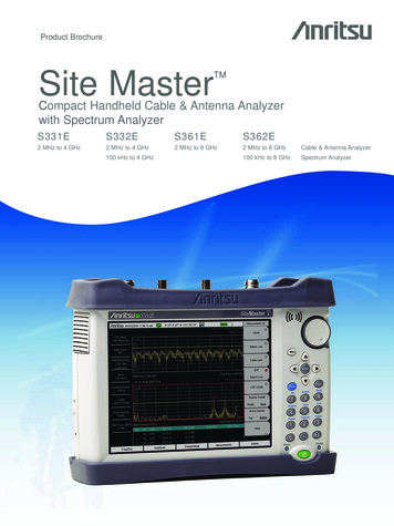
New Options Provide Cable and Antenna AnalysisCoverage from 2 MHz to 6 GHz2 MHz Frequency Extension (Option 2, S331D/S332D)The standard Site Master spans 25 MHz to 4000 MHz. Option 2 extends the lower frequency range of the cable andantenna analyzer to 2 MHz.6 GHz Frequency Extension (Option 16, S331D/S332D)Option 16 extends the standard 25 MHz to 4000 MHz frequency range of the cable and antenna analyzer to 25 MHz to6000 MHz. Option 16 used in conjunction with option 2 provides continuous coverage of the cable and antenna analyzerfrom 2 MHz to 6 GHz.OSL CalibrationOpen-Short-Load (OSL) calibration is standard for the S331D and S332D. All errors from source match, directivity andfrequency response are mathematically removed allowing for accurate vector corrected Return Loss, Cable Loss, VSWR,and DTF measurements. Directivity is usually the main contributor to measurement uncertainty, and corrected directivityof 42 dB or better is common using Anritsu’s precision components.FlexCal The Site Master FlexCal broadband calibration feature is an OSL-based calibration method. It offers field technicians asimple and convenient way to troubleshoot and identify faulty antenna system components, because it eliminates the needfor multiple instrument calibrations and calibration setups. Field technicians can now perform a broadband calibration andchange the frequency range after calibration without having to recalibrate the instrument. A zoom-in/zoom-out capability isavailable in Return Loss, Cable Loss or VSWR mode. Because the resolution and maximum distance are dependent on thefrequency range, field technicians can even change the frequency range in DTF mode to produce the desired fault resolutionand horizontal range needed for the measurement, without performing additional calibrations.InstaCal CalibrationThe InstaCal Calibration module is available in the S331D and S332Dand users can cut the time required to calibrate the Site Master by as much as50 percent. With InstaCal, users are only required to connect the InstaCalcalibration module once and the calibration process will be done automatically.Directivity specification for the InstaCal module is 38 dB for the entire frequencyrange allowing the user to make fast and accurate measurements.RF ImmunityIn today’s wireless environment it is very common that there will be other RF activity present when making a measurement.In order to make accurate measurements in hostile RF environments, the receiver has to be able to reject the unwantedsignals. Special dithering techniques are applied to the Site Master when making a measurement, and the Site Master canreject signals up to 17 dBm ensuring accurate measurements in RF rich environments.Optical Distance-To-FaultThe ODTF-1 accessory module can be used with Anritsu’s handheld cable & antennaanalyzers to make high resolution Optical DTF (Distance-To-Fault) measurements.The combination of the Site Master and ODTF-1 module provides users with an efficientsolution for characterizing both RF and Fiber Optic systems such as Remote Radio Headconfigured BTS systems.5
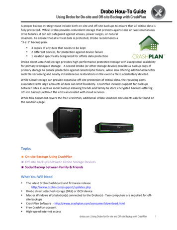
Spectrum Analysis – Anywhere, Anytime (S332D)The Site Master S332D integrated Spectrum Analysis capability provides the “ultimate” in measurement flexibility for fieldenvironments and applications requiring mobility. With the S332D you can locate, identify, record and solve communicationsystems problems quickly and easily, and with incredible accuracy – making it a perfect solution for conducting field measurements in the 100 kHz to 3 GHz frequency range.Smart MeasurementsThe S332D has dedicated routines for measurements of field strength, channel power, occupied bandwidth, Adjacent ChannelPower Ratio (ACPR), Carrier-to-Interference, and interference analysis. These are increasingly critical measurements for today’swireless communication systems. The simple interface for these complex measurements significantly reduces test time andincreases analyzer usability.Occupied BandwidthThis measurement calculates the bandwidth containing the total integratedpower occupied in a given signal bandwidth. There are two different m ethodsof calculation depending on the technique used to modulate the carrier. Theuser can specify percent of power or the “x” dB down point, where “x” can befrom 1 dB to 120 dB below the carrier.Adjacent Channel Power RatioA common transmitter measurement is that of adjacent channel leakage power.This is the ratio of the amount of leakage power in an adjacent channel tothe total transmitted power in the main channel. This measurement is used toreplace the traditional two-tone intermodulation distortion (IMD) test for systemnon-linear behavior.The result of an ACPR measurement can be expressed either as a power ratioor a power density. In order to calculate the upper and lower adjacent channelvalues, the S332D allow the adjustment of four parameters to meet specificmeasurement needs: main channel center frequency, measurement channelbandwidth, adjacent channel bandwidth and channel spacing.AM/FM/SSB DemodulatorA built-in demodulator for AM, narrowband FM, wideband FM and single sideband(selectable USB and LSB) allow a technician to easily identify interfering signals.Frequency Converter Control Module6 GHz Frequency ExtensionThe FCN4760 is a block down converter for the 4.7 to 6.0 GHz frequency range.It is designed to work with an Anritsu Site Master S332D equipped with Option 6.This converter is primarily intended for field use by fixed wireless engineers who areresponsible for the design, deployment and optimization of 802.11a networks. It is also used toconduct interference analysis measurements to determine the level of interference and locate thesources of interference.Frequency Converter Control Module
Site Master S331D/S332D Cable and Antenna Analyzer, 2 MHz to 6 GHz Spectrum Analyzer, 100 kHz to 3 GHz Anritsu S332D Site Master Specs Provided by www.AAATesters.com. 2 Site Master is the Preferred Cable and Antenna Analyzer of Wireless Service Providers, Contractors, and Installers. Cost Savings and Quality Improvement Wireless market competition requires operators to reduce per site .