Transcription
UNIT 6 KEYS AND COUPLINGSKeys and s of Keys6.2.1Sunk Keys6.2.2Saddle Keys6.2.3Tangent Keys6.2.4Round Keys6.2.5Splines6.3Forces Acting on a Sunk Key6.4Strength of a Sunk Key6.5Effect of Keyways6.6Couplings6.7Summary6.8Key Words6.9Answers to SAQs6.1 INTRODUCTIONA key is a piece of steel inserted between the shaft and hub or boss of the pulley toconnect these together in order to prevent relative motion between them. It is alwaysinserted parallel to the axis of the shaft. Keys are used as temporary fastenings and aresubjected to considerable crushing and shearing stresses. A keyway is a slot or recess ina shaft and hub of the pulley to accommodate a key.ObjectivesAfter studying this unit, you should be able to identify keys and their application, calculate forces on keys, and design keys.6.2 TYPES OF KEYSThe following types of keys are important from the subject point of view :(a)Shunk keys,(b)Saddle keys,(c)Tangent keys,(d)Round keys, and(e)Splines.We shall now discuss the above types of keys, in detail, in the following sections.6.2.1 Sunk KeysThe sunk keys are provided half in the keyway of the shaft and half in the keyway of thehub or boss of the pulley or gear. The sunk keys are of the following types :145
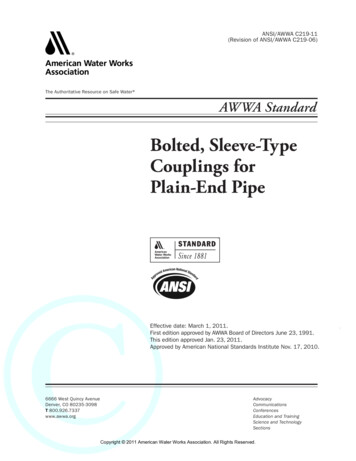
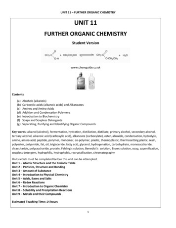
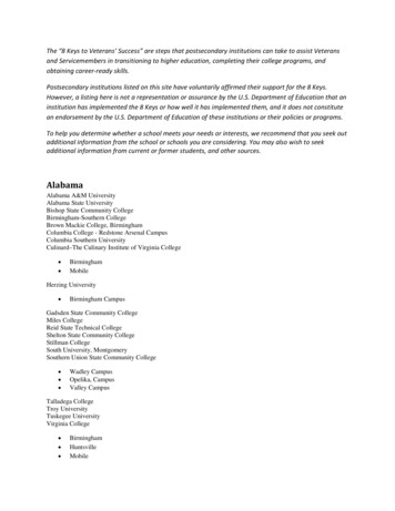
Machine DesignRectangular Sunk KeyA rectangular sunk key is shown in Figure 6.1. The usual proportions of this keyare :Width of key, w whered2w d; and thickness of key, t 364d Diameter of the shaft or diameter of the hole in the hub.The key has taper 1 in 100 on the top side only.Taper 1: 100wtdFigure 6.1 : Rectangular Sunk KeySquare Sunk KeyThe only difference between a rectangular sunk key and a square sunk key is thatits width and thickness are equal, i.e.w t d4Parallel Sunk KeyThe parallel sunk keys may be of rectangular or square section uniform in widthand thickness throughout. It may be noted that a parallel key is a taperless and isused where the pulley, gear or other mating part is required to slide along theshaft.Gib-head KeyIt is a rectangular sunk key with a head at one end known as gib head. It isusually provided to facilitate the removal of key. A gib head key is shown inFigure 6.2(a) and its use in shown in Figure 6.2(b).Taper 1:100Gib head key1.75 ttShaft1.5 tw(a)(b)Figure 6.2 : Gib-head KeyThe usual proportions of the gib head key are :Width,w d;4and thickness at large end, t 2w d .36Feather KeyA key attached to one member of a pair and which permits relative axialmovement of the other is known as feather key. It is a special key of parallel type146
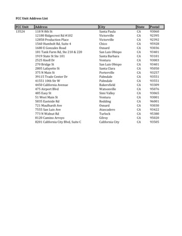
which transmits a turning moment and also permits axial movement. It is fastenedeither to the shaft or hub, the key being a sliding fit in the key way of the movingpiece.Keys and CouplingsThe feather key may be screwed to the shaft as shown in Figure 6.3(a) or it mayhave double gib heads as shown in Figure 6.3(b). The various proportions of afeather key are same as those of rectangular sunk key and gib head key.Feather keysSet screw(a)(b)Figure 6.3 : Feather KeyThe following Table 6.1 shows the proportions of standard parallel, tapered andgib head keys, according to IS : 2292 and 2293-1974 (Reaffirmed 1992).Table 6.1 : Proportions of Standard Parallel, Tapered and Gib Head KeyShaft Diameter(mm) upto andIncludingKey Cross-sectionWidth(mm)Thickness(mm)6228310Shaft Diameter(mm) upto andIncludingKey 40652012380904575221444010050Woodruff KeyThe woodruff key is an easily adjustable key. It is a piece from a cylindrical dischaving segmental cross-section in front view as shown in Figure 6.4. A woodruffkey is capable of tilting in a recess milled out in the shaft by a cutter having thesame curvature as the disc from which the key is made. This key is largely used inmachine tool and automobile construction.147
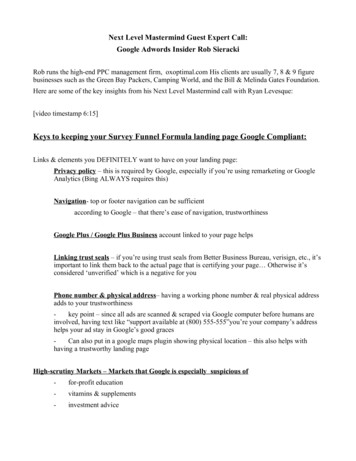
Machine DesignRFigure 6.4 : Woodruff KeyThe main advantages of a woodruff key are as follows :(a)It accommodates itself to any taper in the hub or boss of the matingpiece.(b)It is useful on tapering shaft ends. Its extra depth in the shaft preventsany tendency to turn over in its keyway.The disadvantages are :(a)The depth of the keyway weakens the shaft.(b)It can not be used as a feather.6.2.2 Saddle KeysThe saddle keys are of the following two types :(a)Flat saddle key, and(b)Hollow saddle key.A flat saddle key is a taper key which fits in a keyway in the hub and is flat on the shaftas shown in Figure 6.5. It is likely to slip round the shaft under load. Therefore, it is usedfor comparatively light loads.Hollow saddle keywtwdtFigure 6.5 : Saddle KeyA hollow saddle key is a taper key which fits in a keyway in the hub and the bottom ofthe key is shaped to fit the curved surface of the shaft. Since hollow saddle keys hold onby friction, therefore, these are suitable for light loads. It is usually used as a temporaryfastening in fixing and setting eccentrics, cams, etc.6.2.3 Tangent KeysThe tangent keys are fitted in pair at right angles as shown in Figure 6.6. Each key is towithstand torsion in one direction only. These are used in large heavy duty shafts.Figure 6.6 : Tangent Keys148
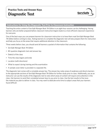
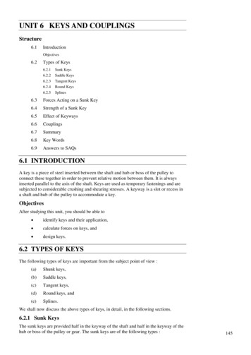
Keys and Couplings6.2.4 Round KeysThe round keys, as shown in Figure 6.7(a), are circular in section and fit into holesdrilled partly in the shaft and partly in the hub. They have the advantage ofmanufacturing as their keyways may be drilled and reamed after the mating parts havebeen assembled. Round keys are usually considered to be most appropriate for lowpower drives.Round key(a)Tapered pin(b)Figure 6.7 : Round KeysSometimes the tapered pin, as shown in Figure 6.7(b), is held in place by the frictionbetween the pin and the reamed tapered holes.6.2.5 SplinesSometimes, keys are made integral with the shaft which fit in the keyways broached inthe hub. Such shafts are known as splined shafts as shown in Figure 6.8. These shaftsusually have four, six, ten or sixteen splines. The splined shafts are relatively strongerthan shafts having a single keyway.The splined shafts are used when the force to be transmitted is large in proportion to thesize of the shaft as in automobile transmission and sliding gear transmissions. By usingsplined shafts, we obtain axial movement as well as positive drive.bdDFigure 6.8 : Splines6.3 FORCE ACTING ON A SUNK KEYWhen a key is used in transmitting torque from a shaft to a rotor or hub, the followingtwo types of forces act on the key :(a)Forces (F1) due to fit of the key in its keyway, as in a tight fitting straightkey or in a tapered key driven in place. These forces produce compressivestresses in the key which are difficult to determine in magnitude.(b)Forces (F) due to the torque transmitted by the shaft. These forces produceshearing and compressive (or crushing) stresses in the key.149
Machine DesignThe distribution of the forces along the length of the key is not uniform because theforces are concentrated near the torque-input end. The non-uniformity of distribution iscaused by the twisting of the shaft within the hub.The forces acting on a key for a clockwise torque being transmitted from a shaft to a hubare shown in Figure 6.9.ShaftF1tFFF1dFigure 6.9 : Forces Acting on a Shunk KeyIn designing a key, forces due to fit of the key are neglected and it is assumed that thedistribution of forces along the length of key is uniform.6.4 STRENGTH OF A SUNK KEYA key connecting the shaft and hub is shown in Figure 6.9.LetT Torque transmitted by the shaft,F Tangential force acting at the circumference of the shaft,d Diameter of shaft,l Length of key,w Width of key,t Thickness of key, and and c Shear and crushing stresses for the material of key.A little consideration will show that due to the power transmitted by the shaft, the keymay fail due to shearing or crushing.Considering shearing of the key, the tangential shearing force acting at the circumferenceof the shaft,F Area resisting shearing Shearing stress l w Torque transmitted by the shaft,T F dd l w 22. . . (6.1)Considering crushing of the key, the tangential crushing force acting at thecircumference of the shaft,F Area resisting crushing Crushing stress l t c2 Torque transmitted by the shaft,T F dtd l c 222. . . (6.2)The key is equally strong in shearing and crushing, ifl w 150dtd l c 222[Equating Eqs. (6.1) and (6.2)]
w c t2 orKeys and Couplings. . . (6.3)The permissible crushing stress for the usual key material is atleast twice the permissibleshearing stress. Therefore, from Eq. (6.3), we have w t. In other words, a square key isequally strong in shearing and crushing.In order to find the length of the key to transmit full power of the shaft, the shearingstrength of the key is equal to the torsional shear strength of the shaft.The torque transmitted by the key,T l w d2. . . (6.4)and the torque transmitted by the shaft,T 1 d 316. . . (6.5)(Taking 1 Shear stress for the shaft material)From Eqs. (6.4) and (6.5), we havel w l d 1 d 32 16 1 d 2 d 1 1.571d 18 w 2 (Taking w d)4. . . (6.6)When the key material is same as that of the shaft, then 1. l 1.571 d[From Eq. (6.6)]Example 6.1Design the rectangular key for a shaft of 50 mm diameter. The shearing andcrushing stresses for the key material are 42 MP and 70 MPa.SolutionGiven d 50 mm; 42 MPa 42 N/mm2; 70 MPa 70 N/mm2.The rectangular key is designed for a shaft of 50 mm diameter,Width of key, w d,4w 12.5 mmand thickness of key asd6t 8.3 mmThe length of key is obtained by considering the key in shearing and crushing.Letl Length of key.Considering shearing of the key. We know that shearing strength (or torquetransmitted) of the key,T l w d50 l 17 42 13125 l N-mm22. . . (6.7)and torsional shearing strength (or torque transmitted) of the shaft,T d3 42 (50)3 1.03 106 N-mm1616. . . (6.8)From Eqs. (6.7) and (6.8), we havel 1.03 106 79.25 mm13125151
Machine DesignNow considering crushing of the key. We know that shearing strength (or torquetransmitted) of the key,T l td8.350 c l 70 7262.5 l N-mm2222. . . (6.9)From Eqs. (6.8) and (6.9), we have106 141.8 mm8750l 1.03 Taking larger of the two values, we have length of key,l 141.8 say 142 mm.Example 6.2A 45 mm diameter shaft is made of steel with a yield strength of 400 MPa. Aparallel key of size 14 mm width and 9 mm thickness made of steel with a yieldstrength of 340 MPa is to be used. Find the required length of key, if the shaft isloaded to transmit the maximum permissible torque. Use maximum shear stresstheory and assume a factor of safety of 2.SolutionGiven d 45 mm; for shaft 400 MPa 400 N/mm2; w 14 mm; t 9 mm; yt for key 340 MPa 340 N/mm2.Letl Length of key.According to maximum shear stress theory, the maximum shear stress in the shaft, max 2 F . S. 400 100 N/mm22 2and maximum shear stress for the key, k 2 F . S. 340 85 N/mm22 2(Note : Yield strength for shaft and key materials are different).We know the maximum torque transmitted by the shaft and key,T max d 3 100 (45)3 1.8 106 N-mm1616First of all, let us consider the failure of key due to shearing. We know that themaximum torque transmitted (T),1.8 106 l w k l d45 l 14 85 26775 l221.8 106 67.2 mm26775Now considering the failure of key due to crushing. We know that the maximumtorque transmitted by the shaft and key (T),1.8 106 l l td9 340 45 ck l 17213 l Taking ck F . S. 22222 1.8 106 104.6 mm17213Taking the larger of the two value, we have152l 104.6 say 105 mm.
Keys and Couplings6.5 EFFECT OF KEYWAYSA little consideration will show that the keyway cut in the shaft reduces the load carryingcapacity of the shaft. This is due to the stress concentration near the corners of thekeyway and reduction in the cross-sectional area of the shaft. In other words, thetorsional strength of the shaft is reduced. The following relation for the weakening effectof the keyway is based on the experimental results by H. F. Moore. w h e 1 0.2 1.1 d d where ke Shaft strength reduction factor. It is the ratio of the strength of the shaft withkeyway to the strength of the same shaft without keyway.w Width of keyway,d Diameter of shaft, andh Depth of keyway Thickness of key (t ).2It is usually assumed that the strength of the keyed shaft is 75% of the solid shaft, whichis somewhat higher than the value obtained by the above relation.In case the keyway is too long and the key is of sliding type, then the angle of twist isincreased in the ratio k as given by the following relation : w h k 1 0.4 0.7 d d where k Reduction factor for angular twist.Example 5.3A 15 kW, 960 rpm motor has a mild steel shaft of 40 mm diameter and theextension being 75 mm. The permissible shear and crushing stresses for the mildsteel key are 56 MPa and 112 MPa respectively. Design the keyway in the motorshaft extension. Check the shear strength of the key against the normal strength ofthe shaft.SolutionGiven P 15 kW 15 103 W; N 960 rpm; d 40 mm; l 75 mm; 56 MPa 56 N/mm2; c 112 MPa 112 N/mm2.We know that the torque transmitted by the motor,T P 60 15 103 60 149 N-m 149 103 N-mm2 N2 960Let w Width of keyway or key.Considering the key in shearing. We know that the torque transmitted (T).Assuming that length of the key is equal to length of the shaft (i.e. extension)149 103 l w w 149 10384 103d40 75 w 56 84 103 w22 1.8 mmThis width of keyway is too small. The width of keyway should be at least w d 40 10 mm44d.4153
Machine DesignSince c 2 , therefore, a square key of w 10 mm and t 10 mm is adopted.According to H. F. Moore, the shaft strength factor,t w h w t ke 1
A key is a piece of steel inserted between the shaft and hub or boss of the pulley to connect these together in order to prevent relative motion between them. It is always inserted parallel to the axis of the shaft. Keys are used as temporary fastenings and are subjected to considerable crushing and shearing stresses. A keyway is a slot or recess in a shaft and hub of the pulley to accommodate .