Transcription
Site MasterTMModel S331DCable and Antenna AnalyzerMAINTENANCE MANUAL490 JARVIS DRIVE · MORGAN HILL, CA 95037-2809P/N: 10580-00101REVISION HPRINTED: OCTOBER 2012COPYRIGHT ã 2004-2012 ANRITSU CO.
Table of Contents1. Introduction . . . . . . . . . . . . . . . . . . . . . . . . . . . . . . . . . . . . . . . . . . . 12. Description . . . . . . . . . . . . . . . . . . . . . . . . . . . . . . . . . . . . . . . . . . . . 13. VNA Frequency Accuracy . . . . . . . . . . . . . . . . . . . . . . . . . . . . . . . . . . . . 14. VNA Return Loss Verification . . . . . . . . . . . . . . . . . . . . . . . . . . . . . . . . . . 25. Power Monitor Verification (Option 5) . . . . . . . . . . . . . . . . . . . . . . . . . . . . . 36. Power Meter Verification (Option 29) . . . . . . . . . . . . . . . . . . . . . . . . . . . . . . 57. T1/E1 Verification (Option 50). . . . . . . . . . . . . . . . . . . . . . . . . . . . . . . . . . 88. InstaCal Module Verification . . . . . . . . . . . . . . . . . . . . . . . . . . . . . . . . . 129. Battery Pack Removal and Replacement . . . . . . . . . . . . . . . . . . . . . . . . . . . 1310. Battery Information . . . . . . . . . . . . . . . . . . . . . . . . . . . . . . . . . . . . . . 1511. Front Panel Assembly Removal and Replacement. . . . . . . . . . . . . . . . . . . . . . 1712. LCD Assembly Replacement . . . . . . . . . . . . . . . . . . . . . . . . . . . . . . . . . 1913. Key Pad PCB Replacement . . . . . . . . . . . . . . . . . . . . . . . . . . . . . . . . . . 2014. Key Pad Membrane Replacement . . . . . . . . . . . . . . . . . . . . . . . . . . . . . . 2115. Main PCB Assembly Replacement . . . . . . . . . . . . . . . . . . . . . . . . . . . . . . 2216. Option 5 Power Monitor PCB Assembly Replacement . . . . . . . . . . . . . . . . . . . 2317. Option 50 T1/E1 Tester PCB Assembly Replacement . . . . . . . . . . . . . . . . . . . . 2418. Accessories and Replaceable Parts . . . . . . . . . . . . . . . . . . . . . . . . . . . . . . 2519. Customer Service . . . . . . . . . . . . . . . . . . . . . . . . . . . . . . . . . . . . . . . 27Site Master MMi
1. IntroductionThis manual provides maintenance instructions for the Site Master Model S331D Cable, Antenna andBase Station Analyzer. It describes the product and provides performance verification procedures, partsreplacement procedures, and a replaceable parts list.2. DescriptionThe Site Master is a handheld SWR/RL (standing wave ratio/return loss), Distance-To-Fault and powermeter (optional) measurement instrument. It combines a synthesized source, a VSWR Bridge, and receiver circuitry in a compact instrument.The following sections contain tests that can be used to verify the performance of the Site Master ModelS331D.Throughout this manual, the term “VNA” may be used to denote Return Loss, SWR, Cable Loss and DTFmodes. All other modes are referenced individually.3. VNA Frequency AccuracyThe following test can be used to verify the CW frequency accuracy of the Site Master. Measurement calibration of the Site Master is not required for this test.a. Equipment Required:· Spectrum Analyzer Anritsu Model MS2665C or equivalent· 10 MHz Reference Standardb. Procedure:1. Connect a 10 MHz Reference signal to the 10 MHz STD Ref In of the MS2665C or equivalent.2. Press and hold the ESCAPE/CLEAR key, then press the ON/OFF key to turn on the Site Master.(This sets the instrument to the factory preset state.)NOTE: Before continuing, allow a five minute warm up for the internal circuitry to stabilize.3. Press the FREQ/DIST key, then press the F1 soft key and set F1 to 1000 MHz, then press theENTER key.4. Press the F2 soft key, set F2 to 1000 MHz, then press the ENTER key.5. Press the MEAS/DISP key, then press the Fixed CW soft key to turn Fixed CW On.6. Connect the RF cable from the Site Master Reflection Test Port to the RF Input on the MS2665Cor equivalent.Site Master MM1
7. Set up the MS2665C as follows:(a) Press the Preset key, then select Preset All (F1).(b) Press the Frequency key.(c) Press the 1 key and then the GHz key to change the Center Frequency to 1 GHz.(d) Press the Span key.(e) Press the 7, 5, 0, and kHz keys sequentially to change the Frequency Span to 750 kHz.(f) Press the RBW key.(g) Press the 1, 0 and kHz keys sequentially to change the RBW to 10 kHz.(h) Press the VBW key.(i) Press the Filter Off soft key (F3) to turn the VB filter off.(j) Press the Amplitude key.(k) Press the 0, and dBm keys sequentially to change the Reference Level to 0 dBm.(l) Press the Log Scale soft key (F5)(m) Select 2 dB/Div (F3) and the press the return soft key.NOTE: If the Site Master has gone into the hold mode, press the RUN/HOLD key to return to normalmode.8. When a peak response appears on the Spectrum Analyzer, press the Marker Peak Search key onthe Spectrum Analyzer. Verify that the marker peak readout value is 1000 MHz 75 kHz.9. On the Site Master, press the MEAS/DISP key then the Fixed CW soft key to turn Fixed CW off.4. VNA Return Loss VerificationThe following test can be used to verify the accuracy of return loss measurements. Measurement calibration of the Site Master is required for this test.a. Equipment Required:· 20 dB offset, Anritsu SC7423· 6 dB offset, Anritsu SC7424· Open/Short, Anritsu 22N50· 50 Ohm Termination, Anritsu 28N50-2 or SM/PLb. Procedure:1. Press and hold the ESCAPE/CLEAR key, then press the ON/OFF key to turn on the Site Master.(This sets the instrument to the factory preset state.)NOTE: Before continuing, allow a five minute warm up for the internal circuitry to stabilize.2. Press the MODE key.3. Use the Up/Down arrow key to highlight Return Loss, then press ENTER.4. Press the START CAL key.5. Follow the instructions on the screen to perform a calibration using a 22N50 Open/Short and28N50-2 or SM/PL Termination.6. Connect the 20 dB offset to the Refl Test Port and verify that the reading is 20 dB 1.7 dB.7. Connect the 6 dB offset to the Refl Test Port and verify that the reading is 6 dB 1.2 dB.2Site Master MM
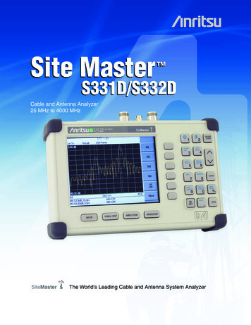
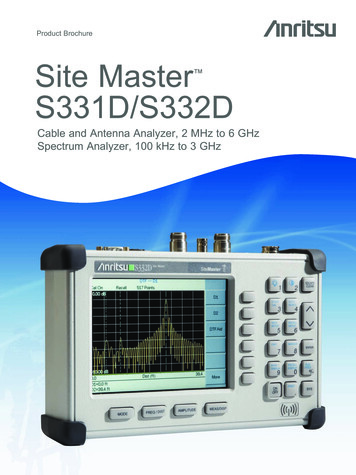
5. Power Monitor Verification (Option 5)The following test can be used to verify the accuracy of the power monitor function.a. Equipment Required:· Anritsu MG3692A Synthesized Signal Source, with options 2A, 4 and 15A· Anritsu ML2438A Dual Channel Power Meter or equivalent· Anritsu MA2442D High Accuracy Power Sensor or equivalent· Anritsu 34NN50A 50 Ohm adapter or equivalent· Anritsu 34RKNF50 50 Ohm adapter or equivalent· Anritsu 15NN50-1.5C RF Coaxial Cable or equivalent· Anritsu 560-7N50B N Type RF Detector· Aeroflex/Weinschel 1870A Power Splitterb. Procedure:1. Turn on the power meter and signal source.NOTE: Before continuing, allow a five minute warm up for the internal circuitry to stabilize.2. Set the MG3692A output power level to 5 dBm.3. Set the MG3692A output to 1 GHz CW.4. Connect the power sensors to the power meter and calibrate the sensors.5. On the power meter, press the Sensor key, the Cal Factor soft key, and then the FREQ soft key.Use the keypad to enter 1 GHz as the input signal frequency, which sets the power meter to theproper power sensor cal factor. Press the SENSOR key on the power meter to display the powerreading.6. Connect MG3692A, power meter, RF detector, Power Splitter and Power Sensor as shown in Figure OLD /-PRINT.SYSMEAS/DISPML2437A POWER METERFigure 1.Power Monitor Verification SetupSite Master MM3
7. Connect the external power supply (Anritsu part number 40-187-R) to the Site Master.8. On the Site Master, press and hold the ESCAPE/CLEAR key, then press the ON/OFF key to turn onthe Site Master. (This sets the instrument to the factory preset state.)9. Press the MODE key. Use the Up/Down arrow key to highlight Power Monitor and then pressENTER.10. On the MG3692A press the Level key, then use the knob to adjust the power level so that thepower meter reads -40 dBm.11. Verify that the Site Master reading is -40 dBm 1.0 dB.12. Repeat steps 10 and 11 for the other power level settings shown in Table 1.Table 14Power Monitor Test LevelsPower In @ 1 GHzSpecification0 dBm 1 dB-7 dBm 1 dB-21 dBm 1 dB-40 dBm 1 dBSite Master MM
6. Power Meter Verification (Option 29)The following test can be used to verify the accuracy of the power measurements.a. Equipment Required:· Anritsu MG3692A Synthesized Signal Source, with options 2A, 4 and 15A· Anritsu ML2438A Dual Channel Power Meter or equivalent· Anritsu MA2442A High Accuracy Power Sensor or equivalent· Anritsu N241A50 Power Splitter or equivalent· Anritsu 34NN50A 50W adapter or equivalent· Anritsu 34RSN50 50W adapter or equivalent· Anritsu 34RKNF50 50W adapter or equivalent· Anritsu 15NNF50-1.5C RF Coaxial Cable or equivalent· Aeroflex/Weinschel Model 44-10, 10 dB Fixed Attenuatorb. Procedure:1. Turn on the power meter and signal source.NOTE: Before continuing, allow a 30-minute warm up for the internal circuitry to stabilize.2. On the power meter, press the Channel key, the Setup soft key and then the CHANNEL soft key todisplay Channel 2 setup menu. Press the INPUT key twice to set the input configuration to B.Press the Sensor key to display both Sensor A and Sensor B Readings.3. Connect the power sensors to the power meter and calibrate the sensors.4. Set the MG3692A output power level to 5 dBm.5. Set the MG3692A output to 50 MHz CW.6. On the power meter, press the Sensor key, the Cal Factor soft key, and then the FREQ soft key. Usethe keypad to enter 50 MHz as the input signal frequency, which sets the power meter to theproper power sensor cal factor. Press the SENSOR key on the power meter to display the powerreading.7. Connect sensor A to the MG3692A output, measure the output power level and record the valuein column A of Table 2.Table 2.Output Power LevelAFreq (MHz)Sensor A Reading@ Source OutputBCDSensor A ReadingSensor B ReadingSplitter/Attenuator@ end of Attenu@ Power SplitterCombined LossatorOutputESensor B PathPower SplitterLoss50100020002850Site Master MM5
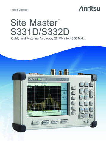
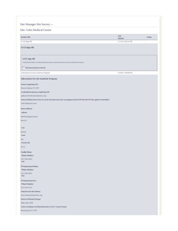
8. Disconnect Sensor A from the MG3692A output.9. Connect the power splitter to the MG3692A output and the Sensor B to one of the power splitteroutputs. Install the 10 dB Fixed Attenuator to the other power splitter output and then connectSensor A to the end of the Attenuator. Refer to Figure 2.F re q u e n c yC le a rE n tryB a c kS p a c eL e v e lS y s te m89456120L in eO u tp u t7M o d u la tio n3.O n O ff34RSN50ADAPTERR F O u tp u t5 0 9 /-O p e ra teS ta n d b yMG369XA SOURCE15NNF50-1.5CSENSOR BSENSOR AN241A50ATTENUATORABML2438A POWER METERFigure 2.Test Setup10. Record the new sensor A reading in column B of Table 2.11. Record Sensor B reading in column D of Table 2.12. Calculate the Splitter/Attenuator Combined Loss using the following formula and record the result in column C of Table 2: C A – B13. Calculate the Sensor B path Power Splitter Loss using the following formula and record the result in column E of Table 2: E A – D14. Repeat steps 10 through 13 for 1000 MHz, 2000 MHz and 2850 MHz.15. Calculate the desired Sensor B Reading for –30 dBm Test Power Level at the end of 10 dB attenuator using the following formula: Desired Sensor B Reading Test Power Level C – E16. Record the calculated results in Table 3.Table 3.–30 dBm Test Power LevelFreq (MHz)Desired Sensor B Reading for –30 dBm Input to Site Master501000200028506Site Master MM
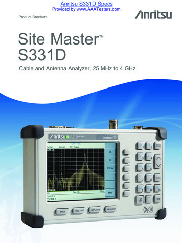
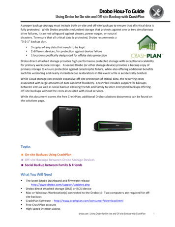
17. Using the power splitter, coaxial cable and adapters, connect the Site Master to the signal sourceand the power sensor as shown in Figure 3.ML2438A POWER METERMA2442AC le a rE n tryF re q u e n c yB a c kS p a c eL e v e lS y s te m89456120L in eO u tp u t7M o d u la tio n3.O n O ffR F O u tp u t5 0 915NNF50-1.5C /-N241A50O p e ra teS ta n d b yMG3692A SOURCE10 dBATTENUATOR34NN50AADAPTER34RSN50 UNHOLD /-PRINT.SYSMEAS/DISPS331DFigure 3.Power Meter Verification Setup18. Connect the external power supply (Anritsu part number 40-187-R) to the Site Master.19. On the Site Master, press and hold the ESCAPE/CLEAR key, then press the ON/OFF key to turn onthe Site Master. (This sets the instrument to the factory preset state.)20. Press the MODE key. Use the Up/Down arrow key to highlight Power Meter and then press ENTER.21. Press the Center soft key and enter 50, then press the MHz soft key to set the center frequency to50 MHz.22. Press the Span soft key and enter 3, then press the MHz key to set the span to 3 MHz.23. On the Power Meter, press the Sensor key and then the CalFactor soft key. Select the FREQ softkey and enter 50 MHz for the Input Signal Frequency. This sets the power meter to the properpower sensor cal factor. Press the Sensor key to display the power reading.24. Set the MG3692A output to 50 MHz CW and adjust the power level so that the power meter displays the corresponding desired Sensor B Reading for -30 dBm as recorded in Table 3.25. Verify that the Power Meter reading is within the specifications in Table 4.NOTE: If the reading is unstable, turn on RMS Averaging by pressing the MEAS/DISP key, then theRMS Averaging soft key. The number of points to average can be set to low, medium or high.Table 4.Power Meter AccuracySpecification for units withS/N 405039 and belowSpecification for units withS/N 405040 and above50–30 dBm 1 dB–30 dBm 1.5 dB1000–30 dBm 1 dB–30 dBm 1.5 dB2000–30 dBm 1 dB–30 dBm 1.5 dB2850–30 dBm 1.5 dB–30 dBm 1.5 dBFreq (MHz)Measured Value26. Repeat steps 22 and 25 for 1000 MHz, 2000 MHz, and 2850 MHz.Site Master MM7
7. T1/E1 Verification (Option 50)This procedure verify that the T1/E1 Tester of the Site Master is functioning properly.a. Equipment Required:· Tektronix TDS3032B Oscilloscope with option TDS 3TMT· Tektronix AFTDS D
Site Master MM i. 1. Introduction This manual provides maintenance instructions for the Site Master Model S331D Cable, Antenna and Base Station Analyzer. It describes the product and provides performance verification procedures, parts replacement procedures, and a replaceable parts list. 2. Description The Site Master is a handheld SWR/RL (standing wave ratio/return loss), Distance-To