Transcription
BASIC ELECTRONICSUNIT-1(10 Hours)Introduction to Electronics: Signals, frequency Spectrum of Signals, Analog and Digital Signals,Linear Wave Shaping Circuits: RC LPF, Integrator, RC HPF, Differentiator.Properties of Semiconductors: Intrinsic, Extrinsic Semiconductors, Current Flow in Semiconductors,Diodes: p-n junction theory, Current-Voltage characteristics, Analysis of Diode circuits, Rectifiers,Clippers, Clampers, Special diodesUNIT-II(14 Hours)Bipolar junction Transistor (BJTs): Physical Structures & Modes of Operation, TransistorCharacteristics, DC analysis, Introduction to Small Signal Analysis, Transistor as an amplifier, The RCcoupled amplifier, Introduction to Power Amplifiers, Transistor as switch.Field Effect Transistors (FETs): Physical Structures & Modes of Operation of MOSFETs, MOSFETCharacteristics, DC Analysis.Feedback Amplifiers & Oscillators: General Principles, Different types of feedback amplifier (blockdiagram only), Properties of Negative Feedback, Barkhausen criteria for Oscillation.Operational Amplifiers (OP-Amps): Ideal OP-AMP, Inverting Amplifier, Non-Inverting Amplifier.Adder, Subtractor, Integrator, Differentiator.UNIT-III(10 Hours)Digital Fundamentals: Binary Numbers, Signed-binary numbers, Decimal-to-Binary & Binary-toDecimal Conversion, Binary Addition, Subtraction, Multiplication and Division, Hexadecimal NumberSystems, Logic Gates, Boolean Algebra, De Morgan’s Theorems, Laws of Boolean Algebra, Basics ofFlip flops, Shift Resistors, Counters.UNIT-IV(10 Hours)Introduction to Electronic Instruments: CRO, Multimeter, Signal Generators.Principles of Communication: Fundamentals of AM & FM, Transmitters & ReceiversTEXT BOOKS:1. Microelectronics Circuits, A.S Sedra, K.C. Smith, Oxford University Press. Selected portions from chapters1to 5, 8, 13.2. Electronics Fundamentals and Applications, D Chattopadhyay and P.C. Rakshit, NewAge InternationalPublications. Selected portions from chapters 4 to 14, 16 to 20.REFERENCE BOOKS:1. Integrated Electronics, Millman and Halkias, Mc.Graw Hill Publications.2. Electronic Devices & Circuit Theory, R.L Boylestad and L. Nashelsky, Pearson Education
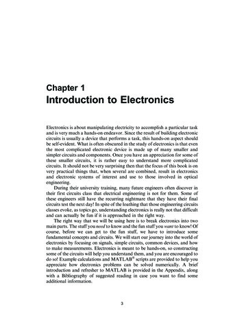
MODULE-IINTRODUCTION TO ELECTRONICS:Electronics is the branch of science and engineering dealing with the theoty anduse of a class of devices in which electrons are transported through a vacuum, gas orsemiconductor.Signals:It contains information about a variety of things and activities.Example - Voice of the radio announcer, weather informationAnalog Signal: The signal magnitude can be represented at any instant of time by asequence of numbers.Discrete Signal: It is a sequence of numbers that represent the magnitudes of thesuccessive signal samples.Digital Signal: Signal is in the form of 0 and 1.Frequency Spectrum of Signal:Any arbitrary signal is characterized by its frequency spectrum. The signal isrepresented in frequency domain.Fourier series: It is an expansion of periodic signal as a linear combination of sine andcosine with different frequencies and amplitudes. It is applied to periodic signals.Fourier transform: Fourier transform can be applied to aperiodic signals to find thefrequency spectrum.
Low Pass Filter:· Filter that passes low frequency components of a signal but rejects the highfrequency components of a signal is called as low pass filter.· Filters designed with passive components (Resistor, capacitor, inductor) arecalled as passive filters.Behaviour of capacitor to frequency can be described as followsFor f 0 (Low frequency) capacitive reactance of capacitor Xc V1 , So it I 2pfCacts as a open circuitFor f (High Frequency) capacitive reactance of capacitor Xc V1 0So it I 2pfCacts as a short circuitOperationFor low frequency since capacitor is open circuited, current flowing in thecircuit is zero. So the output voltage vout vinFor high frequency since capacitor is short circuited, the output voltage across ashort is zero So the output voltage vout 0The frequency response curve can be shown as below
Calculation of cutoff frequency:vout voutXC vinR XCXC vinR 2 XC 2If R XcVout 1 vin 0.707 vin2At the frequency of which R Xc, the output will be 70.7% of the input.1Xc R 2pfCCutoff frequencyfc 12pRCLPF as Integrator:· Output voltage (current) is directly proportional to the integration of the inputvoltage(current)· The time constant RC of the circuit should be very large as compared to the timeperiod of the input wave.· The value of R should be 10 or more times larger than Xc.For high frequencies the capacitor has insufficient to charge up, its voltage is small. Sothe voltage across the resistor is approximately equal to the input voltage.vin VRVR vini R RThe charge q on the capacitor at any instant isq ò idtoutput voltage vout vc q ò idt1 ò vindtCCRCHigh Pass Filter:· Filter that blocks low frequency components of a signal but passes the highfrequency components of a signal is called as high pass filter.· Filters designed with passive components (resistor, capacitor, inductor) are calledas passive filters.
OperationFor low frequency Since capacitor is open circuited, current flowing in thecircuit is zero. So the output voltage vout VR 0For high frequency since capacitor is short circuited, So the output voltagevout VR vinThe frequency response curve can be shown as belowCalculation of cutoff frequency:vout voutR vinR XCXC vinR 2 XC 2If R XcVout 1 vin 0.707 vin2At the frequency of which R Xc, the output will be 70.7% of the input.Xc R 12pfCCutoff frequencyfc 12pRCHPF as Differentiator:· Output voltage (current) is directly proportional to the differentiation of the inputvoltage(current)· The time constant RC of the circuit should be very small as compared to the timeperiod of the input wave.· The value of R should be 10 or more times smaller than Xc.For high frequencies the capacitor has enough time to charge up. So the voltage acrossthe capacitor is approximately equal to the input voltage.vin vc
The charge q on the capacitor at any instant isq C vcdqdvCdvioutput voltage vout iR R CR CRdtdtdtSemiconductor:· Conductivity lies between conductor and insulator.· Forbidden energy gap 0.2-2.5eV.· At 0K a pure semiconductor behaves as an insulator.· Semiconductor materials show a reduction in resistance with increase intemperature. So said to have a negative temperature coefficient.Intrinsic Semiconductor:· Semiconductor refined to reduce the number of impurities to a very low level.e.g : Semiconductor in pure form· Group-IV elements. Si, Ge,Extrinsic Semiconductor:· To increase the conductivity, impurities also called dopant (Group III or V) areadded to the pure semiconductor material and is called extrinsic Semiconductor(n-type or p-type). The process is called doping.· N-type Semiconductor- Pentavalent (As,Sb,P) atom is added to puresemiconductor. Diffused impurities with five valence electrons are called donoratoms.· P-type Semiconductor- Trivalent (Al,B,Ga) atom is added to puresemiconductor. Diffused impurities with three valence electrons are calledacceptor atoms.
· Holes are the majority carrier in p-type semiconductor and electrons areminority carrier. In n-type semiconductor electrons are the majority carrier andholes are the minority carrier.Diode:· Solid state device created by joining the p-type and n-type material is called assemiconductor diode.No Bias (V 0)· Absence of external voltage across the p-n junction is called the unbiased diode.Because of the density gradient electrons and holes diffuse and they combineleaving the ions unneutralised and are called uncovered charges.· The uncovered charges generate an electric field directed from n-side to p-sidecalled as barrier field which opposes the diffusion process further.· Since the vicinity of the junction is depleted of mobile charges. Hence called a asdepletion region.
Reverse Bias (V D 0V)· Positive polarity of the external bias V D is connected to n-type andnegative terminal is connected to p-type.· The number of uncovered positive and negative ions will increase in thedepletion region causing widening the depletion region which creates agreat barrier for the majority carrier to overcome, effectively reducingthe majority carrier flow to zero and hence the current due to majoritycarrier Imajority 0· The minority carriers which travels down the potential barrier remainunaffected and give a small current called the reverse saturation currentdenoted as Is.Forward Bias (V D 0V)· Positive polarity of the external bias V D is connected to p-type and negativeterminal is connected to n-type.· External bias V D exerts a force on the mobile carriers to move them towards thejunction. At the boundary they recombine with the ions and reduce the width ofthe depletion region.· The depletion region will continue to decrease in width as the voltage is increasedfurther and a heavy flood of electrons will move from n-side to p-side giving theImajority an exponential rise from p-side to n-side,· The minority carrier flow will not be affected by this because the conduction levelis determined by the limited number of impurities in the material and the current is
denoted by Is.The total current is given byID IForward IReverse Imajority - Iminority (Direction opposite)In terms of reverse saturation current, ID can be written aseVID Isexp()-Is is called the Shockley’s equation.hKTWheree- Charge of an electronK-Blotzman’s ConatantT-Temperature in Kelvinη- Quality factor depends upon the diode material (η 2 for Si and 1 for Ge)V- Supplied voltage across the junctionBreakdown Condition:(a) Zener Breakdown· Too much of reverse bias across a p-n junction exert a strongforce on a bound electron to tear it out from the covalent bond.Thus a large number of electron and hole pair will be generatedthrough a direct rupture of the covalent bonds and they increasethe reverse current and gives sharp increase in the characteristics.It is called zener breakdown. Diode employing the uniqueportion of the characteristics of a p-n junction is called zenerdiode.· Maximum reverse voltage potential that can be applied beforeentering the zener region is called the peak inverse voltage (PIV)or peak reverse voltage (PRV).
(b) Avalanche Breakdown:· With increasing reverse bias voltage, the electric field across thejunction of a diode increases. At a certain value of the reversevoltage, the electric field imparts a sufficiently high energy to athermally generated carrier. The carrier on colliding with an ionon its way disrupts a covalent bond and gives a new hole electronpair. This process is cumulative and gives an avalanche ofcarriers in a very short time. It is called avalanche multiplication.Diode equivalent Circuit:· Equivalent circuit is a combination of element properly chosen tobest represent the actual terminal characteristics of a device orsystem in a particular operating point.Ideal diode in forward and reverse biased condition is as follows
Diode Resistance levels:· According to the applied signal the resistance levels in a diode hasfollowing type1. DC or Static (DC signal)2. AC or Dynamic(Small AC signal)3. Average ac( Large AC signal)
CLIPPERIt controls the shape of the output waveform by removing or clipping a portion of theapplied wave. Half wave rectifier is the simplest example.It is also referred asvoltage limiters/ amplitude selectors/ slicers.Applications:· In radio receivers for communication circuits.· In radars, digital computers and other electronic systems.· Generation for different waveforms such as trapezoidal, or squarewaves.Helps in processing the picture signals in television transmitters.· In television receivers for separating the synchronizing signals fromcomposite picture signalsTypes of Clipper Circuit1. Series- Diode is in series with the source2. Parallel- Diode is in parallel with the source.· Clipper circuit which uses a DC battery is called a biased clipper.SERIES CLIPPER:Assumption- diode is ideal in characteristicsAnalysis ve Half Cycle:Diode is on because of forward biasing condition.Since no voltage drop across the diode the outputvoltage becomesVO VR Vi-ve Half Cycle:Diode is off because of reverse biasing condition.Since no current flows through the circuit the outputvoltage VO 0.Figure shows the output waveform of a simple series clipper with input as square andtriangular waveform. Since the negative half cycle is clipped off in the output it is calledas a negative clipper circuit.
Biased Series Clipper:Assumption- diode is ideal in characteristicsAnalysisSince the diode is on because of the 5v batteryThe transition of the diode from one state toanother can be found out to be atVi -5v abovewhich the diode is ON and below which thediode is OFF. ve Half Cycle:Since the diode is on the output voltage willbe (Applying KVL)Vi 5 VRVO Vi 5-ve Half Cycle:Since the diode is off VO 0.Figure Shows the input and output waveform.Example of Other Series Clipper Circuits:
PARALLEL CLIPPER:Assumption- diode is ideal in characteristicsAnalysis ve Half Cycle:Diode is on because of forward biasing condition.Since no voltage drop across the diode the outputvoltage becomesVO Vd 0-ve Half Cycle:Diode is off because of reverse biasing condition.Since no current flows through the circuit the output voltage VO Vi.Figure shows the output waveform of a simple parallel clipper with input as square andtriangular waveform. Since the positive half cycle is clipped off in the output it is calledas a positive clipper circuit.Biased parallel Clipper:Assumption- diode is ideal in characteristicsAnalysisThe transition of the diode from one state toanother can be found out to be atVi 4v abovewhich the diode is OFFand below which thediode is ON. ve Half Cycle:Since the diode is OFF (above 4v) the outputvoltage will be (Applying KVL)Vi VO-ve Half Cycle:Since the diode is ON (below 4v)VO 4v.Figure Shows the input and output waveform.
Example of Other Parallel Clipper Circuits:CLAMPERS:· A diode and capacitor can be combined to “clamp” an AC signal to a specific DClevel.· It must have a capacitor, a diode and a resistive element.· For additional shift an independent DC supply can be introduced in the circuit.· The time constant τ RC must be large enough to ensure that the voltage acrossthe capacitor does not discharge significantly during the diode is nonconducting.Procedure to analyze a clamper circuit1. Consider the part of the input signal that will forward bias the diode.
2. During the On state assume that the capacitor will charge up instantaneously to avoltage level determined by the network.3. Assume that during the diode is in OFF sate the capacitor will hold on to itsestablished voltage level.4. The polarity of Vo must be same throughout the analysis.5. Total swing of the total output must match the swing of the input signal.-ve clamper analysis:-Diode is ON(Short Circuit) in the positive half cycle.- Established voltage level on the capacitorVc V-During negative half cycle the diode is OFF and theoutput voltage isVo VR -Vi-Vc -2V-Total swing of output is -2V which is same as the totalswing of the input.Biased Clamper Circuit:-ve half cycle:Diode is ON (S.C). So applying KVL around the inputloop we have-20 Vc 5 0Vc 25v and Vo 5vDuring ve half cycle diode is OFF. Applying KVLaround the outside loop we have10 25-Vo 0Vo 35v
Summary of the Clamper Circuit:RECTIFIERSAn important application of “regular” diodes is in rectification circuits. Thesecircuits are used to convert AC signals to DC in power supplies.A block diagram of this process in a DC power supply is shown below.
Half-Wave Rectifier:The above circuit is called as a Half-wave rectifier since it will generate a waveformvothat will have an average value of particular use in the ac-to-dc conversion process.During 0- (Positive Half Cycle) the diode is ON. Assuming an ideal diode with novoltage drop across it the output voltage vo will bevo VR V mDuring -T(Negative Half Cycle) the diode is OFF(Open Circuit). So the current flowingthrough the circuit will be 0. The output voltage vo will bevo VR i x R 0Figure shows the input and output waveform with outputVdc 0.318V m.
Disadvantage:1. The ac supply delivers power only half the time.2. Pulsating current frequency is equal to the supply frequency.Full wave Rectifier:The full wave rectifier utilizes both the positive and negative portions of the inputwaveform. Types of full wave rectifier are(a) Centre tapped configuration(b) Bridge configurationCentre tapped configuration:· Current flows through the load resistance in the same direction during the fullcycle of the input signal.· Centre tap transformer is used with the secondary winding. ve Half Cycle:· Diode D1 is short circuited and D2 is open circuited. Current flows through theupper half of the secondary winding.
-ve Half Cycle:· Diode D2 is short circuited and D1 is open circuited. Current flows throughthe lower half of the secondary winding.Complete input and output waveform can be shown asWhile this full-cycle rectifier is a big improvement over the half-cycle, thereare some disadvantages.Disadvantages:· It is difficult to locate the centre tap on the secondary winging.· The diodes must have high PIV.BridgeRectifier:The bridge rectifier uses four diodes connected in bridge pattern.
The operation ofthe bridge rectifier can be summarized as: ve Half Cycle:· Diode D1 and D3 are short circuited and D2 and D4 are open circuited.Current flows through D1 and D3 to give the output voltage across theresistor.-ve Half Cycle:· Diode D1 and D3 are open circuited and D2 and D4 are short circuited.Current flows through D2 and D4 to give the output voltage across theresistor.Complete input and output waveform can be shown asAdvantages:· No centre tapped transformer is required.· PIV is less.Disadvantages:· It requires four diode and the power loss in the rectifier element is more.
MODULE-IITRANSISTOR:1. Bipolar Junction Transistor (BJT)2. Field Effect Transistor (FET)Bipolar Junction Transistor (BJT):······pnp-- n-type semiconductor is sandwiched between two p-type semiconductor.npn-- p-type semiconductor is sandwiched between two n-type semiconductor.It has three terminal naming E-Emitter, B-Base and C-Collector.Both electron and hole responsible for the current conduction. So called bipolar junctiontransistor.Doping wise-Emitter Collector BaseTwo Junctions- JEB (Junction emitter base) and JCB (Junction collector base).Transistor Operation:···JEB is forward biased by the battery VEE by which the depletion region will decrease and amajority carrier flow will occur from emitter to base giving current Imajority or IE.JCB is reverse biased by the battery VCC by which the depletion region will increase and aminority carrier flow will occur from base to collector giving current Iminority.When both the battery supplies are given simultaneously the holes in the base region dueto the battery VEE will act as minority carrier. They will cross the base region to reach thecollector giving the current IC.So the current equations of BJT can be written asIE IC IBIC Imajority IminorityIC α IE ICOWhere α is defined as the fraction of the total emitter current that represents holes whichhave travelled from emitter across the base to the collector and ICO is called as leakagecurrent.
·Depending upon the common terminal between input and output circuit of a transistor itmay be operated in 3 modes of a BJT(a) Common Base(b) Common Emitter(c) Common CollectorCommon Base:·InputDepending upon the biasing of the JEB and JCB, transistor has three region of operation.ApplicationJEBJCBRegion ofoperationON SwitchForward Bias Forward Bias SaturationForward BiasReverse BiasActiveAmplifierReverse BiasReverse BiasCutoffOFF SwitchCharacteristics: The plot of the input current against the input voltage with theoutput voltage as a parameter for a particular region of operation(Active).··Graph is plotted between input voltage VBE and current IEkeeping output voltage VCB as a parameter.The current variation with the emitter to base voltage issimilar to the forward characteristics of a p-n junction diode. However an increase in themagnitude of the collector to base voltage causes the emitter current to increase for afixed VBE because of the early effect or base width modulation.Output Characteristics: The plot of the output current against the output voltage with the inputcurrent as a parameter.·Graph is plotted between output voltage VCB andoutput current IC keeping input current IE as aparameter.
···Active Region:In this region JEB is forward biased and JCB is reverse biased. The collector current isindependent of VCB. It depends only on the emitter current IE.IC Imajority IminorityIC α IE ICBOWhere ICBO (also noted as ICO) is the leakage current called as collector to base leakagecurrent when emitter is open. Since this current is very small in magnitude IC IE.Cut off Region:Here both the junctions are reverse biased. The region below IE 0 characteristic iscalled as cut off region. In this region IC ICBO and in the range of nano amperes.Saturation Region:Here both the junctions are forward biased. The region is to the left of the graph whereVCB is slightly positive and IE 0.It gives an exponential variation in the collectorcurrent.JCB is forward biased means collector is positive with respect to base. It gives riseto a hole current flowing from collector to base and is opposite to the original flow due tothe transistor action. Output resistance of CB is very high because a very large change incollector voltage cases a very small change in collector current.CB Current Amplification Factor:It is the ratio of output collector current to the input emitter current.DC current gainAC current gainadc ICIEaac α 1 (Practically 0.9 to 0.998)DICwith VCB constantDIECommon Emitter:Here emitter terminal is common between the base and the collector.
Input Characteristics:··Graph is plotted between input voltage VBE and inputcurrent IB keeping output voltage VCE as a parameter.Characteristics are similar to that of a forward biaseddiode. For a constant VBE the magnitude of the basecurrent decreases. With increasing VCE. This is becauseincreasing VCE the effective base width and hence therecombination base current decreases.Output Characteristics:····Graph is plotted between output voltage VCE andoutput current IC keeping input current IB as aparameter.Active Region:In this region JEB is forward biased and JCB isreverse biased. Output characteristics in the activeregion are not horizontal lines because for a fixedvalue of IB the magnitude of collector currentincreases with VCE due to early effect.IC α IE ICBO (CB) α( IE IE) ICBOIC α/(1- α) IB ICBO/(1- α)IC βIB ICEOSince the leakage current ICEO is very small IC βIBCut off Region:Here both the junctions are reverse biased. The region below IB 0 characteristic iscalled as cut off region. In this region IC ICEO (Collector to emitter leakage current withbase open)Saturation Region:Here both the junctions are forward biased by at least the cutin voltage. The current ICis independent of IB.CE Current Amplification Factor:It is the ratio of output collector current to the input baser current.DC current gainAC current gainb dc ICpractically 50-400IBb ac DICwith VCE constantDIB
Relation between α and :a IE IC IBICa IC ICandIEICba b ICIBb1 bb a1-aDC Biasing:Biasing is the application of external dc supply to establish a fixed level of current andvoltage. Transistor operates only at a particular point of the characteristics called operating pointor Q-point/ Quiescent point.Types of Biasing1.2.3.4.Fixed Bias ConfigurationFixed bias with emitter resistorVoltage divider bias configurationCollector feedback configurationFixed Bias Configuration:It is the simplest transistor DC bias configuration using npn transistor. In the DC analysiscapacitors are open circuited as shown in the figure.
Base Emitter Loop:Applying KVL wehaveVCC-IBRB-VBE 0I B VCC - VBERBSince VBE and VCC are constant, the selection of a base resistor RBsets the level of base current for the operating point.Collector Emitter Loop:I C b I BVCC-ICRC-VCE 0VCE VCC-ICRCSo RB controls IB and IC, and the level of RC determines themagnitude of VCE.VCE VC- VE VBE VB- VEFixed Bias with emitter resistor Configuration:It contains an emitter resistor to improve the stability level over fixed bias.Base Emitter Loop:Applying KVL wehaveVCC-IBRB-VBE- IERE 0
IB VCC - VBERB ( b 1) RECollector Emitter Loop:I C b I BVCC-ICRC-VCE- IERE 0VCE VCC-IC (RC RE)Voltage divider bias Configuration:In the previous bias configurations the Q-points were dependent on β which is temperaturesensitive. Voltage divide bias arrangement reduces the dependency ob β.Exact Analysis:The input side can be solved by Thevenin equivalent circuit.For thevenin equivalent resistance the input dc source is shortcircuited.RTH R1R 2R1 R 2For thevenin equivalent voltage the source VCC is returned tothe circuit and the voltage is given by
VTH VR2 VCCR 2R1 R 2The Thevenin equivalent circuit is redrawn and the IBQ canbe found by applying KVLVTH-IBRTH-VBE-IERE 0I B VTH - VBERTH ( b 1) REBy solving the output collector emitter loop by KVLVCE VCC-IC (RC RE)Collector feedback configuration:An improved level of stability can be obtained by providing a feedback path.Base Emitter Loop:Applying KVL and solving we haveI B VCC - VBERF b ( RC RE )Collector Emitter Loop:Applying KVL and solving we haveVCE VCC-IC (RC RE)
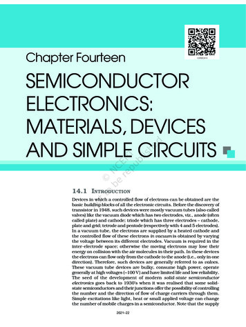
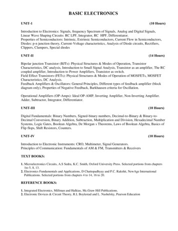
Field-Effect TransistorsINTRODUCTIONThe field-effect transistor (FET) is a three-terminal device used for a variety of applications thatmatch, to a large extent, those of the BJT transistor. JFET transistor is a voltage-controlleddevice. For the FET the current ID will be a function of the voltage VGS applied to the inputcircuit. The FET is a unipolar device depending solely on either electron (n- channel) or hole ( p-channel) conduction.The term field effect in the name deserves some explanation. We are all familiarwith the ability of a permanent magnet to draw metal filings to itself without the need for actualcontact. The magnetic field of the permanent magnet envelopes the filings and attracts them to themagnet along the shortest path provided by the magnetic flux lines. For the FET an electric fieldis established by the charges present, which controls the conduction path of the output circuitwithout the need for direct contact between the controlling and controlled quantities.FIG. 1voltage-controlled amplifiers.Comparison of some of the general characteristics of BJT with FET:One of the most important characteristics of the FET is its high input impedance.The variation in output current is typically a great deal more for BJTs than for FETs for the samechange in the applied voltage.FETs are more temperature stable than BJTs, and FETs are usually smaller than BJTs, makingthem particularly useful in integrated-circuit (IC) chips.The construction characteristics of some FETs, however, can make them more sensitive tohandling than BJTs.Type of FET:Three types of FETs : the junction field-effect transistor (JFET), the metal–oxide–semiconductor field-effect transistor (MOSFET), and the metal– semiconductor field-effecttransistor (MESFET). The MOSFET category is further broken down into depletion andenhancement types. The MOSFET transistor has become one of the most important devicesused in the design and construction of integrated circuits for digital computers. Its thermalstability and other general characteristics make it extremely popular in computer circuit design.
CONSTRUCTION AND CHARACTERISTICS OF JFETsJFET is a three-terminal device with one terminal capable of controlling the current betweenthe other two. The major part of the structure is the n-type material, which forms the channelbetween the embedded layers of p-type material. In the absence of any applied potentials theJFET has two p–n junctions under no-bias conditions. The result is a depletion region at eachjunction, as shown in Fig. 2 that resembles the same region of a diode under no-bias conditions.FIG. 2Junction field-effect transistor (JFET).VG 0 V, VDS Some Positive ValueA positive voltage VDS is applied across the channel and the gate is connected directly to thesource to establish the condition VGS 0 V .Under the conditions the flow of charge is relativelyuninhibited and is limited solely by the resistance of the n-channel between drain and source.The depletion region is wider near the top of both type materials. The current ID will establishthe voltage levels through the channel as indicated on the figure. The result is that the upperregion of the p-type material will be reverse-biased by about.As the voltage VDS is increased from 0 V to a few volts, the current will increase asdetermined by Ohm’s law and the plot of ID versus VDS. As VDS increases and approaches alevel referred to as VP , the depletion regions will widen, causing a noticeable reduction in thechannel width. The reduced path of conduction causes the resistance to increase. The morehorizontal the curve, the higher the resistance, suggesting that the resistance is approaching“infinite” ohms in the horizontal region. If VDS is increased to a level where it appears that thetwo depletion regions would touch” , a condition referred to as pinch-off will result.
FIG 3 JFET at VGS 0 V and VDS 7 0 VFIG 4 ID versus VDS for VGS 0 V.As VDS is increased beyond VP, the region of close encounter between the two depletion regionsincreases in length long the channel, but the level of ID remains essentially the same. In essence,therefore, once VDS 7 VP the JFET has the characteristics of a current source. As shown in Fig.5, the current is fixed at ID IDSS, but the voltage VDS (for levels 7 VP) is determined by theapplied load.The choice of notation IDSS is deriv
BASIC ELECTRONICS UNIT-1 (10 Hours) Introduction to Electronics: Signals, frequency Spectrum of Signals, Analog and Digital Signals, Linear Wave Shaping Circu