Transcription
ATME COLLEGE OF ENGINEERINGMYSURU-570028BASIC ELECTRONICSNOTES FOR 1st SEMESTERSUBJECT CODE: 18ELN14
VisionTo develop highly skilled and globally competent professionals in the field of Electronics andCommunication Engineering to meet industrial and social requirements with ethical responsibility.Mission To provide State-of-art technical education in Electronics and Communication atundergraduate and post-graduate levels, to meet the needs of the profession and society andachieve excellence in teaching-learning and research.To develop talented and committed human resource, by providing an opportunity forinnovation, creativity and entrepreneurial leadership with high standards of professionalethics, transparency and accountability.To function collaboratively with technical Institutes/Universities/Industries, offeropportunities for interaction among faculty-students and promote networking with alumni,industries and other stake-holders.Program outcomes (POs)Engineering Graduates will be able to:PO1. Engineering knowledge: Apply the knowledge of mathematics, science, engineeringfundamentals, and an engineering specialization to the solution of complex engineering problems.PO2. Problem analysis: Identify, formulate, review research literature, and analyze complexengineering problems reaching substantiated conclusions using first principles of mathematics,natural sciences, and engineering sciences.PO3. Design/development of solutions: Design solutions for complex engineering problems anddesign system components or processes that meet the specified needs with appropriate considerationfor the public health and safety, and the cultural, societal, and environmental considerations.PO4. Conduct investigations of complex problems: Use research-based knowledge and researchmethods including design of experiments, analysis and interpretation of data, and synthesis of theinformation to provide valid conclusions.PO5. Modern tool usage: Create, select, and apply appropriate techniques, resources, and modernengineering and IT tools including prediction and modelling to complex engineering activities withan understanding of the limitations.PO6. The engineer and society: Apply reasoning informed by the contextual knowledge to assesssocietal, health, safety, legal and cultural issues and the consequent responsibilities relevant to theprofessional engineering practice.PO7. Environment and sustainability: Understand the impact of the professional engineeringsolutions in societal and environmental contexts, and demonstrate the knowledge of, and need forsustainable development.
PO8. Ethics: Apply ethical principles and commit to professional ethics and responsibilities andnorms of the engineering practice.PO9. Individual and team work: Function effectively as an individual, and as a member or leaderin diverse teams, and in multidisciplinary settings.PO10. Communication: Communicate effectively on complex engineering activities with theengineering community and with society at large, such as, being able to comprehend and writeeffective reports and design documentation, make effective presentations, and give and receive clearinstructions.PO11. Project management and finance: Demonstrate knowledge and understanding of theengineering and management principles and apply these to one’s own work, as a member and leaderin a team, to manage projects and in multidisciplinary environments.PO12. Life-long learning: Recognize the need for, and have the preparation and ability to engage inindependent and life-long learning in the broadest context of technological change.Program Specific Outcomes (PSOs)At the end of graduation the student will be able, To comprehend the fundamental ideas in Electronics and Communication Engineering andapply them to identify, formulate and effectively solve complex engineering problems usinglatest tools and techniques. To work successfully as an individual pioneer, team member and as a leader in assortedgroups, having the capacity to grasp any requirement and compose viable solutions. To be articulate, write cogent reports and make proficient presentations while yearning forcontinuous self improvement. To exhibit honesty, integrity and conduct oneself responsibly, ethically and legally; holdingthe safety and welfare of the society paramount.Program Educational Objectives (PEOs) Graduates will have a successful professional career and will be able to pursue highereducation and research globally in the field of Electronics and Communication Engineeringthereby engaging in lifelong learning.Graduates will be able to analyse, design and create innovative products by adapting to thecurrent and emerging technologies while developing a conscience for environmental/ societalimpact.Graduates with strong character backed with professional attitude and ethical values willhave the ability to work as a member and as a leader in a team.Graduates with effective communication skills and multidisciplinary approach will be able toredefine problems beyond boundaries and develop solutions to complex problems of today’ssociety.
Academic Year: 2018 – 2019 (Odd Semester)Department: Electronics and Communication EngineeringCourse Code18ELN14ObjectivesCourse TitleCore/ElectivePrerequisiteContactHoursL TPTotal Hrs/SessionsBasicCore2240ElectronicsThis course will enable students to: Understand characteristics, operationandapplication sof the diodes, bipolarjunction transistors, field effect transistors, SCRs and operational amplifiers in electroniccircuits. Understand differentnumber systems andworking of fundamental buildingblocks of digital circuits. Understand theprincipleof basic communicationsystem andmobilephones.Topics Covered as per SyllabusModule -1: Semiconductor Diodes and Applications: p-n junction diode, Equivalent circuit of diode, Zener Diode,Zener diode as a voltage regulator, Rectification-Half wave rectifier, Full wave rectifier, Bridge rectifier, Capacitorfilter circuit (2.2, 2.3, 2.4 of Text 1).Photo diode, LED, Photocoupler. (2.7.4, 2.7.5, 2.7.6 of Text 1).78XX series and 7805 Fixed IC voltage regulator (8.4.4 and 8.4.5 of Text 1).Module -2: FET and SCR: Introduction, JFET: Construction and operation, JFET Drain Characteristics andParameters, JFET Transfer Characteristic, Square law expression for ID, input resistance, MOSFET: Depletion andEnhancement type MOSFET- Construction, Operation, Characteristics and Symbols, (refer 7.1, 7.2, 7.4, 7.5 of Text2),CMOS (4.5 of Text 1).Silicon Controlled Rectifier (SCR) – Two-transistor model, switching action, Characteristics, Phase controlapplication (refer 3.4 upto 3.4.5 of Text 1).Module -3: Operational Amplifiers and Applications: Introduction to Op-Amp, Op-Amp Input Modes, Op-AmpParameters-CMRR, Input Offset Voltage and Current, Input Bias Current, Input and Output Impedance, Slew Rate(12.1, 12.2 of Text 2).Applications of Op-Amp -Inverting amplifier, Non-Inverting amplifier, Summer, Voltage follower, Integrator,Differentiator, Comparator (6.2 of Text 1).Module-4: BJT Applications, Feedback Amplifiers and Oscillators: BJT as an amplifier, BJT as a switch, Transistorswitch circuit to switch ON/OFF an LED and a lamp in a power circuit using a relay (refer 4.4 and4.5 of Text 2).Feedback Amplifiers – Principle, Properties and advantages of Negative Feedback, Types of feedback, Voltageseries feedback, Gain stability with feedback (7.1-7.3 of Text 1).Oscillators – Barkhaunsen's criteria for oscillation, RC Phase Shift oscillator, Wien Bridge oscillator (7.7-7.9 of Text1).IC 555 Timer and Astable Oscillator using IC 555 (17.2 and 17.3 of Text 1).Module-5: Digital Electronics Fundamentals: Difference between analog and digital signals, Number SystemBinary, Hexadecimal, Conversion- Decimal to binary, Hexadecimal to decimal and vice-versa, Boolean algebra,Basic and Universal Gates, Half and Full adder, Multiplexer, Decoder, SR and JK flipflops, Shift register, 3 bit
Ripple Counter (refer 10.1-10.7 of Text 1).Basic Communication system, Principle of operations of Mobile phone (refer 18.2 and 18.18 of Text 1).List of Text Books1. D.P. Kothari, I.J. Nagarath, “Basic Electronics”, 2nd edition, Mc Graw Hill, 2018.2. Thomas L. Floyd, “Electronic Devices”, Pearson Education, 9th edition, 2012.List of Reference Books1. D.P. Kothari, I.J. Nagarath, “Basic Electronics”, 1st edn, McGraw Hill, 2014.2. Boylestad, Nashelskey, “Electronic Devices and Circuit Theory”, Pearson Education, 9th Edition, 2007/11thedition, 2013.3. David A. Bell, “Electronic Devices and Circuits”, Oxford University Press, 5th Edition, 2008.4. Muhammad H. Rashid, “Electronics Devices and Circuits”, Cengage Learning, 2014.List of URLs, Text Books, Notes, Multimedia Content, etc1. K A Navas, T A Suhail, “Basic Electronics” Rajath publishers2. http://nptel.ac.in/courses/117103063/3. c%20Electronics.pdfAfter studying this course, students will be able to:1. Describe the operation of diodes, BJT, FET and Operational Amplifiers.2. Design and explain the construction of rectifiers, regulators, amplifiers and oscillators.3. Describe general operating principles of SCRs and its application.Course4. Explain the working and design of fixed voltage IC regulator using 7805 and Astable oscillatorOutcomeusing Timer IC 555.s5. Explain the different number system and their conversions and construct simple combinationaland sequential logic circuits using Flip-Flops.6. Describe the basic principle of operation of communication system and mobile phones.Internal Assessment Marks: 40 (3 Session Tests are conducted during the semester and marks allotted based onaverage of best performances).
BASIC ELECTRONICS18ELN14/24MODULE 1SEMICONDUCTOR DIODE AND APPLICATIONSStructure1.1Introduction1.2P-N Junction Diode1.2.1 Diode Characteristics1.2.2. Diode Relationship1.3Equivalent circuit of Diode1.4Zener Diode1.5Zener Diode as a Voltage Regulator1.6Complement of Binary Numbers1.6.1. Half wave rectifier1.6.2 Full wave rectifier1.6.3 Bridge rectifier1.6.4. Capacitor filter Circuit1.7Photo Diode1.8LED1.9Photo Coupler1.1078XX series and 7805 Fixed IC voltage regulatorDept. of Basic Science & Humanities, ATMECEPage 1
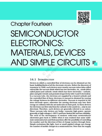
BASIC ELECTRONICS18ELN14/241.1 INTRODUCTIONDiode is an electrical component that allows the flow of current in only one direction. In circuitdiagrams, a diode is represented by a triangle with a line across one vertex.ANODECATHODE Diode has a wide range of applications like rectification (converting ac to dc), voltage regulation,protection against high voltage and wave shaping.There are special purpose diodes like Zener diode, LED- light emitting diode and several other.1.2 P-N JUNCTION DIODEWhen P-type and N-type silicon are placed in contact with one another it forms a PN junction. Atthis junction an interesting phenomenon occurs, one that is the foundation of solid-state electronics.Fig 1A basic PN junction creates a diode that allows electricity to flow in one direction. We can see inthe fig 1 that the N type material has free electrons shown as black dots and the P type material has holesshown as white dots.Fig 2Dept. of Basic Science & Humanities, ATMECEPage 2
BASIC ELECTRONICS18ELN14/24Near the PN junction the electrons diffuse into the vacant holes in the P material causing adepletion zone. This depletion zone acts like an insulator preventing other free electrons in the N-typesilicon and holes in the P-type silicon from combining as shown in fig 2.In addition, this leaves a small electrical imbalance inside the crystal. Since the N region ismissing some electrons it has obtained a positive charge. And the extra electrons that filled the holes inthe P region, have given it a negative charge. Unfortunately, one cannot generate power from thiselectrical imbalance. However, the stage is set to see how the PN junction functions as a diode.Fig 3In the fig 3 we have connected an external power source; a battery with a light and current meterthat indicate current flow. The negative terminal of the battery is connected to the N-type silicon. Likecharges repel, so the free electrons are pushed toward the PN junction. Similarly, the holes are repelled bythe positive terminal of the battery toward the PN junction. If the voltage pushing the electrons and holeshas sufficient strength to overcome the depletion zone (approximately 0.7 V for typical silicon diode) theelectrons and holes combine at the junction and current passes through the diode. When a diode isarranged this way with a power supply it is said to be forward-biased.Fig 4Dept. of Basic Science & Humanities, ATMECEPage 3
BASIC ELECTRONICS18ELN14/24In the fig 4 the battery is connected to the diode so that the negative terminal of the batteryconnects to the P-type silicon and the positive terminal of the battery connects to the N-type silicon. Thenegative terminal attracts the positive holes in the P-type silicon and the positive terminal of the batteryattracts the free electrons in the N-type silicon. All the charge carriers are pulled away from the PNjunction which essentially creates a larger depletion region and no current flows. When a diode isarranged this way with a power supply it is said to be reverse-biased.1.2.1. DIODE CHARACTERISTICSFig 5There are two operating regions and three possible “biasing” conditions for the standard Junction Diodeas shown in fig 5 and these are:1. Zero Bias – No external voltage potential is applied to the PN junction diode.2. Reverse Bias – The voltage potential is connected negative, (-ve) to the P-type material and positive,( ve) to the N-type material across the diode which has the effect of Increasing the PN junction diode’swidth.3. Forward Bias – The voltage potential is connected positive, ( ve) to the P-type material and negative,(-ve) to the N-type material across the diode which has the effect of Decreasing the PN junction diodeswidth.Dept. of Basic Science & Humanities, ATMECEPage 4
BASIC ELECTRONICS18ELN14/241.2.2. DIODE RELATIONSHIPID IS (where)Eq ----- 1IS reverse saturation currentk 11600/η; η 1 for Ge and η 2 for Si for low current, below the knee of the curveη 1 for both Ge and Si for higher level of current beyond the knee.TK TC 2730 where TC operating temperature (25oC).The plots of equation 1 for Ge and Si diodes are as shown in fig 6. The sharply rising part of the curveextended downward meets the VD axis, which is indicated as VT offset, threshold or firing potential.It is quite accurate to assume that ID 0 up to VT and then increases almost linearly at a sharp slope. Thevalue of VT is 0.7V for Silicon diode and 0.3 for Germanium diode.Fig 6 Diode CharacteristicsNOTE: ZENER REGION: When the diode is in the reverse bias condition at some point the reverse biasvoltage is so large that diode breaks down and the reverse current increases dramatically. Thismaximum voltage is called avalanche breakdown voltage and the current is called avalanchecurrent. The maximum negative voltage that a diode can withstand is at Peak Inverse Voltage(PIV rating). ZENER BREAKDOWN: By heavily doping the N and P Regions, the breakdown voltage Vz.can be brought as low as -10V, -5V. this mechanism of breakdown is different from avalanche.Dept. of Basic Science & Humanities, ATMECEPage 5
BASIC ELECTRONICS18ELN14/24This type of diode is called ZENER diode. When connected at a point in an electronic circuit, itdoes not allow the potential there to exceed the diode rated voltage.1.3 EQUIVALENT CIRCUIT OF DIODE1. Ideal diodeIt conducts when VD 0 as shown belowID0VDID -VDFig 72. Piecewise Linear diodeFig 8Dept. of Basic Science & Humanities, ATMECEPage 6
BASIC ELECTRONICS18ELN14/243. Dynamic ResistanceRD dVD / dI (average)It can be proved that dynamic resistance on any point of the actual IV characteristics of a diode isgiven by RD 26mV / dI (mA). The dynamic resistance of RD is quite small and order of fewohms.Fig 91.4 ZENER DIODEA Zener diode has Zener breakdown in reverse bias as shown in IV characteristics of fig below.The symbol of Zener diode is also shown.Fig 10Dept. of Basic Science & Humanities, ATMECEPage 7
BASIC ELECTRONICS18ELN14/241.5. ZENER DIODE AS A VOLTAGE REGULATORZener Diodes can be used to produce a stabilized voltage output with low ripple under varyingload current conditions. By passing a small current through the diode from a voltage source, via a suitablecurrent limiting resistor (RS), the Zener diode will conduct sufficient current to maintain a voltage dropof Vout.We remember from the previous tutorials that the DC output voltage from the half or full-wave rectifierscontains ripple superimposed onto the DC voltage and that as the load value changes so to does theaverage output voltage. By connecting a simple Zener stabilizer circuit as shown below across the outputof the rectifier, a more stable output voltage can be produced.Fig 11The resistor, RS is connected in series with the Zener diode to limit the current flow through the diodewith the voltage source, VS being connected across the combination. The stabilised output voltage Vout istaken from across the Zener diode. The Zener diode is connected with its cathode terminal connected tothe positive rail of the DC supply so it is reverse biased and will be operating in its breakdown condition.Resistor RS is selected so to limit the maximum current flowing in the circuit.With no load connected to the circuit, the load current will be zero, (IL 0), and all the circuit currentpasses through the Zener diode which in turn dissipates its maximum power. Also a small value of theseries resistor RS will result in a greater diode current when the load resistance RL is connected and largeas this will increase the power dissipation requirement of the diode so care must be taken when selectingthe appropriate value of series resistance so that the Zener’s maximum power rating is not exceeded underthis no-load or high-impedance condition.The load is connected in parallel with the Zener diode, so the voltage across RL is always the same as theZener voltage, (VR VZ). There is a minimum Zener current for which the stabilization of the voltage isDept. of Basic Science & Humanities, ATMECEPage 8
BASIC ELECTRONICS18ELN14/24effective and the Zener current must stay above this value operating under load within its breakdownregion at all times. The upper limit of current is of course dependent upon the power rating of the device.The supply voltage VS must be greater than VZ.One small problem with Zener diode stabilizer circuits is that the diode can sometimes generate electricalnoise on top of the DC supply as it tries to stabilize the voltage. Normally this is not a problem for mostapplications but the addition of a large value decoupling capacitor across the Zener’s output may berequired to give additional smoothing.Then to summarize a little. A Zener diode is always operated in its reverse biased condition. A voltageregulator circuit can be designed using a Zener diode to maintain a constant DC output voltage across theload in spite of variations in the input voltage or changes in the load current. The Zener voltage regulatorconsists of a current limiting resistor RS connected in series with the input voltage VS with the Zenerdiode connected in parallel with the load RL in this reverse biased condition. The stabilized output voltageis always selected to be the same as the breakdown voltage VZ of the diode.1.6. RECTIFICATION“Rectifiers are the circuit which converts ac to dc”. Rectifiers are grouped into two categories dependingon the period of conductions.1. Half-wave rectifier2. Full- wave rectifier.1.6.1. HALF-WAVE RECTIFIERThe circuit diagram of a half-wave rectifier is shown in Figure.1. 22 below along with the I/P and O/Pwaveforms.Figure 12 Half wave rectifier and its input output waveformsThe transformer is employed in order to step-down the supply voltage and also to prevent from shocks.The diode is used to rectify AC signal while, the pulsating DC is taken across the load resistor RL.During the ve half cycle, the end X of the secondary is ve and end Y is -ve. Thus, forward biasing thediode. As the diode is forward biased, the current flows through the load RL and a voltage is developedacross it.Dept. of Basic Science & Humanities, ATMECEPage 9
BASIC ELECTRONICS18ELN14/24During the –ve half-cycle the end Y is ve and end X is –ve thus, reverse biasing the diode. As the diodeis reverse biased there is no flow of current through RL thereby the output voltage is zero.1.6.2. THE FULL WAVE RECTIFIERIn the previous Power Diodes tutorial we discussed ways of reducing the ripple or voltage variations on adirect DC voltage by connecting capacitors across the load resistance. While this method may be suitablefor low power applications it is unsuitable to applications which need a “steady and smooth” DC supplyvoltage. One method to improve on this is to use every half-cycle of the input voltage instead of everyother half-cycle. The circuit which allows us to do this is called a Full Wave Rectifier.Like the half wave circuit, a Full Wave Rectifier Circuit produces an output voltage or current which ispurely DC or has some specified DC component. Full wave rectifiers have some fundamental advantagesover their half wave rectifier counterparts. The average (DC) output voltage is higher than for half wave,the output of the full wave rectifier has much less ripple than that of the half wave rectifier producing asmoother output waveform. In a Full Wave Rectifier circuit two diodes are now used, one for each half ofthe cycle. A multiple winding transformer is used whose secondary winding is split equally into twohalves with a common centre tapped connection, (C). This configuration results in each diode conductingin turn when its anode terminal is positive with respect to the transformer centre point C producing anoutput during both half-cycles, twice that for the half wave rectifier so it is 100% efficient as shownbelow.Full Wave Rectifier CircuitFigure 13. Center tap full wave rectifier and its input output waveformsDept. of Basic Science & Humanities, ATMECEPage 10
BASIC ELECTRONICS18ELN14/24The full wave rectifier circuit consists of two power diodes connected to a single load resistance (RL)with each diode taking it in turn to supply current to the load. When point A of the transformer is positivewith respect to point C, diode D1 conducts in the forward direction as indicated by the arrows.When point B is positive (in the negative half of the cycle) with respect to point C, diode D2 conducts inthe forward direction and the current flowing through resistor R is in the same direction for both halfcycles. As the output voltage across the resistor R is the phasor sum of the two waveforms combined, thistype of full wave rectifier circuit is also known as a “bi-phase” circuit.As the spaces between each half-wave developed by each diode is now being filled in by the other diodethe average DC output voltage across the load resistor is now double that of the single half-wave rectifiercircuit and is about 0.637Vmax of the peak voltage, assuming no losses.Where: VMAX is the maximum peak value in one half of the secondary winding and VRMS is the rmsvalue.The peak voltage of the output waveform is the same as before for the half-wave rectifier provided eachhalf of the transformer windings have the same rms voltage value. To obtain a different DC voltageoutput different transformer ratios can be used. The main disadvantage of this type of full wave rectifiercircuit is that a larger transformer for a given power output is required with two separate but identicalsecondary windings making this type of full wave rectifying circuit costly compared to the “Full WaveBridge Rectifier” circuit equivalent.1.6.3.THE FULL WAVE BRIDGE RECTIFIERAnother type of circuit that produces the same output waveform as the full wave rectifier circuit above, isthat of the Full Wave Bridge Rectifier. This type of single phase rectifier uses four individual rectifyingdiodes connected in a closed loop “bridge” configuration to produce the desired output. The mainadvantage of this bridge circuit is that it does not require a special centre tapped transformer, therebyreducing its size and cost. The single secondary winding is connected to one side of the diode bridgenetwork and the load to the other side as shown below.The Diode Bridge RectifierDept. of Basic Science & Humanities, ATMECEPage 11
BASIC ELECTRONICS18ELN14/24Figure 14 Full wave bridge rectifier and its input output waveformsThe four diodes labelled D1 to D4 are arranged in “series pairs” with only two diodes conducting currentduring each half cycle. During the positive half cycle of the supply, diodes D1 and D2 conduct in serieswhile diodes D3 and D4 are reverse biased and the current flows through the load as shown below.The Positive Half-cycleFig 15During the negative half cycle of the supply, diodes D3 and D4 conduct inseries, butdiodes D1 and D2switch “OFF” as they are now reverse biased. The current flowing through the load isthe same direction as before.The Negative Half-cycleFig 16Dept. of Basic Science & Humanities, ATMECEPage 12
BASIC ELECTRONICS18ELN14/24As the current flowing through the load is unidirectional, so the voltage developed across the load is alsounidirectional the same as for the previous two diode full-wave rectifier, therefore the average DC voltageacross the load is 0.637Vmax.Fig 17Typical Bridge RectifierHowever in reality, during each half cycle the current flows through two diodes instead of just one so theamplitude of the output voltage is two voltage drops ( 2 x 0.7 1.4V ) less than the inputVMAX amplitude. The ripple frequency is now twice the supply frequency (e.g. 100Hz for a 50Hz supplyor 120Hz for a 60Hz supply.Although we can use four individual power diodes to make a full wave bridge rectifier, pre-made bridgerectifier components are available “off-the-shelf” in a range of different voltage and current sizes that canbe soldered directly into a PCB circuit board or be connected by spade connectors.The image to the right shows a typical single phase bridge rectifier with one corner cut off. This cut-offcorner indicates that the terminal nearest to the corner is the positive or ve output terminal or lead withthe opposite (diagonal) lead being the negative or -ve output lead. The other two connecting leads are forthe input alternating voltage from a transformer secondary winding.1.6.4. THE CAPACITOR FILTER CIRCUITThe Smoothing CapacitorWe saw in the previous section that the single phase half-wave rectifier produces an output wave everyhalf cycle and that it was not practical to use this type of circuit to produce a steady DC supply. The fullwave bridge rectifier however, gives us a greater mean DC value (0.637 Vmax) with less superimposedripple while the output waveform is twice that of the frequency of the input supply frequency. We cantherefore increase its average DC output level even higher by connecting a suitable smoothing capacitoracross the output of the bridge circuit as shown below.Dept. of Basic Science & Humanities, ATMECEPage 13
BASIC ELECTRONICS18ELN14/24Full-wave Rectifier with Smoothing CapacitorFigure 18. Bridge rectifier with capacitor filter and its input output waveformsThe smoothing capacitor converts the full-wave rippled output of the rectifier into a smooth DC outputvoltage. Generally, for DC power supply circuits the smoothing capacitor is an Aluminum Electrolytictype that has a capacitance value of 100uF or more with repeated DC voltage pulses from the rectifiercharging up the capacitor to peak voltage.However, there are two important parameters to consider when choosing a suitable smoothing capacitorand these are its Working Voltage, which must be higher than the no-load output value of the rectifier andits Capacitance Value, which determines the amount of ripple that will appear superimposed on top of theDC voltage.Too low a capacitance value and the capacitor has little effect on the output waveform. But if thesmoothing capacitor is sufficiently large enough (parallel capacitors can be used) and the load current isnot too large, the output voltage will be almost as smooth as pure DC. As a general rule of thumb, we arelooking to have a ripple voltage of less than 100mV peak to peak.The maximum ripple voltage present for a Full Wave Rectifier circuit is not only determined by the valueof the smoothing capacitor but by the frequency and load current, and is calculated as:Bridge Rectifier Ripple VoltageWhere: I is the DC load current in amps, ƒ is the frequency of the ripple or twice the input frequency inHertz, and C is the capacitance in Farads.Dept. of Basic Science & Humanities, ATMECEPage 14
BASIC ELECTRONICS18ELN14/24The main advantages of a full-wave bridge rectifier is that it has a smaller AC ripple value for a givenload and a smaller reservoir or smoothing capacitor than an equivalent half-wave rectifier. Therefore, thefundamental frequency of the ripple voltage is twice that of the AC supply frequency (100Hz) where forthe half-wave rectifier it is exactly equal to the supply frequency (50Hz).The amount of ripple voltage that is superimposed on top of the DC supply voltage by the diodes can bevirtually eliminated by adding a much improved π-filter (pi-filter) to the output terminals of the bridgerectifier. This type of low-pass filter consists of two smoothing capacitors, usually of the same value anda choke or inductance across them to introduce a high impedance path to the alternating ripple componentAnother more practical and cheaper alternative is to use an off the shelf 3-terminal voltage regulator IC,such as a LM78xx (where “xx” stands for the output voltage rating) for a positive output voltage or itsinverse equivalent the LM79xx for a negative output v
Muhammad H. Rashid, “Electronics Devices and Circuits”, Cengage Learning, 2014. List of URLs, Text Books, Notes, Multimedia Content, etc 1. K A Navas, T A Suhail, “Basic Electronics” Rajath publishers .