Transcription
Arduino Uno Starter Kit12 example projects to getyou started with your Arduino.By: Tyson PopynickExclusively for Aus Electronics DirectThank you to Aus Electronics Direct for supplying me with the kit to make this book, my wifeHeidi, my son John and my daughter Cortana! I look forward to doing this again.
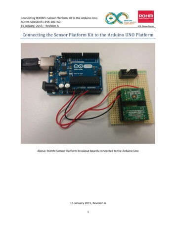
TitleAbout the ArduinoThe Arduino is an electronics prototyping device. It is essentially a microprocessor with built inserial debugging and USB programming in onedevice. It has many of the protections and safetyfeatures automatically taken care of, includingregulating the input power and all of the confusingfuse setting and what not is taken care of by thesoftware, leaving us with an easy to useprogramming language, and 1 click writing to theboard.Arduino essentially allows us to think of a project,and have a prototype up and running extremelyquickly. There are modules and “shields” availableto expand the abilities of your Arduino. A module isusually a component with its supporting circuitry already added, meaning you can simply plug itin as-is to the Arduino and with a few lines of code, get it working.A “shield” is an expansion for your Arduino that includes circuitry and often a new feature, suchas Wi-Fi or Ethernet, USB Host or motor drivers etc. They are generally shaped in such a waythat you can plug them in directly to the Arduino board, and they will have headers exposed atthe top to then plug your own components into.The board you have may be called an IDUINO or Arduino, or potentially other names also, this isbecause Arduino are open-source, allowing anyone to use their designs and plans freely. Therewill be no difference in operation between any of the differently named devices. The model I amusing is an IDUINO R3.I also have an Arduino and a duinotech Uno R3, and they are all identical.About the BreadboardIn your starter kit, you received a breadboard. (Pictured right).This breadboard has 2 long horizontal lines along the top andBottom of it, and then a series of holes throughout the middle.The midsection is connected vertically, with a break in theMiddle as shown on the right of the image. The top and bottomAre connected horizontally and are for power distribution.Feel free to google the breadboard for more information!Date1
TitleContentsAbout the Arduino . 1About the Breadboard. 1Contents . 2Before we begin . 3Installation & setup . 4Programming Basics . 5Project 1 – Serial Output . 6Project 2 – PWM (Pulse-Width Modulation) . 7Project 3 – Light Sensor (Photoresistor) . 10Project 4 – Flame Sensor . 12Project 5 – Remote . 14Project 6 – Tilt Sensor . 16Project 7 – RGB LED Control . 18Project 8 – Read a potentiometer . 20Project 8 – 7 Segment Display . 22Project 10 – Passive Buzzer . 29Project 10 – Active Buzzer . 31Project 12 – Buttons . 33Project 13 – LM35 Temperature Sensor. 35Date2
TitleBefore we beginBefore we begin downloading and installing yourArduino, let me begin by talking about the software wewill be using.IDE (Integrated Development Environment) is thesoftware we will use to program the Arduino. Ittranslates the code we write into the commands theArduino expects.It also includes a serial monitor, serial logger and otheruseful tools and examples.We will be making good use of the Serial Monitor in thisguide. Remember, any text you see in the serial monitorwas made and sent through the USB cable FROM theArduino to the computer.This guide is an introduction to the Arduino, it covers most of the components and modules youwill find in your starter kit, and includes the code needed to get them all working. You are freeto use and modify the code in your own projects, so you have a solid starting point. If you decideto expand your collection of modules later, be sure to shop with Aus Electronics Direct in orderto get a guide like this for each additional component!Date3
TitleInstallation & setupFirst, we must download the latest version of theArduino IDE. Please navigate to the following URL:https://www.arduino.cc/en/Main/SoftwareFollow the steps below to download and install thesoftware and drivers for your Arduino PrototypingBoard:1. Run the Arduino installer.2. Install with all the pre-selected options, there is no need to adjust anything here.3. Once the software has installed, plug the USB Cable that came with your kit into thecomputer, leaving the other end disconnected for the moment.4. Now you can remove your Arduino from the anti-static bag it was shipped in. This smallbag can be discarded or kept, it is up to you. The Arduino will not need it any longer,however it will not do it any harm if you decide to store it in there.5. At this point you should have the Arduino IDE installed. There should be a shortcut onyour desktop that looks like a blue circle with a white infinity symbol in it. You shouldalso have the Arduino board in front of you and the USB cable plugged in to thecomputer.6. Plug the USB cable into the Arduino. You should see some lights illuminate on theboards, and your computer may chime to say it has found the board.7. Run the Arduino software, we have 2 settings to verify, then we can dive in to the firstproject!8. In the Tools menu, please verify that next to Board: is “Arduino / Genuino Uno”. If this isnot selected please select this option now.9. And finally, click the Tools menu again, this time clicking PORT: and selecting the portwith an associated Arduino as shown below:Date4
TitleProgramming BasicsThe scariest thing to newcomers is the fact thatyou have to “program” the Arduino. This soundsmuch scarier than it really is. That is the beautyof Arduino. There is a team of people involved inmaking the Arduino as easy to use as possible,they do this by use of an abstraction layer,which takes somewhat easy to read andunderstand code, and allows it to run on theprocessor.Code essentials:Every Arduino sketch (Sketch is the Arduinoword for "program") REQUIRES the 2 basicfunctions:void setup() {// put your setup code here, to run once:}void loop() {// put your main code here, to run repeatedly:}A few notes about the functions. "void" tells the Arduino this function will not return any data, it will simply run when called. Functions are cAsE-SENsitIVE. Setup() is not the same as setup() or sEtup(). The Arduino runs the code in a set order. setup will be run first, once setup() is finishedrunning it will execute loop() repeatedly until you power it down. The brackets immediately after the function name are for any data that needs to be passed.setup() and loop() do not make use of this, however we still need to put the emptybrackets. The curly braces {} tell each function where they start and stop. Always make sure your codefalls inside these brackets Each function call/command/instruction MUST end in a semicolon ";". Finally, "//" tells the compiler to ignore the line, this is useful for writing comments in thecode that you can read, but wont affect the program itself.Date5
TitleProject 1 – Serial OutputExpected outcome:You will learn how to upload code to theArduino, as well as receive communication backthrough the USB cable.What you need: Arduino Prototype BoardThe Circuit:In this project we will not be connecting anythingto our Arduino, simply executing code andviewing the result.The Code://----Begin Code (copy from here)---//Variablesvoid setup() {// put your setup code here, to run once:Serial.begin(9600); //Opens the Serial port and sets the data rateSerial.print("Serial Started.\nHello World!!"); //Prints the string of text to the serial monitor.//Note - You must enclose strings of text in "" quotes. Otherwise Arduino will think you aretalking about a variable.}void loop() {// put your main code here, to run repeatedly:}//----End Code (copy to here)----Try it out:1. Press the “Upload Code” button in the IDE.2. If the Serial Monitor window is not open, open as follows:Tools Menu - Serial Monitor.Change the text inside the quotes in the Serial.print(“.”); function call, then re-upload the code.Remember, the Arduino is sending this text to your computer, your computer is only displayingit!Date6
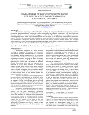
TitleProject 2 – PWM (Pulse-Width Modulation)Expected outcome:You will know what PWM is, and see its effectson an LED. You will build your first circuit of theseries also!What you need: Arduino Prototype BoardBreadboard and Jumper Wires1x 1K Resistor (Brown, Black, Black, Brown, Brown)Jumper WiresThe Circuit:Note: The LED will not be damaged if it is placed in backwards, however it will not light until it is swapped to thecorrect direction.When you connect the LED, take note there is a “flat” side in the ring around the base, as well as one longer and oneshorter leg. The flat side, and the shorter lead are to show the Cathode, or the NEGATIVE lead. This goes to the – or theBlack wire from the Arduino in the image above.The rounder side, with the longer lead is the Anode, or the POSITIVE lead. This goes to , or in this case, theArduino pin 6. We will set the pin to put out our Pulse-Width Modulated signal on this pin, and view itseffects on the LED.Date7
TitleThe Code://----Begin Code (copy from here)---//Variablesint ledPin 6; //This is a variable. We will discuss this after the code segment!int pwmVal 255; //PWM range is 0 - 255. Change this value and reupload to see thedifference!void setup() {// put your setup code here, to run once:pinMode(ledPin, OUTPUT); //Set the pin we chose above as OUTPUT.}void loop() {// put your main code here, to run repeatedly:analogWrite(ledPin, pwmVal); //analogWrite is the arduino function for PWM. We are tellingthe Arduino to apply a PWM signal to ledPin, with the value of pwmVal which we set at the topof this code.}//----End Code (copy to here)----Variables:Variables are like containers. You name them, and tell Arduino what type of values or data willbe stored.and it keeps track of what’s in there.In this project we used variables to give names to values we would be using later. This is handyto allow easy changing of values in one place, rather than searching the whole sketch for thevalues.Try it out:Go ahead and click the upload buttonAlternate Code:In addition to the above code, I am including this additional code for you to try. Open the SerialMonitor like we did in the first project and you will be able to watch as the PWM values dropand the LED gets dimmer, and as they rise it gets brighter.Date8
Title//----Begin Code (copy from here)---//Variablesint ledPin 6; //This is a variable. We will discuss this after the code segment!int pwmVal 255; //PWM range is 0 - 255. Change this value and reupload to see thedifference!int currVal 0;String serialOut "Current Value: ";void setup() {// put your setup code here, to run once:pinMode(ledPin, OUTPUT); //Set the pin we chose above as OUTPUT.Serial.begin(9600); //Open serial port}void loop() {// put your main code here, to run repeatedly:analogWrite(ledPin, pwmVal); //analogWrite is the arduino function for PWM. We are tellingthe Arduino to apply a PWM signal to ledPin, with the value of pwmVal which we set at the topof this code.if (pwmVal 0) { //If value is 0pwmVal 255; //Reset the value to max ready to begin again}else {//Otherwise if value is not 0pwmVal--;//Decrease value by 1}Serial.print(serialOut); //Print "Current Value: "Serial.println(pwmVal); //Add the value to the end of the last line. NOTE this command isprintln, which adds a newline character at the end of the line. This saves us having to addanother "\n".}//----End Code (copy to here)----Feel free to experiment with the code, and when you are ready to move on – lets go fromproducing light, to detecting it with the next project!Date9
TitleProject 3 – Light Sensor (Photoresistor)Expected outcome:You will know how to interface with, and use anLDR with your Arduino. This code will help you inyour own projects if you need to use an LDR inthe future.What you need: Arduino Prototype BoardBreadboard and Jumper Wires1x 220Ohm Resistor (Brown, Black, Black, Red,Red)1x LDR/Photoresistor (Pictured to the right)The Circuit:Date10
TitleThe Code://----Begin Code (copy from here)---//Variablesint inPin A0; //Pin the sensor is connected toint sensorVal 0; //Variable to store sensor datavoid setup() {// put your setup code here, to run once:Serial.begin(9600);Serial.println("Serial Communication started.\n");}void loop() {// put your main code here, to run repeatedly:sensorVal analogRead(inPin); //analogRead will read the voltage on the pin specified andreturn it as a value between 0 and 1024.Serial.println(sensorVal); //Print the sensor reading to the serial window so we can view thedata.}//----End Code (copy to here)----Try it out:You should see numbers in the Serial Monitor window that increase as more light hits thesensor, and decrease as less light hits it. If you cover it completely you will see a 0;What is your baseline? Consider the average reading when you allow the natural light of theroom to hit the sensor. How large is the variance? If the minimum number was 10 and themaximum was 15, you would have a variance of 5 and an average baseline of 12. This sort ofinformation is useful when designing code to do certain things.establish levels and have thingshappen when sensor readings drop below or rise above certain levels.In this case you couldmake a night light, that turns on when the room darkens, and off again when it is bright enough!Have a play with the circuit.What types of light affect the sensor? Flame (Don't burn thesensor)? Phone screen? Torch? Sunlight? Glow stick?What do you think this could be used for?Congratulations on your first sensor input!Let’s move on to the next project now that you can read analog sensors, this time we are goingto be looking at a FLAME DETECTOR.Date11
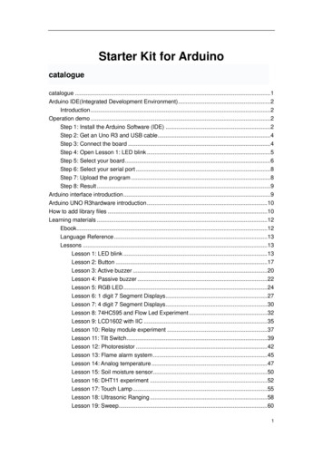
TitleProject 4 – Flame SensorExpected outcome:You will interface a flame sensor to the Arduino.This sensor is specially designed to isolatespecific bands in the IR and UV wavelengths andlooks for unique patterns in flames for anextremely accurate reading.What you need: Arduino Prototype BoardBreadboard and Jumper Wires1x Flame Sensor (Pictured Right)1x 220 Ohm Resistor. (Brn, Blk, Blk, Red, Red)The Circuit:Note: If you get no reading when igniting a flame near the sensor, try reversing it. It is a polar device and needs to be in the correctway. It will not be damaged in this circuit if it is placed backwards.Date12
TitleThe Code://----Begin Code (copy from here)---//Variablesint inPin A0; //Pin the sensor is connected toint sensorVal 0; //Variable to store sensor datavoid setup() {// put your setup code here, to run once:Serial.begin(9600);Serial.println("Serial Communication started.\nReady to detect Flame.");}void loop() {// put your main code here, to run repeatedly:sensorVal analogRead(inPin); //analogRead will read the voltage on the pin specified andreturn it as a value between 0 and 1024.if (sensorVal 1000) {//FlameSerial.print("Flame: ");Serial.println(sensorVal);}else {//Uncomment the lines below to view the raw sensor data.//You can change the "if statement" above to reflect the difference in sensitivity and ambientvalues//Serial.print("Sensor Value: ");//Serial.println(sensorVal);}}//----End Code (copy to here)----Try it out:Upload and run the code. You should see the Serial monitor display:Serial Communication started.Ready to detect Flame.If you now light a lighter within the detection radius of the sensor, you will see the serialmonitor output:Flame: xxxWhere xxx is the sensor reading.Now that we can detect a flame, we can move along to the next project! Capturing and usingdata from an IR remote control!Date13
TitleProject 5 – RemoteExpected outcome:You will build a circuit to demodulate and report thecodes of individual buttons of various IR remotes aroundthe house, as well as the one in the kit. If you wish tobuild a project based off this circuit you should google“Arduino switch” and select the link with the title “switchcase”. This will show you the method for executingdifferent actions depending on the remote codereceived.What you need: Arduino Prototype BoardBreadboard and Jumper Wires1x IR Receiver and Remote (Receiver pictured right)IRremote library from:https://www.pjrc.com/teensy/arduino libraries/IRremote.zipNOTE: In this project we are using a library for the first time. The library will download as a ZIP file. You should thenextract the files to your Arduino installation folder/librarieseg: C:\Program Files (x86)\Arduino\librariesIf you have problems with this step google search “Using libraries with Arduino” for easy to follow guides.The Circuit:Note: The sensor should face you, so when you click a button on the remote it can easily pick it up.Date14
TitleThe Code://----Begin Code (copy from here)---#include IRremote.h //Notice we have included the IRremote library here.//Variables:IRrecv irrecv(10); //Set up the IR Reciever, call it irrecv and attach it to the correct pindecode results results; //Set up a variable to hold the resultsvoid setup(){// put your setup code here, to run once:Serial.begin(9600);irrecv.enableIRIn(); // Start the receiverirrecv.blink13(true); //Blinks the LED on the Arduino board as it gets data from the remote.}void loop() {// put your main code here, to run repeatedly:if (irrecv.decode(&results)) {String tmp (String)results.value;if (tmp "4294967295") //This value tells the Arduino that the previous button is still active.{Serial.println("Button still active."); //Report to the serial monitor the last button was still helddown}else {Serial.println(results.value, HEX); //A new button has been pressed with the value shown.}irrecv.resume(); // Receive the next value}}//----End Code (copy to here)----Try it out:Upload the code and open the serial monitor.Aim the included remote at the receiver (the side with the metal X crossing it) and watch theserial output window! What projects would you make using this method of remote control?It wouldn’t take much code to start looking for specific hex codes, and performing tasks basedon which input was observed! Our future project books will cover some fun topics using theremote!Feel free to have a play with various IR transmitters from around your house.When you areready, let’s move on to the next project – Tilt Sensors!Date15
TitleProject 6 – Tilt SensorExpected outcome:You will learn to interface with the simple tilt sensor. Thissensor is essentially a steel bearing in a tube. The leadsgo inside, and when the bearing is at the bottom of thecan it completes the circuit. When the bearing rolls upthe can the circuit is broken.What you need: Arduino Prototype BoardBreadboard and Jumper WiresThe Circuit:Note: This component has no polarity, it can be inserted either way and work the same. The leads are often bent various ways inorder to have it activate and deactivate at the correct angles.Date16
TitleThe Code://----Begin Code (copy from here)---//Variables:void setup() {// put your setup code here, to run once:Serial.begin(9600);Serial.println("Serial Established.\nTilt board to continue.");pinMode (7, INPUT); //Set pin 7 to input for reading the sensor.}void loop() {// put your main code here, to run repeatedly:if (digitalRead(7) true){Serial.println("Tilted!");}else {Serial.println("Upright!");}}//----End Code (copy to here)----Try it out:Notice that if you tilt the board the output changes from upright to tilted. You could use thissensor to start a function that makes your robot stand up for instance.Now that we have added another sensor to the list of components we can use, let’s moveforward to another type of output! The RGB LED module!Date17
TitleProject 7 – RGB LED ControlExpected outcome:You will be able to control the color output of an RGBLED module from your Arduino.What you need: Arduino Prototype BoardBreadboard and Jumper Wires1x RGB Module (Pictured Right)The Circuit:Note: the image is slightly different to the module you got, however it is wired the same. The LED should be towards you. It will bequite bright. I recommend a piece of paper or tissue over the lens.Date18
TitleThe Code://----Begin Code (copy from here)---//Variables:int rPin 11;int gPin 10;int bPin 9; //Set the PWM pins to be used on the arduinoint rVal 0;int gVal 0;int bVal 0; //Set the values to 0 to begin withvoid setup() {// put your setup code here, to run once://No setup for this project.}void loop() {// put your main code here, to run repeatedly:analogWrite(rPin, rVal);analogWrite(bPin, bVal);analogWrite(gPin, gVal); //Apply PWM output to each leg of the RGB LED, with the value storedin the corresponding variable.rVal random(0,255);gVal random(0,255);bVal random(0,255); //Randomise the variables to get a random color each timedelay(500); //Delay before changing colors, so we can see each change.}//----End Code (copy to here)----Try it out:The RGB LED should now cycle through random colors, every half a second the color shouldchange. The LED is quite bright, I found it much easier to look at once I had placed a small pieceof printer paper over the top of it, it also helps mix the colors better.If you wish to experiment with mixing your own colors, delete the following section of code:rVal random(0,255);gVal random(0,255);bVal random(0,255); //Randomise the variables to get a random color each timedelay(500); //Delay before changing colors, so we can see each change.And now you can set the values for each color in the Variables section. When you compile and run youwill see your custom color there!Now that we can use an RGB LED in our projects, let’s move on to reading a potentiometer.Date19
TitleProject 8 – Read a potentiometerExpected outcome:You will be able to take user input and process it. Youmight use this as an input for sensitivity, volume,intensity, or even as an analog input for a game controlleror similar.What you need: Arduino Prototype BoardBreadboard and Jumper Wires1x Potentiometer (Pictured right)1x 220 Ohm Resistor. (Brn, Blk, Blk, Red, Red)The Circuit:Note: Ensure the control stick is towards you so you can spin it easily.Date20
TitleThe Code://----Begin Code (copy from here)---//Variables:int varPin A0;int val 0;void setup() {// put your setup code here, to run once:Serial.begin(9600);Serial.println("Serial connection established.\nAdjust the Potentiometer to see the valuechange!");}void loop() {// put your main code here, to run repeatedly:Serial.print("Potentiometer Value: ");val analogRead(varPin);Serial.println(val);}//----End Code (copy to here)----Try it out:Notice how the number reading in the Serial Monitor changes depending on the position of thepotentiometer. What projects could you make with this?Let’s move on to the next component! A 7-Segment display!Date21
TitleProject 8 – 7 Segment DisplayExpected outcome:You will wire up and display all theHEXADECIMAL characters on the 7-Segment.Notice there is no possible way to reliably makeall the characters using this display, howeverthey are great for numbers. You can alsosomewhat fashion a workable alphabet if youuse a combination of upper and lowercaseletters, and they don’t have to be exactly right.What you need: Arduino Prototype BoardBreadboard and Jumper Wires1x 7-Segment Display moduleThe Circuit:Date22
TitleThe Code://----Begin Code (copy from here)---//Variables:int pin a 6;int pin b 7;int pin c 8;int pin d 9;int pin e 10;int pin f 11;int pin g 12;int pin h 13;int delayVar 500;void setup() {// put your setup code here, to run once:pinMode(pin a, OUTPUT);pinMode(pin b, OUTPUT);pinMode(pin c, OUTPUT);pinMode(pin d, OUTPUT);pinMode(pin e, OUTPUT);pinMode(pin f, OUTPUT);pinMode(pin g, OUTPUT);pinMode(pin h, OUTPUT);}void loop() {// put your main code here, to run repeatedly:ch 0();delay(delayVar);ch 1();delay(delayVar);ch 2();delay(delayVar);ch 3();delay(delayVar);ch 4();delay(delayVar);ch 5();delay(delayVar);ch 6();delay(delayVar);ch 7();delay(delayVar);ch 8();delay(delayVar);ch 9();delay(delayVar);ch a();delay(delayVar);Date23
Titlech b();delay(delayVar);ch c();delay(delayVar);ch d();delay(delayVar);ch e();delay(delayVar);ch f();delay(delayVar);delay(delayVar);}void ch a(){digitalWrite(pin a, LOW);digitalWrite(pin b, HIGH);digitalWrite(pin c, LOW);digitalWrite(pin d, HIGH);digitalWrite(pin e, HIGH);digitalWrite(pin f, HIGH);digitalWrite(pin g, HIGH);digitalWrite(pin h, HIGH);}void ch b(){digitalWrite(pin a, LOW);digitalWrite(pin b, HIGH);digitalWrite(pin c, HIGH);digitalWrite(pin d, HIGH);digitalWrite(pin e, HIGH);digitalWrite(pin f, HIGH);digitalWrite(pin g, HIGH);digitalWrite(pin h, HIGH);}void ch c(){digitalWrite(pin a, LOW);digitalWrite(pin b, LOW);digitalWrite(pin c, HIGH);digitalWrite(pin d, HIGH);digitalWrite(pin e, LOW);digitalWrite(pin f, HIGH);digitalWrite(pin g, HIGH);digitalWrite(pin h, LOW);}void ch d(){digitalWrite(pin a, LOW);digitalWrite(pin b, HIGH);Date24
TitledigitalWrite(pin c, HIGH);digitalWrite(pin d, HIGH);digitalWrite(pin e, HIGH);digitalWrite(pin f, LOW);digitalWrite(pin g, LOW);digitalWrite(pin h, HIGH);}void ch e(){digitalWrite(pin a, LOW);digitalWrite(pin b, LOW);digitalWrite(pin c, HIGH);digitalWrite(pin d, HIGH);digitalWrite(pin e, LOW);digitalWrite(pin f, HIGH);digitalWrite(pin g, HIGH);digitalWrite(pin h, HIGH);}void ch f(){digitalWrite(pin a, LOW);digitalWrite(pin b, LOW);digitalWrite(pin c, LOW);digitalWrite(pin d, HIGH);digitalWrite(pin e, LOW);digitalWrite(pin f, HIGH);digitalWrite(pin g, HIGH);digitalWrite(pin h, HIGH);}void ch 1(){digitalWrite(pin a, LOW);digitalWrite(pin b, HIGH);digitalWrite(pin c, LOW);digitalWrite(pin d, LOW);digitalWrite(pin e, HIGH);digitalWrite(pin f, LOW);digitalWrite(pin g, LOW);digitalWrite(pin h, LOW);}void ch 2(){digitalWrite(pin a, LOW);digitalWrite(pin b, LOW);digitalWrite(pin c, HIGH);digitalWrite(pin d, HIGH);digitalWrite(pin e, HIGH);digitalWrite(pin f, HIGH);digitalWrite(pin g, LOW);Date25
TitledigitalWrite(pin h, HIGH);}void ch 3(){digitalWrite(pin a, LOW);digitalWrite(pin b, HIGH);digitalWrite(pin c, HIGH);digitalWrite(pin d, LOW);digitalWrite(pin e, HIGH);digitalWrite(pin f, HIGH);digitalWrite(pin g, LOW);digitalWrite(pin h, HIGH);}void ch 4(){digitalWrite(pin a, LOW);digitalWrite(pin b, HIGH);digitalWrite(pin c, LOW);digitalWrite(pin d, LOW);digitalWrite(pin e, HIGH);digitalWrite(pin f, LOW);digitalWrite(pin g, HIGH);digitalWrite(pin h, HIGH);}void ch 5(){digitalWrite(pin a, LOW);digitalWrite(pin b, HIGH);digitalWrite(pin c, HIGH);digitalWrite(pin d, LOW);digitalWrite(pin e, LOW);digitalWrite(pin f, HIGH);digitalWrite(pin g, HIGH);digitalWrite(pin h, HIGH);}void ch 6(){digitalWrite(pin a, LOW);digitalWrite(pin b, HIGH);digitalWrite(pin c, HIGH);digitalWrite(pin d, HIGH);digitalWrite(pin e, LOW);digitalWrite(pin f, HIGH);digitalWrite(pin g, HIGH);digitalWrite(pin h, HIGH);}void ch 7(){digitalWrite(pin a, LOW);Date26
TitledigitalWrite(pin b, HIGH);digitalWrite(pin c, LOW);digitalWrite(pin d, LOW);digitalWrite(pin e, HIGH);digitalWrite(pin f, HIGH);digitalWrite(pin g, LOW);digitalWrite(pin h, LOW);}void ch 8(){digitalWrite(pin a, LOW);digitalWrite(pin b, HIGH);digitalWrite(pin c, HIGH);digitalWrite(pin d, HIGH);digitalWrite(pin e, HIGH);digitalWrite(pin f, HIGH);digitalWrite(pin g, HIGH);digitalWrite(pin h, HIGH);}void ch 9(){digitalWrite(pin a, LOW);digitalWrite(pin b, HIGH);digitalWrite(pin c, HIGH);digitalWrite(pin d, LOW);digitalWrite(pin e, HIGH);digitalWrite(pin f, HIGH);digitalWrite(pin g, HIGH);digitalWrite(pin h, HIGH);}void ch 0(){digitalWrite(pin a, LOW);digitalWrite(pin b, HIGH);digitalWrite(pin c, HIGH);digitalWrite(pin d, HIGH);digitalWrite(pin e, HIGH);digitalWrite(pin f, HIGH);digitalWrite(pin g, HIGH);digitalWrite(pin h, LOW);}//----End Code (copy to here)----Try it out:What we have done here is create a function for each character that we will display. In this caseI have included the full HEX range. Perhaps you can merge this and the IR remote project, tohave this display read off the code captured from the remotes.Date27
TitleYou could of course create more functions for the rest of the alphabet. In my next project book Iwill rewrite this code so instead of specifying a function for each character, we will instead call afunction with the string we want to display as a parameter like so:displayString("String");The displayString function will then work out the individual characters in the string and lightthem in order on the display with a configurable delay. It will also support the full stop whichRight now I have not added.To add more characters try setting all the pins to LOW except one (making sure to call thefunction you are modifying in the loop()). This will illuminate one section of the display. Onceyou have done this for each section and written down which pin corresponds to which segmentyou can create any shape possible as I have done :).Let’s move on to the next module, the Passive Buzzer!Date28
TitleProject 10 – Passive BuzzerExpected outcome:You will be able to use a passive buzzer, which isessentially
Thank you to Aus Electronics Direct for supplying me with the kit to make this book, my wife Heidi, my son John and my daughter Cortana! I look forward to doing this again. 12 example projects to get you started with your Arduino. By: Tyson Popynick Exclusively for Aus Electronics Direct