Transcription
ElectronicBrick StarterKitGetting Started Guide v1.0 by
IntroductionHello and thank you for purchasing the Electronic Brick Starter Packfrom Little Bird Electronics. We hope that you will find learningabout electronics and the Arduino micro controller system fun andinteresting.The Arduino system is an open-source electronics prototypingplatform based on flexible, easy to use hardware and software; andis intended for artists, designers, hobbyists, and anyone interestedin creating interactive objects or environments. [1]So that means YOU!The benefits of using the Electronic Brick system are many,including: Rapid prototyping of your ideasNo need for soldering or any fiddly tool workVery strong connections help create a robust prototypeNo tiny parts to worry about losing, which also allows peopleof all ages to enjoy the system and build something You are only limited by your imagination!Although this guide will help you get started with your ElectronicBrick system, it is not a complete tutorial on the Arduino system.You could do very well by using this in conjunction with the book“Getting Started with Arduino” by Massimo Banzi. This is availableonline from Little Bird Electronics at:http://bit.ly/br4aHqSo let's get started!
Getting StartedYou will require a few things to start working with your ElectronicBricks. Let's review what these are:1) A personal computer running either Linux, Windows or Mac OS2) An Arduino Duemilanove or compatible board (below)These are available online from Little Bird Electronics.3) An A-B USB cable to connect your Arduino to your computer4) A pair of side-cutters or tinsnips5) Your imagination!
SoftwareYour Arduino and Electronic Brick require a combination of hardwareand software. The hardware consists of the physical things, theboard, bricks, sensors, wires and so on.The software consists of the code (or “sketch”) that you create tocontrol your Arduino, as well as the IDE (“Integrated DevelopmentEnvironment”) software which is required on your personalcomputer.Think of the IDE as a word-processor that you use to enter yoursketch, check for coding errors, and upload the sketch to yourArduino board.Furthermore, you can also use the IDE software to receive data fromyour Arduino, either as an output of data from your prototype (forexample, current temperature) or to help debug your sketch.Installing the IDE software is very simple, a complete set ofinstructions is available at:http://arduino.cc/en/Guide/HomePageOnce you have installed the IDE as per the instructions, try the“blink” example that follows. Once you have successfully created amesmerising blinking LED, you are ready to move on.
PreparationNow it is time to prepare the contents of your Electronic Brick foruse. We should check the contents and get the bricks ready to workfor us. When you open your package for the first time, you shouldhave the following components: An electronic brick “Chassis” (top left)An LCD module (top right)Nine electronic bricks on one printed circuit boardOne multi-coloured ribbon cableFive three-wire cablesThe next thing to do is separate the electronic bricks into individualinto individual units. This can be done easily with some side cuttersor tinsnips.
Starting from the outside perforations, cut away the joins of theprinted circuit board. This may require some force as the board isquite thick, but if you cut slowly and carefully, this is an easyprocess.Once you have separated the bricks, let's examine them in moredetail. There are two types of input/output parts, digital andanalogue, as well as some other bricks.Digital parts are inputs or outputs that only have two states. Thatis, they are either on or off, high or low, noisy or silent, one orzero, etc.Included in your starter kit are the following digital parts:Two LEDs (light emitting diodes). One is red, the other green. Thecan be used in digital and analogue modes.
One LCD (liquid crystal display). This LCD can display two rows ofsixteen characters, and also has a back light which can be turned onor off with the slide switch above the display. Although this is adigital device, it uses the multi-coloured ribbon cable to connect tothe BUS2 socket on the chassis.One piezo buzzer. This can be used in analogue or digital modes. Itcan create a very loud, piercing buzzing noise, great for alarms orwarnings, or just annoying other people.One push button. Used to receive input from a user.
One tilt switch. The white tube on the left holds a small metal ball,and when the switch is tilted, the ball makes or breaks an electricalconnection. Therefore you could think of this as a switch, that turnson or off depending on the angle at which it is held.Analogue parts are inputs or outputs that can have a varied rangeof input or output result. An example of an analogue control thatyou have seen would be a dimmer switch for a bedroom light, or thevolume control on a radio.Included in your starter kit are the following analogue parts:One rotation module. This is a variable resistor, used to createvariable input data for your prototypes.One light sensor. This is a light-dependant resistor, which returns avalue that is related to the amount of ambient light. Useful formaking a protype that reacts to the change in daylight.
One temperature sensor. This uses a thermistor, whose internalresistance is is proportional to the ambient temperature.Other bricks and parts that you should have include the following:Wires. You will have one ribbon cable, used to connect the LCDscreen to the chassis, and five three-wire cables, used to connectthe input/output bricks to the chassis.One terminal brick. This allows you to connect an external pair orwires into the brick system, to be used as an interface to theoutside world.
One chassis. This sits on top of your Arduino Duemilanove, andallows simple connections to various ports. It allows you to useanalogue connections A1 A5, digital connections D8 D12, the UARTand IIC interface, and also has three “bus connections” BUS1 3.These “bus” connections are used to save time, as they are acombination of various Arduino control and power pins. At this stagethe most commonly used will be BUS2, as this is ideal for connectionwith the LCD screen brick.The chassis also has a reset button at the lower-right of the board,and a power LED at the lower-left.Electropus says: Ready? Let's go!
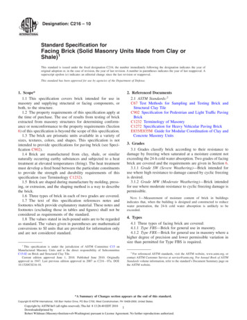
Using your Bricks!Lesson One – Digital input/outputFirst of all, we will explore digital inputs and outputs. These arethe easiest to work with, and quite relevant. First of all, pleasemake the following connections: Place the chassis on top of the Arduino until the pins travel allthe way into the Arduino socket Using three-wire leads, connect an LED to the chassis D12socket, and the push button to the D8 socket.You should have a hardware setup as below:
Next, we need to create our “sketch”, or code to control our inputsand outputs. Enter the following code into the Arduino IDEsoftware:/*Lesson One*/void setup(){pinMode (12, OUTPUT);pinMode (8, INPUT);}// set the socket D12 as an output// set the socket D8 as an inputvoid loop(){if (digitalRead(8) HIGH) // if the button has been// pressed{digitalWrite(12, HIGH); // turn on the LEDdelay(100);}digitalWrite(12,LOW); // turn off the LED}Finally, plug the USB cable into your Arduino board and click the'upload' button on the toolbar. This is below the “Tools” menuoption. Wait a moment, then press your pushbutton.Hooray! We have light.If you like, you can add more outputs that react to the button. Forexample, connect the other LED to digital pin 11, and add anotherdigitalWrite(11, HIGH); // turn on the LEDafter the first digitalWrite command. Also, you will need to tellthe Arduino that digital pin 11 will also be an output, and to turn ifoff when the other LED is off. (See your sketch for a hint!)Upload your sketch, and press the button. Now both LEDs shouldlight.
Lesson Two – Tilt AlarmNow you know how to use a digital input to help make a decision,let's do so in a more interesting way. Replace the push button withthe tilt switch, and have both LEDs in use. Place the green LED intodigital pin 12 and the red on digital pin 11.Our sketch will check the tilt switch, when it it tilted (on, or“high”) it will activate the red LED. When it is level (off, or “low”)the red LED will be off and the green LED on (for “all is well”)./*Lesson Two*/void setup(){pinMode (12, OUTPUT);pinMode (11, OUTPUT);pinMode (8, INPUT);}// set the socket D12 as an output// set the socket D12 as an output// set the socket D8 as an inputvoid loop(){if (digitalRead(8) HIGH) // if the tilt switch// activated{digitalWrite(12, LOW); // turn off the green LEDdigitalWrite(11, HIGH); // turn on the red LEDdelay(200); // give 200 milliseconds delay for LEDs to//activate properly}digitalWrite(12,HIGH); // turn on the green LEDdigitalWrite(11,LOW); // turn off the red LED}So now you have created a silent “burglar alarm”. That's all verygood if you can monitor your output LEDs, but what if you need towander off for a moment or two? Time to make some noise!
Lesson Three – Noisy Tilt AlarmUsing the previous lesson we created a response to the state of a tiltswitch, using a red and green LED. This time we will make use of thepiezo buzzer, to alert us with a noisy screech when the tilt switchgoes “high”. Connect your buzzer brick to digital pin 9. Yourhardware should look something like the layout below:By now you should be realising how easy it is to experiment andprototype your ideas from plans to reality. Although this is startingto look like Electropus, it really is fun and easy to work with.Now for our sketch:/*Lesson Three*/void setup(){pinMode (12, OUTPUT); // set the socket D12 as an outputpinMode (11, OUTPUT); // set the socket D12 as an outputpinMode (9, OUTPUT); // set the socket D9 as an outputpinMode (8, INPUT);// set the socket D8 as an input}void loop(){if (digitalRead(8) HIGH) // if the tilt switch// activated{digitalWrite(12, LOW); // turn off the green LED
digitalWrite(11, HIGH); // turn on the red LEDdigitalWrite(9, HIGH);delay(200); // give 200 milliseconds delay for LEDs to//activate properly}digitalWrite(12,HIGH); // turn on the green LEDdigitalWrite(11,LOW); // turn off the red LEDdigitalWrite(9, LOW); // turn off the buzzer}How did you go? Is that noise as annoying as possible? Great!However, the objects of the lessons so far have been simple, yetpowerful. Now you should understand the concept of digital inputsand outputs, and how they can work for you.Electropus says:I hope you are having fun with your bricks and your imagination isstarting to think of fun things to do! Now on to the next lesson!
Lesson Four – Analogue vs. DigitalNow it is time to have some fun with analogue inputs and outputs. Agood point to start is with our rotation brick, the variable resistor.Depending on the position of the knob the Arduino will return anumerical value between 0 and 1023 (which relates to an inputvoltage of between 0 and 5 volts DC).For our hardware, connect the LEDs to digital pins 11 and 12, andthe rotation brick to analogue pin 1. Your hardware should looksomething like the layout below:And now for our sketch:/*Lesson Four*/void setup(){pinMode (12, OUTPUT);pinMode (11, OUTPUT);}// set the socket D12 as an output// set the socket D12 as an outputint del 0; // this stores the value from the rotational// brick, it will be used as the delay value// for the flashing LEDs
void loop(){del analogRead(1); // put the analog result from the// rotation brick into the variable deldigitalWrite(12,HIGH); // turn on the green LEDdigitalWrite(11,LOW); // turn off the red LEDdelay (del); // wait for the period of time specified by// the rotation brick;digitalWrite(12,LOW); // turn on the green LEDdigitalWrite(11,HIGH); // turn off the red LEDdelay (del); // wait for the period of time specified by// the rotation brick;}Lesson Five – Dark vs. LightNow it is time to experiment with another analogue brick – the lightdependant resistor (LDR). Think of this as a resistor that changes itsvalue in relation to the level of ambient light. Again, simple to use,it can replace the rotational brick from our last sketch.In fact, do that now – replace the rotational brick with the LDR.Notice how the flash rate increases with the darkness. So this meansthe darker the ambient light, the higher the resistance of the LDR.The sketch for this lesson is identical to lesson five, as we are justsubstituting the rotational brick with the LDR brick.Electropus asks:“But what values do these analogue sensors return?”
Lesson Six – Using your PC to read sensor dataNow that we have some experience with analogue sensors and whatthey can do, we now should learn what values they are sending tothe Arduino. If you have a idea of these values, you can calibrateand otherwise do more with the sensors involved.The aim of this lesson is to send the values of the sensors back tothe host personal computer, so we can read these values in realtime. First of all, connect the rotational brick to analogue pin 5, theLDR brick to analogue pin 1, and the push button brick to digital pin8.Now for our sketch. We will use the Serial commands to send thevariable data back to the host computer. This computer needs to berunning the Arduino IDE software at the time./*Lesson Six*/void setup(){Serial.begin(9600);// opens serial port, sets data rate// to 9600 bps}int rotational 0; // this stores the value from the// rotational brickint ldr 0; // this stores the value from the LDR brickvoid loop(){rotational analogRead(5); // store value of rotational// brickldr analogRead(1); // store value of LDR brickdelay (100); // wait for 100 millisecondsSerial.print("Rotational "); // send information to the//serial portSerial.print(rotational);Serial.print(" - LDR ");Serial.println(ldr);delay(500); // wait half a second}
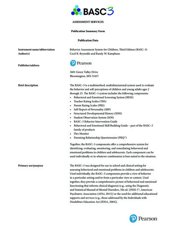
Once you have uploaded the sketch to your Arduino, leave the IDEsoftware open. Now click the “Serial Monitor” button (below the“tools” option on the menu bar). A new window should appear,check the speed is set to 9600 bps (at the bottom right).You should have something like this:By adjusting the rotational brick knob, and altering the lightavailable to the LDR, you will be able to see their values on the PCscreen. These are the values you can compute with your Arduinosketch to respond to such sensors.
Lesson Seven – Hot or not?The final analogue sensor we have in our brick package is thetemperature sensor. It is a thermistor that changes its resistancedepending on the ambient temperature.For our hardware, just connect the temperature brick to analoguepin 5.Now for our sketch. Again, we will use the Serial commands to sendthe variable data back to the host computer. This computer needs tobe running the Arduino IDE software at the time./*Lesson Seven*/void setup(){Serial.begin(9600);// opens serial port, sets data rate//to 9600 bps}float temperature 0; // this stores the value from the// temperature sensor brickvoid loop(){temperature analogRead(5); // store value of temp bricktemperature temperature 252-500; // some maths totemperature temperature / 10; // convert to Celsiusdelay (100); // wait for 100 millisecondsSerial.print("Temperature ");Serial.print(temperature);Serial.println(" degrees Celsius.");delay(500); // wait half a second}Once again, after you have uploaded the sketch to your Arduino,leave the IDE software open. Now click the “Serial Monitor” button(below the “tools” option on the menu bar). A new window shouldappear, check the speed is set to 9600 bps (at the bottom right).
Here is an example of our serial readout from the test PC:The thermistor is not accurate “out of the box” so to speak, so youwill need to have another thermometer with you. Adjust the valueof -500 in the sketch above until your PC readings are as close aspossible to your other thermometer.Electropus says:“great. but I'm not going to carry around my computer to readthe temperature – that's a bit silly!”OK Electropus, we have a solution for that.
Lesson Eight – LCD ScreenFinally we come to make use of that lovely liquid crystal displaythat is included with our starter kit. In the past using such a devicehas been terribly complex, but with the combination of Arduino andthe electronic brick system, it is very easy.First of all, connect the LCD with the coloured ribbon cable betweenthe LCD brick and the BUS2 socket in the middle of our chassis brick;then connect the temperature brick to analogue pin 5.Now for our sketch. As the LCD brick needs functions that were notincluded in the original Arduino command set, the use of a “library”is required. A library is a set of functions that can be imported touse in our sketch. For more information, please visit:http://arduino.cc/en/Reference/LibrariesBut on with the LCD show. Here is our sketch, slightly modifiedlesson seven. Instead of sending the temperature result to the hostcomputer, it will be displayed on the LCD screen:/*Lesson Eight*/#include LiquidCrystal.h // we need this library for the LCD commandsLiquidCrystal lcd(10,11,12,13,14,15,16);/* tells Arduino which pins the LCD is connected to;in this case 10 16, which match the pinouts on chassisBUS2 socket*/void setup(){lcd.begin(16, 2); // tells Arduino the LCD dimensionslcd.setCursor(0,0);lcd.print("Hello electropus!");// print text and move cursor to start of next linelcd.setCursor(0,1);lcd.print("Please wait.");delay(2000);lcd.clear(); // clear LCD screenlcd.setCursor(0,0);
lcd.print("Temperature is ");}float temperature 0; // this stores the value fortemperaturevoid loop(){temperature analogRead(5); // store value from temp bricktemperature temperature 252-500;temperature temperature / 10;// maths to convert reading to temperature in Celsius.// may need calibrating, by comparing with real thermometer// and adjusting value of -500delay (100); // wait for 100 millisecondslcd.print(" Temperature is");lcd.setCursor(0,1);// move cursor to first character of second linelcd.print(temperature);lcd.println(" deg. C.");delay(1000); // wait a second}Now as Electropus was talking about, it is silly to need a computerevery time to run an Arduino sketch. Notice the DC socket on theleft hand side of the Arduino board – this can accept a 9V DC plugpack, with a positive tip, as shown below:
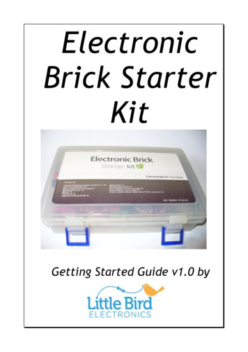
But now for the result of our LCD digital thermometer!So there you have it – you have examined analogue and digitalinputs and outputs, displayed your data on the host PC and also on aliquid crystal display.However this is not the end, only a break between your first andsecond steps on the infinite journey on the fun, exploration,educational and fascinating road of electronics andmicrocontrollers!Electropus says:“I hope you had as much fun as we did. see you again!”
References[1] Arduino home page, http://www.arduino.ccFor more exciting and educational products:Little Bird Electronicshttp://www.littlebirdelectronics.com
Hello and thank you for purchasing the Electronic Brick Starter Pack from Little Bird Electronics. We hope that you will find learning about electronics and the Arduino micro controller system fun and interesting. The Arduino system is an open-source electronics prototyping platform