Transcription
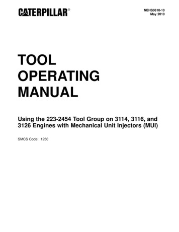
Return to LibraryOperating ManualforVTC-200B, VTC-200C & VTC-300C(Mazatrol Fusion 640M)Publication # C557SG0012E7/99CAUTIONThis Manual is published to assist experienced personnel on the operation, maintenanceand/or programming of Mazak machine tools.All Mazak machine tools are engineered with a number of safety devices to protectpersonnel and equipment from injury or damage. Operators should not, however, relysolely upon these safety devices, but should operate the machine only after fullyunderstanding what special precautions to take by reading the following documentationthoroughly.Do not attempt to operate or perform maintenance / repair on the machine without athorough understanding of the actions about to be taken. If any question exists, contactthe nearest Mazak service center for assistance.Certain covers, doors or safety guards may be open or removed to more clearly showmachine components. These items must be in place before operating the machine.Failure to comply with this instruction may result in serious personal injury or damage tothe machine tool.This manual was considered complete and accurate at the time of publication, however,due to our desire to constantly improve the quality and specification of all Mazakproducts, it is subject to change or modification.
Return to LibraryNotes:
Return to LibraryVTC-200B,200C & 300C Operation.SAFETY PRECAUTIONS .S-1LOCKOUT PROCEDURE .S-4INSTALLATION PRECAUTIONS .S-5WARNINGS .S-8Sec. 1: Introduction .1 INTRODUCTION .1-11-1 List of Related Manuals and Documents .1-11-2 Pagination .1-11-3 Numbering of Figures and Tables .1-22 SAFETY PRECAUTIONS .2-12-1 Rule .2-12-2 Basic Safety Items .2-12-3 Clothing and Personal Safety .2-32-4 Operational Safety .2-32-5 Safety Considerations Relating to Holding Workpieces and Tooling .2-42-6 Maintenance Safety .2-52-7 Workplace Safety .2-62-8 Safety Considerations Relating to Chip Conveyor .2-62-9 Safety Equipment .2-72-10 Remarks on the Cutting Conditions Recommended by the NC .2-82-11 Safety Nameplates .2-8Sec. 2: Machine Operation .1 OUTLINE OF THE MACHINE .1-11-1 Axis Definitions .1-11-2 Names and Locations of Machine Units .1-22 OPERATION PANELS .2-12-1 Locations of Operation Panels .2-12-2 NC Operation Panel .2-2-1 Arrangement of Switches on the NC Operation Panel .2-22-3
Return to Library2-2-2 Names and Functions of Switches and Other Controls on the NC Operation .2-42-3 Auxiliary Operation Panel .2-92-4 Data Input/Output Panel .2-102-5 Magazine Operation Panel .2-112-6 Main Power Disconnect Switch .2-122-7 Operators Door Interlock .2-7-1 MACHINE SET UP Switch (Key-lock Type Switch) .2-132-133 MANUAL OPERATION .3-13-1 Inspection before Starting Operation.3-13-2 Switching the Power ON .3-33-3 Inspection after Switching the Power ON .3-53-4 Switching the Power OFF .3-63-5 Zero-Point Return .3-73-6 Warmup Operation .3-93-7 Spindle Operation .3-7-1 Starting the Spindle .3-7-2 Stopping the Spindle .3-7-3 Jogging the Spindle .3-7-4 Changing the Direction of Spindle Rotation .3-103-103-103-103-113-8 Feed Operation .3-8-1 Rapid Traverse Operation .3-8-2 Cutting Feed Operation .3-8-3 Pulse Handle Feed Operation .3-8-4 Clearing the Soft-Limit Alarm .3-113-113-113-123-133-9 Coolant System Operation .3-153-10 ATC Operation .3-10-1 Manual ATC Operation .3-10-2 Recovering ATC Operation after Interruption .3-163-163-203-11 Chip Conveyor Operation (Optional Specifications) .3-224 PREPARING FOR MACHINING .4-14-1 Procedure for Mounting or Removing a Tool in the Tool Magazine .4-1-1 Procedure for Mounting Tools to the Magazine .4-1-2 Procedure for Removing Tools from the Magazine .4-1-3 Restrictions on Tools .4-14-14-44-54-2 Mounting and Removing Workpieces .4-2-1 Dimensional Restrictions on Workpieces .4-2-2 Procedure for Mounting and Removing Workpieces .4-2-3 Measuring Coordinate Values .4-64-64-74-74-3 Preparing Coolant .4-3-1 Selection of Coolant .4-3-2 Replenishing Coolant .4-84-84-84-4 Adjustment of Coolant Nozzle Direction .4-9
Return to LibrarySec. 3: Operating NC Unit & Preparation for Auto Operation .CONTENTS .4-21 PREPARATION FOR AUTOMATIC OPERATION .1-11-1 Preparation Steps for Automatic Operation .1-12 DISPLAY OVERVIEW .2-12-1 Name of the Components of Each Display .2-12-2 Types of Displays .2-32-3 Configuration of Displays .2-3-1 DISPLAY MAP display .2-42-62-4 Windows .2-73 DATA SETTING METHODS .3-13-1 Setting Data and Address .3-23-2 Selecting Menu Data .3-33-3 Erasing Data .3-33-4 Modifying Data .3-43-5 Incremental Input .3-43-6 Saving Data onto the Hard Disk .3-44 DISPLAYS RELATED TO THE MACHINE OPERATIONAL STATUS .4-14-1 POSITION Display .4-1-1 Data display .4-1-2 Data registration .4-1-3 Display operations .4-14-14-54-64-2 TRACE Display .4-2-1 Data display .4-1-2 Displaying machining shape and tool tip .4-1-3 Plane select .4-1-4 Change of scale values .4-64-74-84-94-94-3 EIA MONITOR Display .4-1-1 Data display .4-1-2 EIA/ISO monitor function .4-1-3 Editing functions .4-1-4 Restart 2 unmodal function .4-114-114-124-124-134-4 MACHINING - MONITORING Display .4-4-1 Data display .4-1-2 Display modes of the MACHINING - MONITORING display .4-1-3 Selecting graphs to be displayed in the machining-monitoring mode .4-1-4 Setting the threshold in the drill-monitoring mode .
Operating Manual for VTC-200B, VTC-200C & VTC-300C (Mazatrol Fusion 640M) Publication # C557SG0012E 7/99 CAUTION This Manual is published to assist experienced personnel on the operation, maintenance and/or programming of Mazak machine tools. All Mazak machine tools are engineered with a number of safety devices to protect personnel and equipment from injury or
