Transcription
Model 72-7770: OPERATING MANUALTable of Contents (1)TitleOverviewUnpacking InspectionSafety InformationRules For Safe OperationInternational Electrical SymbolsThe Meter StructureFunctional ButtonsMeasurement OperationA. DC Voltage MeasurementB. AC Voltage MeasurementC. DC Current MeasurementD. Measuring ResistanceE. Diodes and ContinuityMeasurement1Page3457101112131315172022
Model 72-7770: OPERATING MANUALTable of Contents (2)TitleF. Square Wave OutputGeneral SpecificationsAccuracy SpecificationsA. DC VoltageB. AC CurrentC. DC CurrentD. ResistanceE. Diodes and ContinuityMeasurementF. Square Wave OutputMaintenanceA. General ServiceB. Replacing the BatteryC. Replacing the Fuses2Page25262828293031323233333435
Model 72-7770: OPERATING MANUALOverviewThis Operating Manual covers information on safety and cautions. Please readthe relevant information carefully and observe all the Warnings and Notes strictly.WarningTo avoid electric shock or personal injury, read the “Safety Information” and“Rules for Safety Operation” carefully before using the Meter.The Model 72-7770 Multimeter (hereafter referred as “the Meter”) is 3 1/2digits with steady operations, fashionable design and highly reliable hand-heldmeasuring instrument. The Meter measures AC/DC voltage, AC/DC Current,Resistance, Temperature, Diode and Continuity. It is an ideal tool formaintenance.3
Model packing InspectionOpen the package case and take out the Meter. Check the following items carefullyto see any missing or damaged part:Qty1 piece1 pair1 pieceItemDescriptionEnglish Operating Manual12Test Lead3HolsterIn the event you find items missing or damaged, please contact your dealerimmediately.4
Model 72-7770: OPERATING MANUALSafety Information(1)Safety InformationThis Meter complies with the standards IEC61010: in pollution degree 2, overvoltagecategory (CAT I 600V, CAT II 300V) and double insulation.CAT. I: Signal level, special equipment or parts of equipment, telecommunication,electronic, etc., with smaller transient overvoltages than overvoltages CAT. II.CAT. II: Local level, appliance, PORTABLE EQUIPMENT etc., with smaller transientovervoltages than CAT. IIIUse the Meter only as specified in this operating manual, otherwise the protectionprovided by the Meter may be impaired.5
Model 72-7770: OPERATING MANUALSafety Information(2)In this manual, a Warning identifies conditions and actions that pose hazards to theuser, or may damage the Meter or the equipment under test.A Note identifies theinformation that user should pay attention on.International electrical symbols used on the Meter and in this Operating Manual areexplained on page 10.6
Model 72-7770: OPERATING MANUALRules For Safe Operation (1)WarningTo avoid possible electric shock or personal injury, and to avoid possibledamage to the Meter or to the equipment under test, adhere to the followingrules:l Before using the Meter inspect the case. Do not use the Meter if it isdamaged or the case (or part of the case) is removed. Look for cracks ormissing plastic. Pay attention to the insulation around the connectors.l Inspect the test leads for damaged insulation or exposed metal. Checkthe test leads for continuity. Replace damaged test leads with identicalmodel number or electrical specifications before using the Meter.l Do not apply more than the rated voltage, as marked on the Meter, betweenthe terminals or between any terminal and ground.l The rotary switch should be placed in the correct position and nochange of range shall be made during measurement , to prevent7
Model 72-7770: OPERATING MANUALRules For Safe Operation (2)damage of the Meter.l When the Meter working at an effective voltage over 60V DC or 42V rmsAC, special care should be taken for there is danger of electric shock.l Use the proper terminals, function, and range for your measurements.l Do not use or store the Meter in an environment of high temperature, humidity,explosive, flammable and strong magnetic field. The performance of the Metermay deteriorate after dampened.l When using the test leads, keep your fingers behind the finger guards.l Disconnect circuit power and discharge all high-voltage capacitors beforetesting resistance, continuity, diodes and current.l Before measuring current, check the Meter’s fuses and turn off power tothe circuit before connecting the Meter to the circuit.l Replace the battery as soon as the battery indicator appears. With a lowbattery, the Meter might produce false readings that can lead to electricshock and personal injury.8
Model 72-7770: OPERATING MANUALRules For Safe Operation (3)lllllllRemove test leads and temperature probe from the Meter and turn theMeter power off before opening the Meter case.When servicing the Meter, use only the same model number or identicalelectrical specifications replacement parts.The internal circuit of the Meter shall not be altered at will to avoid damageof the Meter and any accident.Soft cloth and mild detergent should be used to clean the surface of theMeter when servicing. No abrasive and solvent should be used to preventthe surface of the Meter from corrosion, damage and accident.The Meter is suitable for indoor use.Turn the Meter off when it is not in use and take out the battery when notusing for a long time.Periodically check the battery as it may leak after some time.If leakage isapparent,the battery should be immediately replaced to prevent damage.9
Model 72-7770: OPERATING MANUALInternational Electrical SymbolsAC or DCAC CurrentDC CurrentEarth GroundDouble Insulated.Low Battery.Diode.Fuse.Continuity TestSafety RulesConforms to Standards of European Union.10
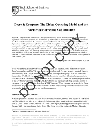
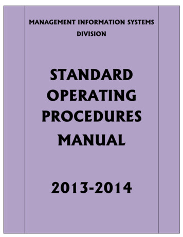
Model 72-7770: OPERATING MANUALThe Meter StructureThe Meter Structure (figure 1)1)2)3)4)5)6)7)LCD DisplayHOLD ButtonDisplay Backlight ButtonRotary SwitchCOM Input Terminal10A Input TerminalOther Input Terminals(figure 1)11
Model 72-7770: OPERATING MANUALFunctional ButtonsThe table below provides information about functional button operation.ButtonOperation Performedl Press HOLD once to enter hold mode.HOLD button l Press HOLD again to exit hold mode.l In Hold mode, H is displayed and the present value is shown.l Press BLUE button once to turn the display backlight on.BLUE button l Press BLUE button again to turn the display backlight off.l Display backlight does NOT be automatically turu off.12
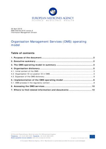
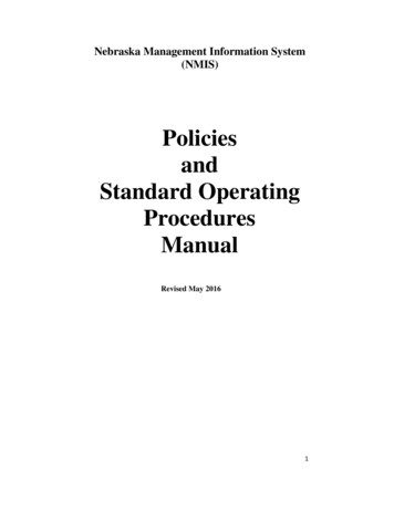
Model 72-7770: OPERATING MANUALMeasurement Operation(1)A. DC Voltage Measurement (see figure 2)WarningTo avoid harm to you or damage to the Meter from electric shock, please donot attempt to measure voltages higher than 500V although readings may beobtained.The DC Voltage ranges are: 200mV, 2000mV, 20V,200V and 500V. To measure DC voltage, connectthe Meter as follows:1.Insert the red test lead into theVΩmAterminaland the black test lead into the COM terminal.2. Set the rotary switch to an appropriatemeasurement position in V range.3. Connect the test leads across with the objectbeing measured.(figure 2)The measured value shows on the display.13
Model 72-7770: OPERATING MANUALMeasurement Operation (2)Notel If the value of voltage to be measured is unknown, use the maximum measurementlllposition (500V) and reduce the range step by step until a satisfactory readingis obtained.The LCD displays “1” indicating the existing selected range is overload; it isrequired to select a higher range in order to obtain a correct reading.In each range, the Meter has an input impedance of approx. 10MΩ. This loadingeffect can cause measurement errors in high impedance circuits. If the circuitimpedance is less than or equal to 10kΩ, the error is negligible (0.1% or less).When DC voltage measurement has been completed, disconnect the connectionbetween the test leads and the circuit under test.14
Model 72-7770: OPERATING MANUALMeasurement Operation (3)B.AC Voltage Measurement (see figure 2)WarningTo avoid harm to you or damage to the Meter from electric shock, please donot attempt to measure voltages higher than 500Vrms although readings maybe obtained.The AC voltage measurement positions are: 200V and 500V. To measure AC Voltage,connect the Meter as follows:1. Insert the red test lead into the VΩmA terminal and the black test lead into theCOM terminal.2. Set the rotary switch to an appropriate measurement position in V range.3. Connect the test leads across with the object being measured.The measured value shows on the display, which is effective value of sine wave(mean value response).15
Model 72-7770: OPERATING MANUALMeasurement Operation (4)Notel If the value of voltage to be measured is unknown, use the maximum measurementlllposition (500V) and reduce the range step by step until a satisfactory readingis obtained.The LCD displays “1” indicating the existing selected range is overload, it isrequired to select a higher range in order to obtain a correct reading.In each range, the Meter has an input impedance of approx. 10MΩ. This loadingeffect can cause measurement errors in high impedance circuits. If the circuitimpedance is less than or equal to 10kΩ, the error is negligible (0.1% or less).When AC voltage measurement has been completed, disconnect the connectionbetween the test leads and the circuit under test.16
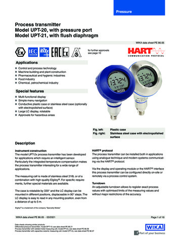
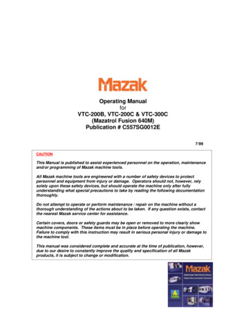
Model 72-7770: OPERATING MANUALMeasurement Operation (5)C. DC Current Measurement (see figure 3)WarningNever attempt an in-circuit currentmeasurement where the voltage betweenterminals and ground is greater than 60V.If the fuse burns out during measurement,the Meter may be damaged or the operatorhimself may be hurt. Use proper terminals,function, and range for the measurement.When the test leads are connected tothe current terminals, do not parallel themacross any circuit.( figure 3)17
Model 72-7770: OPERATING MANUALMeasurement Operation (6)Current measurement has 4 positions on the rotary switch:2000µA, 20mA, 200mA and 10ATo measure current, do the following:1. Turn off power to the circuit. Discharge all high-voltage capacitors.2. Insert the red test lead into the VΩmA or 10A terminal and the black test leadinto the COM terminal.3. Set the rotary switch to an appropriate measurement position in A range.4. Break the current path to be tested. Connect the red test lead to the morepositive side of the break and the black test lead to the more negative sideof the break.5. Turn on power to the circuit.The measured value shows on the display.18
Model 72-7770: OPERATING MANUALMeasurement Operation (7)Notel If the value of current to be measured is unknown, use the maximum measurementposition (10A)l Reduce the range step by step until a satisfactory reading is obtained.l When current measurement has been completed, disconnect the connectionbetween the testing leads and the circuit under test.19
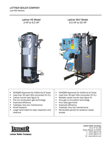
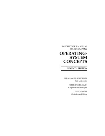
Model asurement Operation (8)D. Measuring Resistance (see figure 4)WarningTo avoid damage to the Meter or to thedevices under test, disconnect circuitpower and discharge all the high-voltagecapacitors before measuring resistance.Resistance measurement positions are:200Ω, 2000Ω, 20kΩ, 200kΩ,20MΩand 200MΩTo measure resistance, connect the Meter asfollows:( figure 4)20
Model 72-7770: OPERATING MANUALMeasurement Operation (9)1.Insert the red test lead into the VΩmA terminal and the black test lead into theCOM terminal.2. Set the rotary switch to an appropriate measurement position in Ω range.3. Connect the test leads across with the object being measured.The measured value shows on the display.Notel The test leads can add 0.1Ωto 0.3Ωof error to resistance measurement. To obtainprecision readings in low-resistance measurement, that is the range of 200Ω,short-circuit the input terminals beforehand and record the reading obtained(called this reading as X). (X) Is the additional resistance from the test lead.Then use the equation:measured resistance value (Y) (X) precision readings of resistance.l For high-resistance measurement ( 1MΩ), it normally takes several secondsto obtain a stable reading.l When resistance measurement has been completed, disconnect the connection21
Model 72-7770: OPERATING MANUALMeasurement Operation (10)between the test leads and the circuit under test.E. Diodes and Continuity Measurement (see figure 5)Testing DiodesWarningTo avoid damage to the Meter or to thedevices under test, disconnect circuitpower and discharge all the high-voltagecapacitors before diodes.Use the diode test to check diodes,transistors, and other semiconductordevices. The diode test sends a currentthrough the semiconductor junction, andthen measures the voltage drop22( figure 5)
Model 72-7770: OPERATING MANUALMeasurement Operation (11)across the junction. A good silicon junctiondrops between 0.5V and 0.8V.To test a diode out of a circuit, connect the Meter as follows:1.Insert the red test lead into the VΩmA terminal and the black test lead into theCOM terminal.2. Set the rotary switch to3. For forward voltage drop readings on any semiconductor component, place thered test lead on the component’s anode and place the black test lead on thecomponent’s cathode.The measured value shows on the display.Notel In a circuit, a good diode should still produce a forward voltage drop reading of0.5V to 0.8V; however, the reverse voltage drop reading can vary depending onthe resistance of other pathways between the probe tips.23
Model 72-7770: OPERATING MANUALMeasurement Operation (12)l Connect the test leads to the proper terminals as said above to avoid error display.lThe LCD will display “1” indicating open-circuit for wrong connection. The unitof diode is Volt (V), displaying the positive-connection voltage-drop value.When diode testing has been completed, disconnect the connection betweenthe test leads and the circuit under test.Testing for ContinuityTo test for continuity, connect the Meter as below:1. Insert the red test lead into the VΩmA terminal and the black
The Model 72-7770 Multimeter (hereafter referred as “the Meter”) is 3 1/2 digits with steady operations, fashionable design and highly reliable hand-held measuring instrument. The Meter measures AC/DC voltage, AC/DC Current, Resistance, Temperature, Diode and Continuity. It is an ideal tool for maintenance. 3 Model 72-7770: OPERATING MANUAL. Open the package case and take out the