Transcription
Original InstructionsCertified Quality1: PUMP SPECSSERVICE & OPERATING MANUALOPTIMIZED PERFORMANCEModel S303: EXP VIEW2: INSTAL & OPMetallicDesign Level 16: OPTIONAL5: WET END4: AIR ENDISO 9001 CertifiedISO 14001 CertifiedWarren Rupp, Inc.7: WARRANTYA Unit of IDEX Corporation800 N. Main St.,Mansfield, Ohio 44902 USATelephone 419.524.8388Fax 419.522.7867SANDPIPERPUMP.COM Copyright 2017 Warren Rupp, Inc.All rights reserveds a n d p i p e r p u m p. c o m
Safety InformationIMPORTANTWARNINGWhen used for toxic or aggressive fluids, the pump shouldalways be flushed clean prior to disassembly.Read the safety warnings and instructions in this manualbefore pump installation and start-up. Failure to comply withthe recommendations stated in this manual could damage thepump and void factory warranty.Before maintenance or repair, shut off the compressed air line,bleed the pressure, and disconnect the air line from the pump.Be certain that approved eye protection and protective clothingare worn at all times. Failure to follow these recommendationsmay result in serious injury or death.When the pump is used for materials that tend to settle outor solidify, the pump should be flushed after each use toprevent damage. In freezing temperatures the pump should becompletely drained between uses.Airborne particles and loud noise hazards. Wear eye and earprotection.CAUTIONIn the event of diaphragm rupture, pumped material may enterthe air end of the pump, and be discharged into the atmosphere.If pumping a product that is hazardous or toxic, the air exhaustmust be piped to an appropriate area for safe containment.Before pump operation, inspect all fasteners for looseningcaused by gasket creep. Retighten loose fasteners to preventleakage. Follow recommended torques stated in this manual.Take action to prevent static sparking. Fire or explosion canresult, especially when handling flammable liquids. The pump,piping, valves, containers and other miscellaneous equipmentmust be properly grounded.Nonmetallic pumps and plastic components are not UVstabilized. Ultraviolet radiation can damage these parts andnegatively affect material properties. Do not expose to UV lightfor extended periods of time.This pump is pressurized internally with air pressureduring operation. Make certain that all fasteners and pipingconnections are in good condition and are reinstalled properlyduring reassembly.WARNINGPump not designed, tested or certified to be powered bycompressed natural gas. Powering the pump with naturalgas will void the warranty.WARNINGThe use of non-OEM replacement parts will void (or negate)agency certifications, including CE, ATEX, CSA, 3A and EC1935compliance (Food Contact Materials). Warren Rupp, Inc. cannotensure nor warrant non-OEM parts to meet the stringentrequirements of the certifying agencies.Use safe practices when liftingkgATEX Pumps - Conditions For Safe Use1.Ambient temperature range is as specified in tables 1 to 3 on the next page (per Annex I of DEKRA 18ATEX0094X)2.ATEX compliant pumps are suitable for use in explosive atmospheres when the equipment is properly grounded inaccordance with local electrical codes3.Non-Metallic ATEX Pumps only — See Explanation of Pump Nomenclature / ATEX Details PageConductive Polypropylene, conductive Acetal or conductive PVDF pumps are not to be installed in applications where thepumps may be subjected to oil, greases and hydraulic liquids.4.The optionally provided solenoids shall be protected by a fuse corresponding to its rated current (max 3*Irat accordingto EN 60127) or by a motor protecting switch with short circuit and thermal instantaneous tripping (set to the ratedcurrent) as short circuit protection. For solenoids with a very low rated current, a fuse with the lowest current valueaccording to the indicated standard will be sufficient. The fuse may be accommodated in the associated supply unitor shall be separately arranged. The rated voltage of the fuse shall be equal or greater than the stated rated voltage of thesolenoid. The breaking capacity of the fuse shall be as high as or higher than the maximum expected short circuit currentat the location of the installation (usually 1500 A). The maximum permissible ripple is 20% for all dc solenoids.*Not applicable for all pump models — See Explanation of Pump Nomenclature / ATEX Details Page5.When operating pumps equipped with non-conductive diaphragms that exceed the maximum permissible projected area,as defined in EN ISO 80079-36 : 2016 section 6.7.5 table 8, the following protection methods must be applied- Equipment is always used to transfer electrically conductive fluids or- Explosive environment is prevented from entering the internal portions of the pump, i.e. dry running.6.Pumps provided with the pulse output kit and used in the potentially explosive atmosphere caused by the presence ofthe combustible dust shall be installed in such a way that the pulse output kit is protected against impact*Not applicable for all pump models — See Explanation of Pump Nomenclature / ATEX Details PageModel S30 Metallicsandpiperpump . coms30mdl1sm-rev1218
Temperature TablesTable 1. Category 1 & Category 2 ATEX Rated PumpsAmbient TemperatureRange [ C]-20 C to 60 C1Process TemperatureRange [ C]1TemperatureClassMaximum Surface Temperature [ C]-20 C to 80 CT5T100 C-20 C to 108 CT4T135 C-20 C to 160 CT3-20 C to 177 C(225 C) T2T200 CPer CSA standards ANSI LC6-2018 US & Canadian Technical Letter R14, G-Series Natural Gas Models are restricted to (-20 C to 80 C) process temperatureTable 2. Category 2 ATEX Rated Pumps Equipped with Pulse Output Kit or Integral Solenoid:2Ambient TemperatureRange [ C]Process TemperatureRange [ C]TemperatureClassMaximum Surface Temperature[ C]-20 C to 60 C-20 C to 100 CT5T100-20 C to 50 C-20 C to 100 CT5T100OptionsPulse OutputKitIntegral SolenoidXXATEX Pulse output or Intergral Solenoid Not Available For All Pump Models See Explanation of Pump Nomenclature / ATEX Details PageTable 3. Category M1 ATEX Rated Pumps for MiningAmbient TemperatureRange [ C]Process TemperatureRange [ C]-20 C to 60 C-20 C to 150 CNote: The ambient temperature range and the process temperature range should not exceed the operatingtemperature range of the applied non-metallic parts as listed in the manuals of the pumps.sandpiperpump . coms30mdl1sm-rev1218Model S30 Metallic 3
SECTION 1: PUMP SPECIFICATIONS.1 Explanation of Nomenclature Performance Materials Dimensional DrawingsSECTION 3: EXPLODED VIEW.8 Composite Repair Parts Drawing Composite Repair Parts List Material CodesSECTION 4: AIR END.11 Air Distribution Valve Assembly Air Valve with Stroke Indicator Assembly Pilot Valve Assembly Intermediate AssemblySECTION 5: WET END.17 Diaphragm Drawings Diaphragm ServicingSECTION 6: OPTIONAL CONFIGURATIONS.19 Solenoid Shifted Air ValveSECTION 7: WARRANTY & CERTIFICATES.20 Warranty CE Declaration of Conformity - Machinery ATEX Declaration of Conformity7: WARRANTY6: OPTIONAL5: WET END3: EXP VIEWSECTION 2: INSTALLATION & OPERATION.5 Principle of Pump Operation Recommended Installation Guide Troubleshooting Guide4: AIR END2: INSTAL & OP1: PUMP SPECSTable of Contents4 Model S30 Metallicsandpiperpump . coms30mdl1sm-rev1218
Your Model #:(fill in from velSXXXXModel #:Check Valve TypeSBallYDesign LevelDesign LevelZWetted MaterialAISHXAluminumCast IronStainless SteelAlloy CUnpainted ionsXXXXXX1 Santoprene/Santoprene2 PTFE-Santoprene/PTFES05 MB Nitrile/NitrileC FKM/PTFEATEX DetailsE EPDM/EPDMII1GExhIICT5.225 C (T2) GaIEPDM/SantopreneII 1D Ex h IIIC T100 C.T200 C DaGI M1PTFE-Neoprene/PTFEEx h I MaMII 2 Santoprene/PTFEG Ex h IIC T5.225 C (T2) GbII2DEx h IIIC T100 C.T200 C DbN Neoprene/NeopreneII 2 G Ex h ia IIC T5 GbII 2 D Ex hValveia IIIC T100 CDbCheckSeatADNB6CA, H, SA, C, YA, H, SA, C, YYour Serial #:A, I, Y, ZStandard6Metal Muffler00Kit Options00. None00P0. 10.30VDC Pulse Output KitP1.Intrinsically-Safe5.30VDC,**0, 6P1110/120VAC 220/240 VACKit**0, 6A1,PulseA2, A3, OutputA4P2. 110/120 or 220/240VACPulse Output ST1Kit 1/2E0. Solenoid Kit with 24VDC CoilATEX DetailsE1. Solenoid Kit with 24VDCPumpKitExplosion-ProofCoil II 1 G Ex h IIC T5.225 C (T2) GaII 1D Ex h IIIC T100 C.T200 C DaOptionsOptionsE2. Solenoid Kit with 24VAC/12VDCI M1 Ex h I Ma CoilE3. Solenoid Kit with 12VDCII 2 G Ex h IIC T5.225 C (T2) Gb600Explosion-Proof Coil II 2 D Ex h IIIC T100 C.T200 C DbE4. Solenoid Kit with 110VAC Coil**0, 6600A, I, Y, Z6A1, A2, A3, A4ATEX DetailS15,S20,S30 MII 1 G Ex h IIC T5.225 C (T2) GaII 1D Ex h IIIC T100 C.T200 C DaI M1 Ex h I MaII 2 G Ex h IIC T5.225 C (T2) GbII 2 D Ex h IIIC T100 C.T200 C DbII 2 G Ex h ia IIC T5 GbII 2 D Ex h ia IIIC T100 C DbII 2 G Ex h mb IIC T5 GbII 2 D Ex h mb tb IIIC T100 C DbATEX 1II 2 G Ex h IIC T5.225 C (T2) GbII 2 D Ex h IIIC T100 C.T200 C DbII 2 G Ex h ia IIC T5 GbII 2 D Ex h ia IIIC T100 C DbSB1, SA1A, I, Y, Z6P1A, H, I, S, XA1. Solenoid Kit with 12 VDCATEX Compliant CoilA2. Solenoid Kit with 24 VDCATEX Compliant CoilA3. Solenoid Kit with 110/120 VAC50/60 Hz ATEX Compliant CoilA4. Solenoid Kit with 220/240 VAC50/60 Hz ATEX Compliant CoilHDF3A150# Raised Face 3" ANSI Flange(Integral Manifold)80 DIN Flange (Integral Manifold)NPT ThreadsBSP (Tapered) ThreadsPB1/4Non-WettedPump PumpKit OptionsMaterialNoneOptions0OptionsOptionsH, SII 2 G Ex h IIC T5.225 C (T2) GbA, H, I, S, XII 2 D Ex h IIIC T100 C.T200 C DbII 2 G E x h ia IIC T5 GbA, H, I, S, XII 2 D Ex h ia(fillIIICinT100 CDbfrom pumpnameplate)ATEX DetailsE5. Solenoid Kit with 110VACExplosion-Proof CoilE6. Solenoid Kit with 220VAC CoilE7. Solenoid Kit with 220VACExplosion-Proof CoilE8. Solenoid Kit with 110VAC, 50 HzExplosion-Proof CoilE9. Solenoid Kit with 230VAC, 50 HzExplosion-Proof CoilSP. Stroke Indicator PinsPump StyleSWettedMaterialOptionsG Ex h mb IIC T5 GbAII 2 AluminumA, H, SA, C, YII 2 D Ex h mb tb IIIC T100 C DbB Nitrile**Pump option 0 is only ATEX compliant with non-wetted material option CC Carbon SteelE M1FEPDMS1F M,Remove wetted material option XN NeopreneWettedNon-WettedS tionsT PTFEII 1 G Ex h IIC T5.225 C (T2) GaV II 1DFKMEx h IIIC T100 C.T200 C DaH, I, SI, ZWI M1UHMWEx h I MaPolyethyleneII 2 G Ex h mb IIC T5 GbII 2 D Ex h mb tb IIIC T100 C DbKit Options (continued)Painted AluminumCast IronPainted Aluminum w/PTFECoated HardwareStainless Steel withStainless Steel HardwarePainted Aluminum withStainless Steel HardwareCast Iron withStainless Steel HardwarePorting OptionsDiaphragm/Check Valve MaterialsConstructionOptionsIEC EEX m T4N/Amodels equipped with thesePumpexplosion-proof solenoid kit options E1, E3,A, CI, II, HI, HC,SI, E7,SS E8 orP1E9, are certified and approvedE5,by the above agencies. They are NOT ATEXcompliant.ATEX DetailsII 1 G Ex h IIC T5.225 C (T2) GaII 1D Ex h IIIC T100 C.T200 C DaI M1 Ex h I MaII 2 G Ex h IIC T5.225 C (T2) GbII 2 D Ex h IIIC T100 C.T200 C DbII 2 G Ex h ia IIC T5 GbII 2 D Ex h ia IIIC T100 C DbATEX DetailII 1 G Ex h IIC T5.225 II 1D Ex h IIIC T100 C.I M1 Ex h I MaII 2 G Ex h IIC T5.225 II 2 D Ex h IIIC T100 C.II, SI, HINote:ConstructionOptionsSI, HI00A, SI, SS, HC, HI00A, HC, HI, SI, SSP1G15, G20, G30H, I, SI, S, Z600A, H, I, S, XA, I, S, Y, Z600ATEX DetailsA, H, I, S, XA, I, S, Y, Z6P1A, H, I, S, XA, I, S, Y, Z6A1, A2, A3, A4II 1 G Ex h IIC T5.225 C (T2) GaII 1D Ex h IIIC T100 C.T200 C DaI M1 Ex h I MaII 2 G Ex h IIC T5.225 C (T2) GbII 2 D Ex h IIIC T100 C.T200 C , T, 7, 8, 9All OptionsAll OptionsHDF1, HDF2S15,S20 NMATEX DetailsI 1 G Ex h IIC T5.225 C (T2) GaII 1D Ex h IIIC T100 C.T200 C DaI M1 Ex h I MaII 2 G Ex h IIC T5.225 C (T2) GbII 2 D Ex h IIIC T100 C.T200 C DbII 2 G Ex h ia IIC T5 GbII 2 D Ex h ia IIIC T100 C nsOptionsKitOptionsCC600CC0, 600sandpiperpump . comII 2 G Ex h mb IIC T5 GbII 2 D Ex h mb tb IIIC T100 C DbCC0 ,6P1CC0 ,6A1, A2, A3, A4s30mdl1sm-rev1218S05, S1F NMWetted Diaphragm/ Check Valve Non-WettedMaterial Check ValveSeatMaterialAIJ30 3"1Non-Wetted Material OptionsSANDPIPER Pump SizeBXPump BrandS1: PUMP SPECSExplanation of Pump NomenclatureATEX DetailsII 1 G Ex h IIC T5.225 C (T2) GaII 1D Ex h IIIC T100 C.T200 C DaI M1 Ex h I MaII 2 G Ex h IIC T5.225 C (T2) GbII 2 D Ex h IIIC T100 C.T200 C DbII 2 G Ex h ia IIC T5 GbII 2 D Ex h ia IIIC T100 C DbConstructionOptionsII, SI00A, I, SI, SS00A, I, II, SI, SSP1Model S30 Metallic 5HDF3MATEX DetailsConstructionOptionsII 1 G Ex h IIC T5.225 C (T2) GaII 1D Ex h IIIC T100 C.T200 C DaI M1 Ex h I MaII00
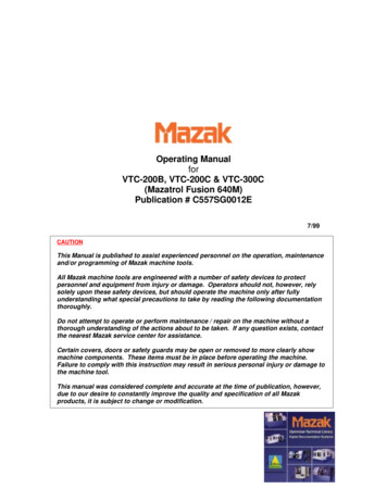
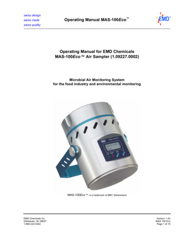
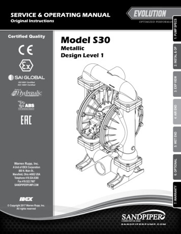
PerformanceBARSUCTION/DISCHARGE PORT SIZE 3" NPT or 3" BSP Tapered 3" ANSI Flange or 3" DIN FlangeCAPACITY 0 to 285 gallons per minute(0 to 1,078 liters per minute)1409AIR DISTRIBUTION VALVE No-lube, no-stall designSOLIDS-HANDLING Up to .38 in. (9.65mm)DISPLACEMENT/STROKE 1.00 Gallon / 3.79 literMAXIMUM OPERATING PRESSURE 125 psi (8.6 bar)SHIPPING WEIGHT Aluminum 116 lbs. (53kg) Cast Iron 215 lbs. (98kg) Stainless Steel 194 lbs. (87kg)20 (34)(34)40 (68)125812071001006HEADHEADS UP TO 125 psi or 289 ft. of water(8.6 Kg/cm2 or 86 meters)MODEL S30 Metallic Performance CurvePerformance based on the following: elastomer fitted pump, flooded suction, water at ambient conditions.The use of other materials and varying hydraulic conditions may result in deviations in excess of 5%.PSI1: PUMP SPECSS30 METALLIC3PSI100 (170)(6.8806060 PS)120 (204).44 Bar)I (4.08140 (238)Bar)40 PSI (2.72 Bar)4020 PSI (1.36200BarSI (521I (8 60 (102).6 Bar)80 (136)80 P54PS00Bar)20100Air 00700
Pump not designed, tested or certified to be powered by compressed natural gas. Powering the pump with natural gas will void the warranty. Use safe practices when lifting kg ATEX Pumps - Conditions For Safe Use WARNING The use of non-OEM replacement parts will void (or negate) agency certifications, including CE, ATEX, CSA, 3A and EC1935 compliance (Food Contact Materials). Warren Rupp, Inc .