Transcription
.CNI,NOITAMGSONIETIUMRAMESASRAEAGHH T ROLA POWKR, INNTIO ADAOMTO IS R 30U0GS A TU R A 93 omAHA 00 S D, C NC.c28 NAR aasC 64OX w.H 1-67ww 0-3380C.OBKO
ST/TLPROGRAMMINGHAAS AUTOMATION INC.2800 Sturgis RoadOxnard, California 93030Phone: 805-278-1800www.HaasCNC.comThis workbook is for the exclusive use of Haas Automation technicians, distributors, educators, andcustomers. Any reproduction, transmission, or use of this workbook or its contents for profit is prohibited.You may reproduce this workbook without written consent for educational purposes. This traininginformation is provided at no cost to all Haas customers and schools currently training with Haasequipment. Modification of this workbook is restricted without written consent from Haas Automation, Inc.The subject matter in this workbook may change without notice. You can scan the QR code below withyour mobile device, or go to diy.haascnc.com to access the most current version.Copyright 2015, Haas AutomationI
PROGRAMMINGST/TLCUSTOMER SATISFACTION POLICYDear Haas Customer,Your complete satisfaction is of the utmost importance to both Haas Automation, Inc., and the HaasFactory Outlet (HFO) where you purchased your equipment. Normally, your HFO will rapidly resolve anyconcerns you may have about the sales transaction or the operation of your equipment.However, if your concerns are not resolved to your complete satisfaction, and you have discussed yourconcerns with a member of the HFO management, the General Manager, or the HFO's owner directly,please do the following:Contact Haas Automation’s Customer Service Advocate at 805-988-6980. So that we may resolve yourconcerns as quickly as possible, please have the following information available when you call: Your company name, address, and phone numberThe machine model and serial numberThe HFO name, and the name of your latest contact at the HFOThe nature of your concernIf you wish to write Haas Automation, please use this address:Haas Automation, Inc. U.S.A.2800 Sturgis RoadOxnard, CA 93030Att: Customer Satisfaction Managere-mail: customerservice@HaasCNC.comOnce you contact the Haas Automation Customer Service Center, we will make every effort to workdirectly with you and your HFO to quickly resolve your concerns. At Haas Automation, we know thata good Customer-Distributor-Manufacturer relationship will help ensure continued success for allconcerned.International:Haas Automation, EuropeMercuriusstraat 28, B-1930Zevantem, Belgiumemail: customerservice@haascnc.comHaas Automation, AsiaNo. 96 Yi Wei Road 67,Waigaoqiao FTZShanghai 200131 P.R.C.email: customerservice@haascnc.comII
ST/TLPROGRAMMINGCON T EN T SINTRODUCTION .1THE COORDINATE SYSTEM. 2HAAS LATHE MACHINE TRAVELS . 3MACHINE HOME . 4ABSOLUTE AND INCREMENTAL POSITIONING. 5TYPICAL LATHE PART . 7PROGRAMMING WITH CODES .10PROGRAM FORMAT. 11DEFINITIONS WITHIN THE FORMAT.13PROGRAM START UP .14PROGRAM ENDING .15SAFE START UP LINE .16PREPARATORY FUNCTIONS "G" CODES .18MISCELLANEOUS FUNCTIONS "M" CODES .19OFTEN USED PREPARATORY "G" CODES.21OFTEN USED PREPARATORY "M" CODES .23ALPHABETICAL ADDRESS CODES .24PROGRAM STRUCTURE.27MACHINE DEFAULTS .29MACHINE CYCLES FOR THE LATHE.30RAPID POSITION COMMAND (G00) .32LINEAR INTERPOLATION COMMAND (G01).33LINEAR INTERPOLATION EXERCISE .34CHAMFERING AND CORNER ROUNDING WITH G01 .35CHAMFERING AND CORNER ROUNDING WITH G01 EXERCISE .39CIRCULAR INTERPOLATION COMMANDS (G02 G03) .41CIRCULAR INTERPOLATION EXERCISES .44MISCELLANEOUS G CODES (G04).47INCH / METRIC SELECTION (G20, G21) .47REFERENCE POINT RETURN COMMANDS (G28 G51) .48SPINDLE SPEED COMMANDS (G50, G96, G97) .49III
PROGRAMMINGST/TLCON T EN T SWORD COORDINATE SYSTEM COMMANDS (G52 G53 G54-G59 G110-G129) .50FEED COMMANDS (G98 G99) .50MANUALLY PROGRAMMING TNC FOR A RADIUS .51MANUALLY PROGRAMMING TNC FOR AN ANGLE .54TOOL NOSE COMPENSATION (G40, G41, G42).57TOOL TIP DIRECTION DIRECTION CHARTS.69EXAMPLE PROGRAM USING TOOL NOSE COMPENSATION .74MACHINE CYCLES FOR TURNING AND GROOVING .77O.D. AND I.D. STOCK REMOVAL CYCLE (G71) .78TYPE I ROUGHING MACHINING DETAILS (G71) .80FINISHING CYCLE (G70) .82G71/G70 TYPE I ROUGHING & FINISHING AN O.D. WITH TNC EXERCISE .85G71/G70 TYPE I ROUGHING & FINISHING AN I.D. WITH TNC EXAMPLE .87TYPE II ROUGH MACHINING DETAILS (G71).88TYPE II ROUGHING EXAMPLE (G71) .8971/G70 TYPE II ROUGHING & FINISHING AN O.D. WITH TNC EXERCISE .90END FACE STOCK REMOVAL CYCLE (G72) .92TYPE I ROUGHING MACHINING DETAILS (G72) .94G72/G70 TYPE I ROUGHING & FINISHING A FACE WITH TNC EXERCISE .96IRREGULAR PATH STOCK REMOVAL CYCLE (G73) .98G73/G70 TYPE I IRREGULAR STOCK REMOVAL & FINISHING AN O.D.WITH TNC EXERCISE .100END FACE GROOVING CYCLE OR HIGH SPEED PECK DRILLING (G74).102G74 SINGLE PASS PROGRAM EXAMPLE.103G74 MULTIPLE PASS PROGRAM EXAMPLE .104G74 HIGH SPEED PECK DRILLING EXAMPLE .105O.D. / I.D. GROOVING CYCLE (G75) .106G75 SINGLE PASS PROGRAM EXAMPLE.107G75 MULTIPLE PASS PROGRAM EXAMPLE .108MULTIPLE PASS THREAD CUTTING CYCLE (G76) .109G76 MULTIPLE PASS THREAD CUTTING CYCLE EXAMPLE . 111IV
ST/TLPROGRAMMINGCON T EN T STHREAD CHARTS. 112G76 O.D. THREADING EXERCISE . 114DRILLING BORING AND TAPPING CANNED CYCLES . 115CANCEL CANNED CYCLE (G80) . 116DRILL CANNED CYCLE (G81) . 116SPOT DRILL/COUNTERBORE CANNED CYCLE (G82) . 117DEEP HOLE PECK DRILLING CANNED CYCLE (G83) . 118TAPPING CANNED CYCLE (G84) .120REVERSE TAPPING CANNED CYCLE (G184) .121BORE IN BORE OUT CANNED CYCLE (G85) .122BORE IN STOP RAPID OUT CANNED CYCLE (G86) .123BORE IN MANUAL RETRACT CANNED CYCLE (G87) .124BORE IN DWELL MANUAL RETRACT - CANNED CYCLE (G88) .125BORE IN DWELL BORE OUT CANNED CYCLE (G89) .126O.D./I.D. TURNING CYCLE MODAL (G90).127G90 MODAL TURNING CYCLE WITH TNC G90 EXAMPLE .128THREAD CUTTING CYCLE MODAL (G92) .129G92 MODAL THREADING CYCLE G92 EXAMPLE .130END FACE TURNING CYCLE MODAL (G94) .131G94 MODAL END FACE CYCLE WITH TNC G94 EXAMPLE .132MISCELLANEOUS CODES SUMMARY (M CODES) .133M CODE DETAILED DESCRIPTION .135V
ST/TLPROGRAMMINGI N T RODU CT I ONA computerized numerical control (CNC) machine controls the tool with a computer and is programmedwith a machine code system that enables it to operate with repeatability and minimal supervision.The same principles used in operating a manual machine are used in programming a CNC machine.The main difference is that instead of using handles to position the tool to a certain location, thelocation is stored in the memory of the machine control. The control moves the tool to this positioneach time the program is run.To operate and program a CNC machine, a basic understanding of machining practices and mathare necessary. It is also important to be familiar with the machine control and the placement of thekeys, switches, displays, etc., that are pertinent to the operation of the machine.This programming workbook provides basic principles necessary to program the Haas lathe. It isnot intended as an in-depth study of all ranges of the machine use. More training and informationare necessary before attempting to program the machine.1
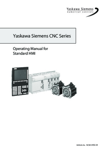
PROGRAMMINGST/TLT H E COORDI N AT E SYST EMThe first diagram that we are concerned with are called NUMBERLINES. This number line has a reference zero point that is calledABSOLUTE ZERO and may be placed at any point along thenumber line.The number line also has numbered increments on either sideof absolute zero. Moving away from zero to the right are positiveincrements. Moving away from zero to the left are negative -”increments. The “ ”, or positive increments, are understood,therefore no sign is needed. The “-” sign is always needed if it’sa negative value. We use positive and negative along with theincrement’s value to indicate its relationship to zero on the line. In the case of the previous line,if we choose to move to the third increment on the minus (-) side of zero, we would call for -3. Ifwe choose the second increment in the plus range,we would call for 2. Our concern is with distance anddirection from zero.Remember that zero may be placed at any point alongthe line, and that once placed, one side of zero hasnegative increments and the other side has positiveincrements.The next illustration shows the two directions of travelon a lathe. To carry the number line idea a little further,imagine such a line placed along each axis of themachine.Haas Lathe X and Z axis linesThe first number line is easy to conceive as belonging to the left-to-right, or “Z”, axis of the machine.If we place a similar number line along the front-to-back, or “X” axis, the increments toward theoperator are the negative increments, and the increments away from the operator are the positiveincrements.The increments on a number line on the Haas lathe equals .0001 inches. While a line theoreticallyhas infinite length in either direction, the two lines placed along the X and Z axes of the machinedo not have unlimited accessibility. That is to say, we are limited by the range of travel on themachine. For the Haas SL-20 for example, we have access to 8.45 inches in the X axis and 20inches in the Z axis.2
ST/TLPROGRAMMINGH AAS LAT H E M ACH I N E T RAV ELSRemember, when we are moving the machine, we are concerned with positioning the turret aroundour workpiece. And our coordinates for positioning the turret are based off a floating zero point orour part origin.Note: The Haas lathe use X dimensions based on the part diameter, not the radius. Thus an Xmove from 0. to 1.0 (X1.0) will only move the tool up .5 on the X axis.The zero position may be placed at any point along each of the two number lines, and in factwill probably be different for each setup of the machine. It is noteworthy to mention here that theX-axis is usually set with the machine zero position on the center line of the spindle, while the Zaxis zero is usually set at the finished right end surface of the part being machined. This placesall X axis cutting in a positive range of travel, whereas the Z axis cutting would be in the negativerange of travel.3
PROGRAMMINGST/TLThe diagram at left shows a front view of the grid as it would appearon the lathe. This view shows the X and Z axes as the operatorfaces the lathe. Note that at the intersection of the two lines, acommon zero point is established. The four areas to the sidesand above and below the lines are called “QUADRANTS” andmake up the basis for what is known as rectangular coordinateprogramming.QUADRANT 1 is on the Top Right at X , Z QUADRANT 2 is on the Top Left at X , ZQUADRANT 3 is on the Bottom Left at X-, ZQUADRANT 4 is on the Bottom Right at X-, Z Whenever we set a zero somewhere on the X axis and somewhereon the Z axis, we have automatically caused an intersection of thetwo lines. This intersection where the two zeros come togetherwill automatically have the four quadrants to its sides, above,and below it. How much of each quadrant that is accessible is determined by where we place thezeros on the travel axes of the lathe.For example, if we set zero exactly in the middle of the Z axis and if we set the X axis zero onthe spindle center line, we have created four quadrants. For an SL-20 for example, the upper twoquadrants of the Z travel is 10 inches and the X travel is 7.45 inches. The lower two quadrants willhave Z travel of 10 inches and X travel of 1 inch. The Haas lathes have 1 inch of negative travelbeyond the center line of the spindle.M ACH I N E H OM EThe principal of machine home may be seen when doing a reference return of all machine axes atmachine startup. A zero return (POWER UP/RESTART) is performed when you power on machine.All axes will then move to the furthest positive locations, to the upper right of machine, until thelimit switches are reached. When this condition is satisfied, the only way to move any of the axesis in the negative direction. This is because the machine zero, is set to the furthest positive point tothe upper right of the machine, when the machine was sent Home with a POWER UP/RESTART.Machine Home is placed at the edge of each axes travel. In effect, now the positive quadrantscannot be reached, and all the X and Z moves will be found to be in the X-, Z- quadrant. It is onlyby setting a new location with, Tool Geometry and Work Zero Offsets somewhere within the travelof each axis that other quadrants are able to be reached.4
ST/TLPROGRAMMINGIt would not be convenient to program our parts from the machine zero, so secondary floating zeropoint is established with offsets. This floating zero is referred to by either, PART ZERO or PARTORIGIN, both having the same meaning.To create the new part zero location, each tool is manually touched off of the part being setup,on the diameter and the length. Then through a series of control key strokes, that distance frommachine zero to the part zero is stored for X & Z axes, in tool offsets, and activated later, from thepart program, when that tool is used for cutting a part.Centerline of the lathe spindle will always be “X” zero and the “Z” zero location will “float” to theface on the part that reflects most of the part length dimensions. Normally the front face is used,because it’s usually easier to access for touch-off procedure and also easier to program.ABSOLU T E AN D I N CREM EN T AL POSI T I ON I N GUp to this point, we have defined a system of positioning the tool that is known as absolute programming.In absolute, all coordinate points are given, in X and Z axis, with regard to their relationship to a fixedpart zero or an origin point. This is the most common type of positioning.Another type of positioning is called incremental. Incremental positioning is defined using U andW. The “U” character is used to specify incremental motion in the X-axis, and the “W” characteris used to specify incremental motion in the Z axis. Both “U” and “W” define distance and direction5
PROGRAMMINGST/TLfrom a point to point location. An incremental coordinate position is entered, using U and W, interms of its relationship to the previous position, and not from a part zero or part origin point. Inother words, after a block of information has been executed, the position that the tool is now at isthe new zero point for the next incremental move to be made. The “U” address is used to specifyan incremental move along the “X” axis and the “W” address is used to specify an incrementalmove along the “Z” axis.An example of the use of the incremental system is shown below. Note that to move from Z-3.375to Z-.625 on the scale, a positive incremental move of W2.750 was made, even though the move Wstill places the tool on the minus side of the Z scale. Therefore the move was determined from thestart point position, with no regard for the fixed zero reference point. The and - signs are usedin terms of direction from the starting point, and are not defined in regard to the part zero point.An example of an incremental move.Keep in mind that when positioning in absolute, we are concerned with distance and directionfrom a fixed part zero reference point, and when positioning in incremental we are concernedwith distance and direction from the last point.Absolute mode should be your positioning mode of choice for most applications. There are timeswhen incremental mode can be quite helpful. Repeating motions within a subroutine, for example,is one excellent example. If you have six identical grooves to turn on a Haas lathe, you can saveprogramming effort if you specify the motions incrementally to machine one groove. Then just callup the subroutine again to repeat the commands to do another groove at a new location.There are even times when it is helpful to command one axis move in the absolute mode whileanother moves in incremental mode. Any turning center using U and W to specify incrementalmotions in X and Z easily allows this. Say you’re experiencing some unwanted taper on a diameterand you want to program a tapering movement to counteract the problem. In the command thatturns the diameter that is experiencing unwanted taper, you can specify the Z endpoint in absolutemode from program zero and the X endpoint as an incremental move. Here is an example:N040 G01 U0.002 Z-2.5 F0.005In this command, the tool will move 0.002 inch, on the diameter, in the X positive direction whilethe Z axis moves to an endpoint of minus 2.5 inches relative to program zero.Note: The Haas lathe uses absolute X dimensions based on the part diameter, not the radius. Thusan X move from 0. to 1.0 (X1.0) will only move the tool up .5 on the X axis.Like X axis absolute moves, incremental U movements are specified for the part diameter, not theradius. Thus a U move from 0. to 1.0 (U1.0) will only move the tool up .5 incrementally on the X axis.6
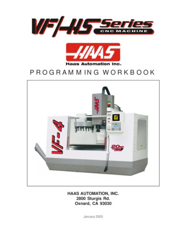
ST/TLPROGRAMMINGT Y PI CAL LAT H E PARTWe can now take this part and show it in a TYPICAL LATHE SETUP, This would include showingthe part, soft jaws, and chuck. Starting with this drawing, you will see this symbolshown on the parts, this target is to indicate where the FLOATING ZERO has beenestablished by the programmer.7
PROGRAMMINGST/TLWe can now take our TYPICAL LATHE PART and record the geometry points needed to programthis part. Diameters are defined as the actual diameter value and not the radius from center.Values for the Points are :X(Diameter not Radius)8ZPoint 1Point 2Point 3Point 4Point 5
ST/TLPROGRAMMINGCalculate and record the X-axis diameters and Z-axis lengths for the part shown below.The values between (parenthesis) would be points where the tool is already located, and thosepoints in a program, would not need to be defined again.XZPt 1Pt 2( )Pt 3Pt 4 ( )Pt 5Pt 6Pt 7 ( )Pt 8( )Pt 9 ( )Pt 10( )Pt 11 ( )Pt 129
PROGRAMMINGST/TLPROGRAM M I N G WI T H CODESThe definition of a part program for any CNC consists of movements of the tool and speed changesto the spindle RPM. It also contains auxiliary command functions such as tool changes, coolanton or off commands, or external M code commands.Tool movements consist of rapid positioning commands, straight line moves or movement alongan arc of the tool at a controlled speed.The Haas lathe has two (2) linear axes defined as X axis and Z axis. The X axis moves the toolturret toward and away from the spindle center line, while the Z axis moves the tool turret alongthe spindle axis. The machine zero position is where the tool is at the upper right corner of thework cell farthest away from the spindle axis. Motion in the X axis will move the turret toward thespindle centerline with negative values and away from spindle center with positive values. Motionin the Z axis will move the tool toward the spindle chuck with negative values and away from thechuck with positive values.A program is written as a set of instructions given in the order they are to be performed. Theinstructions, if given in English, might look like this:LINE #1 LINE #2 LINE #3 LINE #4 LINE #5 LINE #6 LINE #7 SELECT CUTTING TOOL.TURN SPINDLE ON AND SELECT THE RPM.RAPID TO THE STARTING POSITION OF THE PART.TURN COOLANT ON.CHOOSE PROPER FEED RATE AND MAKE THE CUT(S).TURN THE SPINDLE AND COOLANT OFF.RETURN TO CLEARANCE POSITION TO SELECT ANOTHER TOOL.and so on. But our machine control understands only these messages when given in machinecode, also referred to as G and M code programming. Before considering the meaning and theuse of codes, it is helpful to lay down a few guidelines.10
ST/TLPROGRAMMINGPROGRAM FORM ATThere is no positional requirement for the G and M codes. They may be placed in any order withina line of program, which is also known as a block. Each individual can format their programs manydifferent ways. But, program format or program style is an important part of CNC machining. Thereare some program command formats that can be moved around, and some commands need to bea certain way, and there are some standard program rules that are just good to follow. The pointis that a programmer needs to have an organized program format that’s consistent and efficientso that any CNC machinist in your shop can understand it.Some standard program rules to consider are:Program X and Z in alphabetical order on any block. The machine will read Z or X in any order, butwe want to be consistent.When X and Z are both on a command line in a program, they shouldbe listed together and in order. Write X first, and Z second.You can put G and M codes anywhere on a line of code. But, in the beginning when N/C programmingwas being developed G codes had to be in the beginning of a program line and M codes had to beat the end. And this rule, a lot of people still follow and is a good standard to continue.Some CNC machines allow you to write more the one M code per line of code and some won’t.On the Haas, only one M code may be programmed per block and all M codes are activated orcause an action to occur after everything else on the line has been executed.Program format is a series and sequence of commands that a machine may accept and execute.Program format is the order in which the machine code is listed in a program that consist of commandwords. Command words begin with a single letter and then numbers for each word. If it has a plus( ) value, no sign is needed. If it has a minus value, it must be entered with a minus (-) sign. If acommand word is only a number and not a value, then no sign or decimal point is entered withthat command. Program format defines the “language of the machine tool.”.G82 Z-0.2 P0.3 R0.1 F0.003 ;G80 G00 Z1. M09 ;G28 ;MO1 ;;N4 (Drill .312 Dia. x 1.5 Depth) ;G28 ;T404 (5/16 DIA. DRILL) ;G97 S2400 M03 ;G54 G00 X0. Z1. M08 ;G83 Z-1.5 Q0.3 R0.1 F0.006 ;G80 G00 Z1. M09 ;G28 ;MO1 ;.11
PROGRAMMINGST/TLAN EX AM PLE OF T H E PROGRAM ’S FI RST COU PLE OF LI N ES:THE FIRST LINE or block of a program, should be a return to machine zero (using G28 or G51codes). Any tool change should be after a return to machine zero or a tool change location.Although this is not necessary it is a good safety measure.THE SECOND LINE of code should apply to any appropriate tool selections and tool geometryoffsets or tool shifts.THE THIRD LINE may optionally contain a spindle speed maximum for the tool being used.THE FOURTH LINE or block should cancel any constant surface speed mode (G97). And it shouldspecify a constant spindle speed command (S ) along with a spindle ON clockwise command(M03).THE FIFTH LINE should contain a work offset (G54), a preparatory code (G00) forrapid command with an X and Z location for positioning the turret, and turn on thecoolant (M08).THE SIXTH LINE may choose to, optionally specify a Constant Surface Speed with (G96) and asurface feet per minute (SFM) defined with a (S ) command .An example of the program’s startup lines might look like this:With ConstantSurface SpeedN11 G28 ; (All axes move to the machine zero position)N12 T101; (Tool 1, tool offset 01)N13 G50 S2800 ; (Maximum spindle speed set to 2800 rpm)N14 G97 S650 M03 ; (Turns the spindle on (M03) at a constant rpm (G97) of 650 rpm)N15 G54 G00 X1.85 Z1. M08; (Use G54 work offset, rapid move to coordinates, coolanton)N16 G96 S315 ; (Constant surface speed of 315 feet per minute regardless of partdiameter)Without ConstantSurface SpeedN21 G28 ; (All axes move to the machine zero position)N22 T101 ; (Tool 1 , tool offset 01)N23 G97 S1600 M03 ; (Turn spindle on (M03) to constant speed of 1600 rpm)N24 G54 G00 X0. Z1. M08; Use G54 work offset, rapid move to coordinates, coolanton)All the necessary codes for each operation are listed in the following pages. This tool startup formatis a good example and defines a commonly used program style.12
ST/TLPROGRAMMINGDEFI N I T I ON S WI T H I N T H E FORM AT1. CHARACTER : A single alphanumeric character value or the “ ” and “-” sign.2. WORD : A series of characters defining a single function such as, G codes, M codes, and“X” axis moves, or “F” feedrate. A letter is the first character of a word for each of the differentcommands. There may be a distance and direction defined for a word in a program. The distanceand direction in a word is made up of
A computerized numerical control (CNC) machine controls the tool with a computer and is programmed with a machine code system that enables it to operate with repeatability and minimal supervision. The same principles used in operating a manual machine are used in